Language selection

Search

Patent 2817607 Summary

Third-party information liability

Some of the information on this Web page has been provided by external sources. The Government of Canada is not responsible for the accuracy, reliability or currency of the information supplied by external sources. Users wishing to rely upon this information should consult directly with the source of the information. Content provided by external sources is not subject to official languages, privacy and accessibility requirements.

Claims and Abstract availability

Any discrepancies in the text and image of the Claims and Abstract are due to differing posting times. Text of the Claims and Abstract are posted:

  • At the time the application is open to public inspection;
  • At the time of issue of the patent (grant).
(12) Patent: (11) CA 2817607
(54) English Title: DUAL THREAD HAMMERLESS WEDGE AND SPOOL
(54) French Title: COIN ET BRIDE SANS MARTEAU A DOUBLE FIL
Status: Expired and beyond the Period of Reversal
Bibliographic Data
(51) International Patent Classification (IPC):
  • E2F 9/28 (2006.01)
(72) Inventors :
  • KNIGHT, GARRETT D. (Canada)
(73) Owners :
  • RAPTOR MINING PRODUCTS INC.
(71) Applicants :
  • RAPTOR MINING PRODUCTS INC. (Canada)
(74) Agent: METHOD LAW PROFESSIONAL CORPORATION
(74) Associate agent:
(45) Issued: 2016-03-22
(22) Filed Date: 2013-06-04
(41) Open to Public Inspection: 2013-12-06
Examination requested: 2013-11-19
Availability of licence: N/A
Dedicated to the Public: N/A
(25) Language of filing: English

Patent Cooperation Treaty (PCT): No

(30) Application Priority Data:
Application No. Country/Territory Date
61/689,440 (United States of America) 2012-06-06

Abstracts

English Abstract

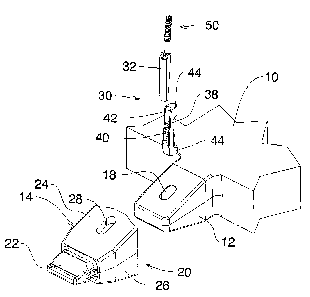
An excavator tooth mounting member attachable to an abutment of an excavator shovel, for supporting an excavator tooth, wherein the abutment has an opening, and having a tooth mounting member with an opening, attachable to the abutment, a two part wedge secured within the openings which can be operated to expand or contract, and a rotary bolt in the wedge.


French Abstract

Un élément de montage de dent dexcavatrice qui peut être fixée à une butée dun godet dexcavatrice, pour supporter une dent dexcavatrice, laquelle butée présente une ouverture, et un élément de montage dune dent avec une ouverture, qui peut être fixée à la butée, un coin à deux parties fixé à lintérieur des ouvertures qui peuvent être actionnées pour se déployer ou se rétracter, et un pêne rotatif dans le coin.

Claims

Note: Claims are shown in the official language in which they were submitted.


The embodiments of the invention in which an exclusive property or privilege
is claimed are
defined as follows;
1. An excavator tooth mounting system attachable to an abutment of an
excavator\
shovel, for supporting an excavator tooth, wherein the abutment has an
abutment
opening, and comprising,
a tooth mounting member with mounting openings, attachable to the abutment;
a two part wedge secured within the mounting openings and the abutment opening
and
able to expand or contract; the wedge having a front wedge portion further
comprising a
front wedge thread of a predetermined first pitch and a rear wedge portion
comprising at
least one rear wedge thread a second predetermined pitch, wherein said first
pitch is finer
than said second pitch the front and rear wedge portions being separable from
one
another,
and a rotary bolt member positioned between said two part wedge portions, to
separate
said wedge portions and, expand said wedge.
2. The excavator tooth mounting system as claimed in claim 1 wherein the
shovel
defines a blade and wherein the openings in the abutments on the shovel are
perpendicular to the blade of the shovel, extending in essentially a vertical
manner, and
wherein the tooth mounting member has mounting openings arranged along an axis
complimentary to the axis of the openings in the abutments.
3. The excavator tooth mounting system as claimed in claim 1, wherein the bolt
has first
pitch bolt threads, complimentary to the first pitch threads on the front
wedge portion and
wherein the bolt has second pitch bolt threads complimentary to the second
pitch threads
on the rear wedge portion.

4. The excavator tooth mounting system as claimed in claim 3 wherein the
front wedge
portion is formed with a front axial semi-cylindrical groove, and the first
pitch threads being
formed in said front groove, and wherein the rear wedge portion is formed with
a rear axial
groove, and wherein the second pitch threads are formed in said rear axial
groove.
5. The excavator tooth mounting member as claimed in claim 4 wherein the rear
wedge
portion has upper and lower arm members defining surfaces engageable with said
mounting member
6. The excavator tooth mounting system as claimed in claim 5 including an eye
on said
front wedge portion to facilitate removal of said wedge.
7. The excavator tooth mounting system as claimed in claim 4 wherein said
front wedge
portion tapers from top to bottom.
8. The excavator tooth mounting system as claimed in claim 4 wherein said
mounting
member defines a recess with an opening of rectangular cross-section, having
top and
bottom walls, and side walls and wherein said mounting openings are formed
through said
top and bottom walls.
9. The excavator tooth mounting system as claimed in Claim 4 wherein said
rear wedge
portion is secured by inter-engagement between said upper and lower arm
members and
said mounting member and said front wedge portion is moveable relative to said
rear
wedge portion.

Description

Note: Descriptions are shown in the official language in which they were submitted.


CA 02817607 2013-06-04
t
FIELD OF THE INVENTION
The invention relates to excavating equipment and in particular to such
equipment
incorporating a shovel or bucket, with replaceable teeth on the leading edge
of the
shovel.
BACKGROUND OF THE INVENTION
Heavy equipment used for earth moving and excavation must withstand abuse and
abrasive working conditions. Such equipment incorporates a shovel or bucket
and the
bucket usually has a plurality of teeth on the leading edge of the bucket.
It is a common experience that such teeth become broken and must be replaced.
In
some cases the teeth are secured simply by a frictional fit, and may become
loose and
lost. In addition, the teeth are subjected to a very high rate of wear, and
must be
replaced at intervals even though they have not been broken or lost. A variety
of
different systems have been proposed for attaching such teeth to the bucket,
which
renders the teeth removable and replaceable. In one particularly useful
system,
abutments are secured permanently to the leading edge of the bucket. Tooth
mounting
members are releasably secured to the abutments, and the actual teeth are
frictionally
secured on the tooth mounting members. This system is useful in that it
permits the
teeth to be replaced, when lost or damaged, and in addition permits the tooth
mounting
members to be removed to facilitate changing the teeth and can be replaced as
needed.
In addition, it is useful because it is possible to retrofit existing
equipment such as
1

CA 02817607 2013-06-04
shovels and excavators, by first of all securing the abutments to the existing
shovel, and
then using those abutments to secure tooth mounting members, and teeth on the
tooth
mounting members.
However, in such systems, some means must be provided for securing the tooth
mounting member to the shovel abutment, in such a way that it is secure for
use but is
none the less rendered capable of being released and removed for replacement.
In the past, these systems have relied on some form of wedge device, and
cooperating
openings and surfaces in the tooth mounting member and the abutment. The wedge
was simply hammered into place. Removing the wedge was tiresome and time
consuming.
BRIEF SUMMARY OF THE INVENTION
For these reasons it is desirable to provide such an attachment system wherein
there is
an abutment on the shovel with an opening, a tooth mounting member also with
an
opening, attachable to the abutment to which an excavator tooth is attachable
and in
which the tooth mounting member is secured on the abutment by means of a two
part
wedge secured within the two openings, and which can be expanded, or
contracted by
operation of a threaded bolt or spool between the two parts.
It is a further objective of the invention to provide such an attachment
system wherein
the opening in the abutment on the shovel is perpendicular to the blade of the
shovel,
extending in essentially a vertical manner, and wherein the tooth mounting
member has
openings arranged along an axis complimentary to the axis of the opening in
the
abutment.
It is a further and related objective of the invention to provide such an
attachment
2

CA 02817607 2013-06-04
system wherein the threaded wedge has a front wedge portion and a rear wedge
portion, separate from one another, and wherein the threaded bolt or spool is
positioned between them, forcing them apart.
It is a further and related objective of the invention to provide such an
attachment
system wherein the front wedge portion is formed with a plurality of first
threads of
relatively fine pitch and wherein the rear wedge portion is formed with a
plurality of rear
wedge threads which are of relatively coarse pitch.
It is a further and related objective of the invention to provide such an
attachment
system and wherein the bolt has both fine threads, complimentary to the fine
threads on
the front wedge portion and wherein the bolt has coarse threads complimentary
to the
coarse threads on the rear wedge portion.
It is a further and related objective of the invention to provide such an
attachment
system wherein the front wedge portion is formed with an axial semi-
cylindrical front
groove, and the fine threads being formed in such groove, and wherein the rear
wedge
portion is formed with an axial rear groove, and wherein such coarse threads
are
formed in said axial rear groove.
It is a further and related objective of the invention to provide such an
attachment
system wherein the rear wedge portion has upper and lower wedging members
defining wedging surfaces, engageable with said abutment on said shovel.
The various features of novelty which characterize the invention are pointed
out with
more particularity in the claims annexed to and forming a part of this
disclosure. For a
better understanding of the invention, its operating advantages and specific
objects
attained by its use, reference should be made to the accompanying drawings and
3

CA 02817607 2013-06-04
descriptive matter in which there are illustrated and described preferred
embodiments
of the invention.
IN THE DRAWINGS
Figure 1 is a perspective illustration exploded, showing a portion of the
shovel and the
tooth support mounting member;
Figure 2 is a section on along line 2-2 of Figure 1; and,
Figure 3 is an enlarged view of the hammerless wedge and spool of the
invention,
exploded.
DESCRIPTION OF A SPECIFIC EMBODIMENT
Referring first of all to Figure 1, a portion only of a typical excavator
bucket is indicated
as (10). It will be appreciated that excavator buckets or shovels of many
different sizes
and shapes may be fitted with the invention.
The excavator bucket is typically fitted with a series of abutments (12) along
the lower
part or blade of the bucket or shovel. The lower part (blade) of the bucket is
usually on
a horizontal transverse plane, as shown.
An excavator tooth mounting member (14) is supported on each abutment (12).
The excavator tooth itself is not shown but would be typically attached on the
leading
end of the mounting member (14). In most cases, such teeth are formed with
recesses
which fit on the leading end of the mounting member and simply make a friction
fit.
The abutment (12) is formed with a through opening (18) for reasons to be
described
along an axis transverse to the blade. The mounting member itself comprises a
steel
4

CA 02817607 2013-06-04
body (20), which is formed with a leading end tip (22) for receiving a tooth
(not shown).
The mounting body (20) is formed a recess opening of rectangular cross-section
with
walls, namely upper and lower clamp walls (24) & side walls (26), which are
shaped to
fit over the abutment (12) on the bucket.
The upper and lower walls(24) of the mounting member are formed with through
openings (28). The through openings (28) extend from top to bottom through
walls (24)
along an axis complimentary to openings (18) and register with the through
opening
(18) in the abutment (12). In order to secure the mounting member firmly on
the
abutment, a wedge indicated generally as (30) is positioned through the
openings (28)
and (18). The purpose of the wedge is to force the walls (24) firmly back onto
the
abutment (12).
The wedge (30) consists of a front wedge bar portion (32), formed with first
threads (34)
which are relatively fine pitch threads. The bar (32) is formed with a
generally semi-
cylindrical recess (36), carrying the threads. The bar (32) tapers from a
smaller lower
end to a wider upper end.
A rear wedge bar portion (38), is formed with coarse threads (40) of a
relatively coarse
pitch, in a generally semi-cylindrical recess (42). Rear wedge portion (38) is
tapered,
being wider at the lower end and narrow at the upper end (Fig 3).
Rear portion (38) has lower and upper clamps (44) extending rearwardly.
The front wedge portion (32) and rear wedge portion (38) further cooperate
with a dual
pitch screw bolt or spool (50). The bolt (50) is formed with two separate sets
of threads
namely a coarse pitch thread (52) and a fine pitch thread (54) and a drive
recess (55).
In operation, the mounting member is placed on the abutment, with the walls
(24) (26)
5

CA 02817607 2013-06-04
=
fitting over the surfaces of the abutment. The rear wedge portion (38) is then
inserted
through the openings (28) and (18). The front wedge portion (32) is then
inserted and
the bolt (50) is engaged with the coarse threads (40), and with the fine
threads.
Clamps (44) engage the edges of upper and lower walls (24). The bolt (50) is
then
rotated and will drive down between the front wedge portion (32) and the rear
wedge
portion (38). As it does so, it will drive the front wedge portion (32) down
into the
openings (28) and (18), and force the two wedge portions apart.
The rear wedge portion (38) is secured by inter-engagement between said upper
and
lower clamps(44) and the mounting member caused by the front wedge portion
moving
relative to the rear wedge portion. This will thus produce a powerful force
urging the
walls (24) (26) of the mounting member back on to the abutment (12).
An eye (56) (Fig 3) is formed at the top end of the front portion (32) to
assist in removal
of the wedge for removal of the tooth mounting members.
The foregoing is a description of a preferred embodiment of the invention
which
is given here by way of example only. The invention is not to be taken as
limited to any
of the specific features as described, but comprehends all such variations
thereof as
come within the scope of the appended claims.
6

Representative Drawing
A single figure which represents the drawing illustrating the invention.
Administrative Status

2024-08-01:As part of the Next Generation Patents (NGP) transition, the Canadian Patents Database (CPD) now contains a more detailed Event History, which replicates the Event Log of our new back-office solution.

Please note that "Inactive:" events refers to events no longer in use in our new back-office solution.

For a clearer understanding of the status of the application/patent presented on this page, the site Disclaimer , as well as the definitions for Patent , Event History , Maintenance Fee  and Payment History  should be consulted.

Event History

Description Date
Time Limit for Reversal Expired 2023-12-06
Letter Sent 2023-06-05
Letter Sent 2022-12-06
Letter Sent 2022-06-06
Common Representative Appointed 2019-10-30
Change of Address or Method of Correspondence Request Received 2019-07-24
Appointment of Agent Requirements Determined Compliant 2019-04-24
Revocation of Agent Requirements Determined Compliant 2019-04-24
Revocation of Agent Request 2019-03-22
Appointment of Agent Request 2019-03-22
Revocation of Agent Request 2019-01-22
Appointment of Agent Request 2019-01-22
Extension of Time to Top-up Small Entity Fees Requirements Determined Not Compliant 2017-06-27
Inactive: Office letter 2017-06-27
Extension of Time to Top-up Small Entity Fees Request Received 2017-06-19
Maintenance Request Received 2016-04-27
Grant by Issuance 2016-03-22
Inactive: Cover page published 2016-03-21
Inactive: Final fee received 2016-01-07
Pre-grant 2016-01-07
Letter Sent 2015-09-17
Notice of Allowance is Issued 2015-09-17
4 2015-09-17
Inactive: Approved for allowance (AFA) 2015-08-17
Inactive: Q2 passed 2015-08-17
Inactive: Adhoc Request Documented 2015-07-29
Amendment Received - Voluntary Amendment 2015-06-19
Maintenance Request Received 2015-05-28
Inactive: S.30(2) Rules - Examiner requisition 2015-03-27
Inactive: Report - QC passed 2015-03-20
Inactive: Cover page published 2013-12-17
Application Published (Open to Public Inspection) 2013-12-06
Letter Sent 2013-12-02
All Requirements for Examination Determined Compliant 2013-11-19
Request for Examination Requirements Determined Compliant 2013-11-19
Request for Examination Received 2013-11-19
Inactive: First IPC assigned 2013-07-15
Inactive: IPC assigned 2013-07-15
Letter Sent 2013-06-18
Inactive: Filing certificate - No RFE (English) 2013-06-17
Application Received - Regular National 2013-06-14
Small Entity Declaration Determined Compliant 2013-06-04

Abandonment History

There is no abandonment history.

Maintenance Fee

The last payment was received on 2015-05-28

Note : If the full payment has not been received on or before the date indicated, a further fee may be required which may be one of the following

  • the reinstatement fee;
  • the late payment fee; or
  • additional fee to reverse deemed expiry.

Patent fees are adjusted on the 1st of January every year. The amounts above are the current amounts if received by December 31 of the current year.
Please refer to the CIPO Patent Fees web page to see all current fee amounts.

Fee History

Fee Type Anniversary Year Due Date Paid Date
Application fee - small 2013-06-04
Registration of a document 2013-06-04
Request for examination - small 2013-11-19
MF (application, 2nd anniv.) - small 02 2015-06-04 2015-05-28
Final fee - small 2016-01-07
MF (patent, 3rd anniv.) - small 2016-06-06 2016-04-27
MF (patent, 4th anniv.) - small 2017-06-05 2017-06-01
MF (patent, 5th anniv.) - small 2018-06-04 2018-05-30
MF (patent, 6th anniv.) - small 2019-06-04 2019-04-03
MF (patent, 7th anniv.) - small 2020-06-04 2020-04-07
MF (patent, 8th anniv.) - small 2021-06-04 2021-05-26
Owners on Record

Note: Records showing the ownership history in alphabetical order.

Current Owners on Record
RAPTOR MINING PRODUCTS INC.
Past Owners on Record
GARRETT D. KNIGHT
Past Owners that do not appear in the "Owners on Record" listing will appear in other documentation within the application.
Documents

To view selected files, please enter reCAPTCHA code :


To view images, click a link in the Document Description column (Temporarily unavailable). To download the documents, select one or more checkboxes in the first column and then click the "Download Selected in PDF format (Zip Archive)" or the "Download Selected as Single PDF" button.

List of published and non-published patent-specific documents on the CPD .

If you have any difficulty accessing content, you can call the Client Service Centre at 1-866-997-1936 or send them an e-mail at CIPO Client Service Centre.


Document
Description 
Date
(yyyy-mm-dd) 
Number of pages   Size of Image (KB) 
Representative drawing 2013-11-07 1 10
Description 2013-06-03 6 224
Claims 2013-06-03 2 74
Abstract 2013-06-03 1 11
Drawings 2013-06-03 3 69
Cover Page 2013-12-16 1 34
Claims 2015-06-18 2 78
Representative drawing 2016-03-08 1 10
Cover Page 2016-03-08 1 35
Courtesy - Certificate of registration (related document(s)) 2013-06-17 1 103
Filing Certificate (English) 2013-06-16 1 156
Acknowledgement of Request for Examination 2013-12-01 1 176
Reminder of maintenance fee due 2015-02-04 1 112
Commissioner's Notice - Application Found Allowable 2015-09-16 1 162
Commissioner's Notice - Maintenance Fee for a Patent Not Paid 2022-07-17 1 541
Courtesy - Patent Term Deemed Expired 2023-01-16 1 537
Commissioner's Notice - Maintenance Fee for a Patent Not Paid 2023-07-16 1 540
Fees 2015-05-27 1 28
Amendment / response to report 2015-06-18 4 148
Final fee 2016-01-06 1 30
Maintenance fee payment 2016-04-26 1 28
Relief mechanism 2017-06-18 1 22
Courtesy - Office Letter 2017-06-26 1 48
Maintenance fee payment 2019-04-02 1 26
Maintenance fee payment 2020-04-06 1 27
Maintenance fee payment 2021-05-25 1 26