Note: Descriptions are shown in the official language in which they were submitted.
CA 02817698 2013-05-31
AUTOMATED HIGH VOLUME SLIDE PROCESSING SYSTEM
Background of the Invention
1. Field
The present invention relates to equipment and methods for preparing samples
for
analysis. In particular, equipment and methods are provided for automated
staining of biological
samples on microscope slides.
2. Background
Many tissues do not retain enough color after processing to make their
components
visible under a bright-field microscope. Accordingly, it is common practice to
add color and
contrast to tissue components by staining the tissue with various reagents. In
the past, the steps
of staining a tissue sample for histological or cytological analysis were
performed manually, a
process that is inherently inconsistent. Inconsistent staining makes it
difficult for a Histologist or
other medical personnel to interpret slides and to make comparisons between
different samples.
Thus, a number of devices and methods have been described that serve to
automate the staining
process and reduce staining inconsistency. Labor costs and the burgeoning
demand for
anatomical pathology services also are driving the push for increased
automation of the staining
process.
Prior art devices for automated staining, especially for high volume staining
with
traditional reagents such as hematoxylin and eosin (H&E), are primarily of a
"dip and dunk"
type, where racks of slides are automatically lowered into and removed from a
series of reagent
baths. For example, U.S. Patent No. 4,911,098 to Tabata describes an automated
staining
1
CA 02817698 2013-05-31
apparatus, where microscope slides holding tissue specimens are dipped
sequentially into a large
number of chemical solution containers. The slides are mounted vertically in a
slide holder
basket and a clamp that engages and disengages the basket is used to move the
slides from
solution to solution. The clamp can include a mechanism to tilt the basket,
which aids in
removing excess solution before the basket is submerged in the next solution.
Additional
automated staining devices of the "dip and dunk" type are described in U.S.
Patent No.
5,573,727 to Keefe, U.S. Patent No. 6,080,363 to Takahasi et al., U.S. Patent
No. 6,436,348 to
Ljungmann et al. and U.S. Patent Application Publication No. 2001/0019703,
naming Thiem et
al. as inventors.
A common shortcoming of the automated "dip and dunk" staining devices is the
possibility for cross-contamination of samples that are simultaneously or
sequentially introduced
into the same solution baths. For example, cells that become dislodged from
one slide can settle
onto other slides introduced into the same bath. Another problem inherent to
these designs is
that as slide baskets are transferred from one bath to another, solutions used
in later steps of the
staining process become contaminated with residual amounts of solutions used
earlier in the
process. Furthermore, degradation (such as through oxidation) of solution
components over time
can lead to inconsistent staining unless the solutions are regularly
replenished or exchanged,
which is a time-consuming and wasteful process that typically disrupts work-
flow in these "dip
and dunk" type of automated stainers.
Another type of automatic staining apparatus delivers fresh reagents directly
to individual
slides. For example, U.S. Patent No. 6,387,326 to Edwards et al. describes an
apparatus for
staining slides where slides are expelled one at a time from a slide storage
device and
individually treated at various staining stations as they move along a
conveyor belt transport
2
CA 02817698 2013-05-31
apparatus. Additional devices for automatically staining individual slides are
described in U.S.
Patent No. 6,180,061 to Bogen et al., PCT Publication WO 03/045560, naming
Tsetmg eta!, as
inventors, and U.S. Patent Application Publication No. US2004/0052685 naming
Richards et al.
as inventors. While such devices can successfully minimize cross-contamination
of slides and
help ensure that samples are consistently treated with fresh reagent, the
individual treatment of
slides lowers throughput. Therefore, the throughput of these individual slide
staining devices
can be problematic for use in primary staining applications (such as H&E
staining) where the
number of samples processed in a histology laboratory can run into the
hundreds or even
thousands per day.
What is needed, therefore, is an apparatus and method for consistent, high-
throughput
staining of microscope slides that also minimizes the potential for cross-
contamination between
slides. Furthermore, an apparatus and method that can be replenished with
fresh reagents
without interruption of work-flow is desirable.
3
CA 02817698 2013-05-31
Summary of the Invention
An automated system is provided for performing slide processing operations on
slides
bearing biological samples. The system enables high sample throughput and
increased staining
consistency while also minimizing the potential for cross-contamination of
slides.
In one aspect of the disclosed system, a workstation for performing a step of
a staining
protocol is not a bath containing a reagent in which several slides are
simultaneously immersed.
Rather, according to this aspect, a workstation of the system dispenses a
reagent to a plurality of
microscope slides with minimal transfer of reagent (and contaminants therein)
between
individual slides. Thus, a workstation according to this aspect minimi7es or
substantially
eliminates the type of cross-contamination of slides that occurs in prior art
"dip and dunk" type
automated slide staining systems, where contaminants such as dislodged cells
can be transferred
through the reagent bath from one slide to another.
In one embodiment, the disclosed system includes a slide tray holding a
plurality of slides
in a substantially horizontal position and a workstation that receives the
slide tray. In a particular
embodiment, a workstation delivers a reagent to slide surfaces without
substantial transfer of
reagent (and reagent borne contaminants such as dislodged cells) from one
slide to another. In
another particular embodiment, the slide tray holding the plurality of slides
holds two or more
rows or banks of slides, for example, two rows of 4-10 slides each.
In a more particular embodiment, slides are held in a rectangular slide tray
in two rows
such that their long dimensions are disposed outward from the central, long
axis of the tray
toward the long edges of the tray. A reagent dispenser in a workstation is
positioned above one
or more pairs of slides in the opposite rows, and delivers a reagent to one or
more slides in one or
4
CA 02817698 2013-05-31
the other of the two rows, for example, to a pair of slides that are opposite
from each other in the
two rows. If the reagent dispenser is positioned above fewer than the total
number of slides that
are held in the tray, the reagent dispenser can move to dispense reagent to
other slides in each
row of slides, and/or the slide tray can be moved to bring additional slides
into position for
reagent dispensing. Alternatively, two or more stationary or moving reagent
dispensers can be
included in the workstation, or one or more manifolds of dispense nozzles can
be positioned
above the two rows of slides, for example, along the central, long axis of the
tray. Nozzles of a
reagent dispenser can direct reagent downward and/or upward toward surfaces of
slides.
In another particular embodiment, a workstation includes two or more sets of
nozzles that
are formed or inserted into a movable block that can be moved along the
central, long axis of the
tray to dispense reagents to one or more slides, for example, a pair of slides
disposed toward
opposite sides of the tray. Since slides are held in the slide tray so that
they are not touching
each other, and the slides are held parallel to one another along the
direction in which a reagent
is dispensed from the nozzles, reagent applied to one slide has a minimal or
substantially non-
existent chance of reaching another slide and thereby cross-contaminating the
slides.
In another aspect, the disclosed system can include one or more workstations
where
biological samples on slides can be subjected to various treatments including
drying, baking, de-
paraffinizing, pre-stain prepping, staining, coverslipping and sealing, and
combinations thereof.
A transporter also is included for moving a slide tray carrying a plurality of
slides between the
plurality of workstations. Additionally, a fluidics module, a pneumatics
module and a control
module can be included to deliver reagents, deliver vacuum and/or pressurized
gas, and
coordinate function of system components, respectively.
5
CA 02817698 2013-05-31
In a particular working embodiment, the disclosed system includes a plurality
of
workstations that are arranged in a vertical stack and a transporter that
comprises an elevator
configured to move a slide tray between the vertically arranged workstations
and an X-Y shuttle
table configured to move a slide tray horizontally, such as in and out of a
workstation, in and out
of the system itself, or in and out of a parking garage. Particular examples
of workstations that
can be included in the system are a baking or drying station, a de-waxing or
de-paraffinizing
station, one or more staining stations and a coverslipping station. In a more
particular
embodiment, a workstation is provided that can perform two or more of de-
paraffmizing,
staining and solvent exchanging. In even more particular embodiments, such a
workstation has a
moveable nozzle assembly configured to deliver reagents to individual slides
held in a slide tray.
Workstations according to the disclosure can be modular and include common
electrical,
pneumatic and fluidic interfaces such that workstation can be easily added or
removed to any of
several positions within a slide processing system.
In another aspect, a fluidics module is disclosed for automated handling of
reagents that
can deliver reagents in packaged concentration or in diluted concentration to
a workstation
without the need to disrupt the delivery of such reagents by the workstation
while replacing or
replenishing reagents to the system. In more particular embodiments, the fluid-
handling module
includes a dual chamber fluid pump. The dual chamber fluid pump includes a
pump chamber
and a dispense chamber where the pump chamber is configured to alternate
between vacuum and
pressure. The two chambers and a set of valves allow the dispense chamber to
be maintained at
a constant pressure for dispensation of a reagent to slides even while
additional reagent is added
to the dispense chamber from the pump chamber. Alternatively, a pump chamber
supplying a
6
CA 02817698 2013-05-31
dispense chamber can further function as a dilution chamber, and a concentrate
pump chamber
can be added to provide concentrated solutions to the dilution chamber.
The disclosed system is capable of high throughput staining of biological
samples on
slides without the shortcomings of conventional dip and dunk systems,
particularly by
eliminating conventional dip-and-dunking de-paraffinizing and/or staining
baths, which tend to
degrade through oxidation and/or contamination by biological cells dislodged
during the de-
paraffinizing process. Instead, the disclosed system can employ fresh, clean
reagents, thus
minimizing the possibility of cell carryover from slide to slide. Moreover,
the disclosed system
provides for the first time a fully integrated high throughput system for
staining slides from the
baking step through the coverslipping step, a process that is not performed by
any other
commercially available system to date.
Further aspects, features and advantages of the disclosed embodiments will be
apparent
from the following detailed description of the invention, which proceeds with
reference to the
following drawings.
Brief Description of the Drawings
FIG. 1 is schematic diagram of an embodiment of the disclosed system.
FIG. 2 is a schematic diagram of a working embodiment of the disclosed system.
FIG. 3 is a perspective view showing a working embodiment of the disclosed
system.
FIG. 4 is a series of schematic drawings showing several different slide tray
arrangements
that can be used in the disclosed system.
FIG. 5 is a perspective view showing an embodiment of a slide tray holding
slides in a
substantially horizontal position.
7
CA 02817698 2013-05-31
FIG. 6 is a perspective view showing another embodiment of a slide tray
holding slides in
a substantially horizontal position.
FIG. 7 is a perspective view showing the bottom of the slide tray of FIG. 6.
FIGS. 8 A-E are a series of perspective views of several embodiments of slide
holding
components of a slide tray.
FIG. 9 is a pair of perspective views showing two different embodiments of a
drying
oven workstation that can be included in the disclosed system.
FIG. 10 is a perspective view showing an embodiment of a de-paraffmizer
workstation
that can be included in the disclosed system.
FIG. 11 is a diagram showing geometric considerations used to determine a heat
profile
for a radiant heater that heats slides in a slide tray substantially
uniformly, and a perspective
view showing a heat profile that can be configured into a radiant heater to
provide substantially
uniform heating of slides in a rectangular slide tray such as the slide tray
of FIG. 6.
FIG. 12 is a perspective view showing an embodiment of a stainer workstation
that can
be included in the disclosed system.
FIG. 13 is perspective view from below showing an embodiment of a combined de-
paraffinizer/stainer workstation that can be included in the disclosed system.
FIG. 14 is an elevational view of an embodiment of a nozzle manifold that can
be used in
the combined de-paraffinizer/stainer workstation of FIG. 13.
FIG. 15 is a schematic diagram showing an embodiment of a fluidics system
supplying
reagents to the nozzle manifold of FIG. 14.
FIG. 16 is a perspective view showing the components of an embodiment of a
solvent
exchanger that can be included in the disclosed system.
8
CA 02817698 2013-05-31
FIG. 17 is a series of diagrams showing an embodiment of a blow-off nozzle
that can also
be used as an air broom.
FIG. 18 is a perspective view showing an embodiment of a coverslipper that can
be
included in the disclosed system.
FIG. 19 is a perspective view showing an embodiment of a coverslipper head.
FIG. 20 a perspective view showing an embodiment of a sealing member of a
coverslipper head.
FIG. 21 is a perspective view showing an embodiment of an X-Y shuttle table
that can be
included in the disclosed system.
FIGS. 22 A-B are a pair of perspective views showing an embodiment of an X-Y-Z
transporter that can be included the disclosed system.
FIG. 23 is perspective view showing an embodiment of a bar code reader
assembly that
can be included in the disclosed system.
FIG. 24 is a flow chart showing a slide tray sequencing scheme.
FIG. 25 is an exploded perspective view showing an embodiment of a dual
chamber
reagent pump.
FIG. 26 is a flow chart illustrating a method of operating the pump of FIG. 25
in a
manner that enables uninterrupted delivery of reagents to system components
even while
reagents are being replenished in the system.
FIG. 27 is an exploded perspective view showing an embodiment of a dual
chamber
dilution and dispensing pump.
FIG. 28 is an exploded perspective view showing an embodiment of a single
chamber
concentrate pump.
9
CA 02817698 2013-05-31
FIG. 29 is a perspective view showing a reagent drawer that can be included in
the
disclosed system.
FIG. 30 is an exploded perspective view of a disclosed reagent supply
container.
FIGS. 31 A-B are perspective views of a collapsible bag of a disclosed reagent
supply
container in its unfilled and filled states.
FIG. 32 is a perspective view of a fitting of a disclosed reagent supply
container.
FIG. 33 is a perspective view of an elastomeric seal of a disclosed reagent
supply
container.
FIGS. 34 A-B are upper and lower perspective views, respectively, of a cover
of a
disclosed reagent supply container.
FIGS. 35 A-B are a perspective and cut-away view of an alternative
septum/fitting
combination for use in a disclosed reagent supply container.
FIG. 36 is perspective view of a disclosed reagent supply container as
assembled.
FIGS. 37 A-B are, respectively, a perspective view showing a piercing tube and
a
perspective view showing a piercing tube inside of a disclosed reagent supply
container.
FIG. 38 is a perspective view showing a disclosed reagent supply container
mounted in a
reagent drawer of the disclosed system.
FIG. 39 is a schematic diagram of an embodiment of a waste emulsification
scheme.
FIG. 40 is a perspective diagram showing an embodiment of an apparatus for,
and a
method of, removing reagents from slides in a slide tray.
FIGS. 41 A-B are diagrams illustrating an alternative apparatus for, and a
method of,
removing reagents from slides in a slide tray.
CA 02817698 2013-05-31
FIG. 42 is a schematic diagram showing electrical and communication
connections of a
working embodiment of the disclosed slide processing apparatus.
Detailed Description of Several Illustrative Embodiments
The following description of several embodiments describes non-limiting
examples of the
disclosed system and methods to illustrate the invention. Furthermore, all
titles of sections
contained herein, including those appearing above, are not to be construed as
limitations on the
invention, rather they are provided to structure the illustrative description
of the invention that is
provided by the specification. Also, in order to facilitate understanding of
the various
embodiments, the following explanations of terms is provided.
I. Terms:
The singular forms "a," "an," and "the" include plural referents unless the
context clearly
indicates otherwise. Thus, for example, reference to "a workstation" refers to
one or more
workstations, such as 2 or more workstations, 3 or more workstations, or 4 or
more workstations.
The term "biological reaction apparatus" refers to any device in which a
reagent is mixed
with or applied to a biological sample, and more particularly to any automated
device that
performs one or more operations on a biological sample.
The term "biological sample" refers to any sample including biomolecules (such
as
proteins, peptides, nucleic acids, lipids, carbohydrates and combinations
thereof) that is obtained
from (or includes) any organism including viruses. Biological samples include
tissue samples
(such as tissue sections), cell samples (for example, cytological smears such
as Pap or blood
smears or samples of cells obtained by microdissection), samples of whole
organisms (such as
11
CA 02817698 2013-05-31
samples of yeast or bacteria), or cell fractions, fragments or organelles
(such as obtained by
lysing cells and separating their components by centrifugation or otherwise).
Other examples of
biological samples include blood, serum, urine, semen, fecal matter,
cerebrospinal fluid,
interstitial fluid, mucous, tears, sweat, pus, biopsied tissue (for example,
obtained by a surgical
biopsy or a needle biopsy), nipple aspirates, milk, vaginal fluid, saliva,
swabs (such as buccal
swabs), or any material containing biomolecules derived therefrom.
The term "code" refers to any type of optical symbology, magnetic pattern or
electromagnetic or electrostatic signal containing information. A "code
reader" is any type of
device that can decipher the information contained in a code. Examples of
optical symbologies
include characters, barcodes and dataglyphs. Particular examples of barcodes
include linear
barcodes (such as EAN.UPC, EAN-128, ITF-14 and code 39) multi-dimensional
barcodes such
as 2D stacked symbologies and 2D matrix symbologies, and composite barcodes
such as reduced
space symbologies. Even more particular examples of 2D optical symbologies
include (,p, q)
code, PDF417, data matrix, maxicode, vericode, codablock, aztec code, code 16K
and QR code.
Bar code readers for these and any number of other optical symbologies are
well known. Where
the code comprises characters (such as alphanumeric characters such as English
text and Arabic
numbers) the code reader can be an optical character reader (OCR). Magnetic
stripes are only
one example of a device that can store information in the form of a magnetic
pattern. An
example of an electromagnetic code is an RFID tag. RFlD tags typically include
a small metallic
antenna and a silicon chip, and can be active or passive. RFlD code readers
are well known, and
typically include an antenna and a transceiver that receives information from
the RFLD tag. The
information content of an RFlD tag can be fixed or changeable. In another
embodiment, the
12
CA 02817698 2013-05-31
code reader comprises a CCD camera and the CCD camera can be used for
simultaneous
detection of slides and reading of a barcode or characters.
The term "organic solvent compatible with coverslipping" refers to a non-
aqueous
solvent (or mixture of such solvents) that can dissolve a glue (such as on a
pre-glued coverslip)
used to affix a coverslip to a slide. Examples of such solvents include
aliphatic and aromatic
hydrocarbons including alkanes (such as branched or straight chain C6-C12
alkanes), terpenes
(such as limonene) and benzene derivatives (such as toluene and xylene).
A "plurality" refers to two or more, for example, 3 or more, 4 or more, 5 or
more, 10 or
more, or even 20 or more.
As used herein, the term "reagent" refers to any liquid or liquid composition
used in a
slide processing operation that involves adding a liquid or liquid composition
to a slide.
Reagents include solutions, emulsions, suspensions and solvents (either pure
or mixtures
thereof). Reagents can be aqueous or non-aqueous. Examples of reagents include
solutions or
suspensions of antibodies, solutions or suspensions of nucleic acid probes,
and solutions or
suspensions of dye or stain molecules (such as H&E staining solutions and Pap
staining
solutions). Further examples of reagents include solvents and/or solutions for
de-paraffinization
of paraffm-embedded biological samples such as limonene, aqueous detergent
solutions, and
hydrocarbons (for example, alkanes, isoalkanes and aromatic compounds such as
xylene).
Additional examples of reagents include solvents (and mixtures thereof) that
can be used to
dehydrate or rehydrate biological samples, such as ethanol, water and mixtures
thereof.
The term "slide" refers to any substrate (such as glass, quartz, plastic or
silicon) of any
dimensions on which a biological sample is placed for analysis, and more
particularly to a
"microscope slide" such as a standard 3" X 1" glass slide or a standard 75 mm
X 25 mm glass
13
CA 02817698 2013-05-31
slide. Examples of biological samples that can be placed on a slide include a
cytological smear,
a thin tissue section (such as from a biopsy), or alternatively, can be an
array of biological
samples, for example a tissue array, a DNA array, an RNA array, a protein
array, or any
combination thereof. Thus, in one embodiment, tissue sections, DNA samples,
RNA samples,
and/or proteins are placed on a slide at particular locations.
The term "slide processing operation" refers to any treatment or manipulation
of a slide,
either with or without a biological sample already placed thereon, or any
treatment of a
biological sample placed on a slide. Examples of slide processing operations
include, but are not
limited to, cleaning, heating, cooling, drying, baking, labeling, indexing,
removing mercury
deposits, re-hydrating, dehydrating, fixing, de-paraffinizing, decalcifying,
bluing, digesting,
preserving, pre-stain prepping, solvent exchanging, mounting, staining and
coverslipping, and
combinations thereof.
The term "staining" is used herein to refer to any treatment of a biological
sample (such
as a cellular smear or a tissue section) that detects and/or differentiates
the presence, location
and/or amount (such as concentration) of a particular molecule (such as a
lipid, protein or nucleic
acid) or particular structure (such as a normal or malignant cell, cytosol,
nucleus, Golgi
apparatus, or cytoskeleton) in the biological sample. For example, staining
can provide contrast
between a particular molecule or a particular cellular structure and
surrounding portions of a
biological sample, and the intensity of the staining can provide a measure of
the amount of a
particular molecule in the sample. Staining can be used to aid in the viewing
of molecules,
cellular structures and organisms not only with bright-field microscopes, but
also with other
viewing tools such as phase contrast microscopes, electron microscopes and
fluorescence
microscopes. Some staining methods can be used to visualize an outline of a
cell. Other staining
14
CA 02817698 2013-05-31
methods rely on certain cell components (such as molecules or structures)
being stained without
staining the rest of a cell. Examples of types of staining methods include
histochernical methods,
immunohistochemical methods and other methods based on reactions between
molecules
(including non-covalent binding interactions), for example, hybridization
reactions between
nucleic acid molecules. Particular staining methods include, but are not
limited to, primary
staining methods such as hematoxylin & eosin (H&E) staining and Pap staining,
enzyme-linked
immunohistochemical methods and in situ RNA and DNA hybridization methods such
as
fluorescence in situ hydbridization (FISH). Additional particular examples of
staining methods
can be found, for example, in Horobin and Kiernan, "Conn's biological stains:
a handbook of
dyes, stains and fluorochromes for use in biology and medicine," 10th ed.,
Oxford: BIOS, ISBN
1859960995, 2002, and in Beesley, "Immunocytochemistry and in situ
hybridization in the
biomedical sciences," Boston: Birkhauser, ISBN 3764340657, 2002.
The term "substantially horizontal" generally refers to an angle within about
+/- 2
degrees of horizontal, for example, within about +/- 1 degree of horizontal
such as within about
+/- 0.8 degrees of horizontal. Substantially horizontal also refers to ranges
of small angles from
horizontal, for example, angles between about 0.1 degrees and 1.8 degrees from
horizontal, such
as angles between about 0.2 degrees and about 1.2 degrees, for example angles
between about
0.3 degrees and about 0.8 degrees. A slide that is held substantially
horizontal will have an
orientation such that the large surfaces of the slide are generally facing up
and down. In
particular embodiments, a rectangular slide such as a microscope slide that is
held substantially
horizontal will have an angle with respect to horizontal of between about 0.0
degrees and about
2.0 degrees along its short axis and an angle with respect to horizontal of
between about 0.0
degrees and 2.0 degrees along its long axis, again with the large surfaces of
the slide generally
CA 02817698 2013-05-31
facing up and down. Typically, if a slide has a barcode affixed to one end, a
slide held in a
substantially horizontal position will have a downward slope away from the
barcode along its
long axis.
The term "wicking member" refers to any structure (made from any material, for
example, metal, plastic or glass) that can break the surface tension of a
liquid held on a surface or
in a container and facilitate liquid movement off of the surface or from the
container. For
example, a wicking member such as a small diameter fiber can come in contact
with the edge of
a slide, and facilitate movement of a liquid from a surface of the slide. A
wicking member such
as a wicking plate can also contact the edge of a slide tray surface (such as
an edge of a bottom
or side wall of a slide tray) to facilitate removal of a liquid accumulated in
the slide tray. A
wicking member is advantageously used in combination with a tilter that lifts
a surface away
from horizontal such that the surface slopes toward the wicking member. The
combination of a
wicking member and a filter can substantially increase the efficiency with
which a liquid can be
removed from the surface or container.
The term "workstation" refers to a position or location in a disclosed system
where at
least one slide processing operation is performed, and more particularly to a
modular unit inside
of which one or more slide processing operations are performed on a plurality
of slides held in a
slide tray (for example, a plurality of slides held in a substantially
horizontal position in a slide
tray). A workstation can receive a slide tray in substantially a single
position so that moveable
components of the workstation can locate individual slides within the slide
tray and precisely
perform a slide processing operation on one or more slides in the tray (such
as deliver a reagent
to a particular slide or portion thereof). Examples of slide processing
operations that can be
performed by a workstation include heating, drying, de-paraffinizing, pre-
stain prepping, rinsing,
16
CA 02817698 2013-05-31
solvent exchanging, staining and coverslipping, and combinations thereof. In
sone
embodiments, a workstation dispenses two or more reagents to a slide without
the slides being
moved from one workstation to another during a slide-processing operation or
operations such as
de-paraffinizing, staining and/or solvent exchanging. Thus, in one embodiment,
a workstation
includes a reagent delivery means such as a nozzle or a manifold of nozzles
through which
reagents are delivered to slides held in a slide tray, which delivery means
can be moveable or
fixed in position within the workstation. Thus, in contrast to some prior art
"workstations"
which are merely containers holding a reagent in which slides are immersed, a
workstation
according to the disclosure can be an active, mechanical device that delivers
reagents (such as
two or more reagents) to groups of slides held together in a slide tray. Thus,
in one aspect a
work station is not a reagent bath in which slide are immersed. In other
embodiments, a
workstation can include a heating element and can further include a heat
directing element. A
heat directing element can help to spread heat more evenly between slides held
in a slide tray. A
workstation also can include one or more radiant heaters. A workstation also
can include a tray
tilter (such as a tilt pan) to lift one end of a slide tray to assist with
liquid removal from the tray.
Alternatively a workstation can include a mechanism to tilt one or more
individual slides in a
slide tray away from a horizontal position. Workstations can further include
various components
that move or control other workstation components, such as stepper motors,
screw drives and
microprocessors. Other components that can be included in a workstation
include hoses, belts,
tracks, fluidics connections, metering pumps, metering valves, electrical
connections, sensors
and the like. In another embodiment, a workstation is a modular unit that can
be interchanged
between two or more positions within a disclosed system and electrically and
fluidically
connected to the system via a common electronics backplane and a common
fluidics manifold.
17
CA 02817698 2013-05-31
In yet another embodiment, a workstation can include a light source, such as a
UV light source
for curing an adhesive for holding a coverslip in place on a slide.
Additionally, sensors located at or near reagent supplies for a workstation
(or at or near
pumps that deliver reagents to a workstation) can monitor reagent volumes in
the system and
alert a user to a low reagent condition. Furthermore, sensors (such as RFID
antennae) can also
be used to track reagent data such as reagent identity, amounts and expiration
dates to help
ensure accurate and consistent reagent use in the system. Overflow conditions
in workstations
and/or in a waste management system can also be monitored with sensors.
II. Overview:
The disclosed staining system can perform all the steps of processing,
staining and
coverslipping of slide mounted biological samples in an efficient high-speed
operation (baking
through coverslipping). In a particular embodiment, slides bearing biological
samples are placed
on a slide tray, and the slide tray bearing the sample slides is loaded into
the system. Then, the
slides in the slide tray are detected and indexed, and conducted through a
sequence of slide
processing operations, for example, baking, de-waxing, staining, coverslipping
and drying.
In one aspect, the disclosed system is an automated slide processing system
that includes
a slide tray holding a plurality of slides in a substantially horizontal
position (such as in two rows
where the slides are held at an angle between about 0.2 degrees and about 1.2
degrees from
horizontal) and one or more workstations (for example, arranged in a vertical
stack) that receive
the slide tray and perform one or more slide processing operations on slides
in the slide tray.
The workstation can perform a slide processing operation on one or more
individual slides in a
slide tray, for example, at least two or four slides in a slide tray, or it
can simultaneously perform
18
CA 02817698 2013-05-31
a slide processing operation on all of the slides in a slide tray. In
particular embodiments, one or
more workstations dispense a reagent to slides in the slide tray without a
substantial amount of
the reagent that contacts a first slide contacting a second slide, thereby
minimizing cross-
contamination between slides. Such workstations can include one or more
directional nozzles
that dispense the reagent onto the slides, for example, the one or more
directional nozzles can
include a pair of directional nozzles that dispense the reagent in opposite
directions across a
surface of a slide. In more particular embodiments, the one or more
directional nozzles can
further include a directional nozzle that dispenses the reagent towards a
bottom surface of a slide.
In other particular embodiments, the one or more workstations can
simultaneously dispense a
reagent (for example, the same reagent) to at least two slides held in a slide
tray within a given
workstation, or the one or more workstations can simultaneously dispense a
reagent (such as the
same reagent) to all of the slides held in the slide tray within a given
workstation.
The disclosed system also can include a transporter to move a slide tray into
and out of
one or more workstations. Another example of a component or workstation that
can be part of
the disclosed system is a radiant heater, for example, a radiant heater that
has a heat profile that
provides substantially uniform heating of slides held in a slide tray
positioned below the radiant
heater. Yet another example of a workstation is a combined de-
paraffinizer/stainer. In a
particular embodiment, a combined de-paraffmizer/stainer includes a moveable
nozzle assembly,
wherein the nozzle assembly includes one or more nozzles through which a
reagent is dispensed
to a slide. The nozzles in the nozzle assembly can be dispense nozzles,
forward top surface rinse
nozzles that can direct a stream of reagent toward a top surface of a slide
(such as at an angle of
between about 20 degrees and about 30 degrees relative to the top surface),
backward top surface
rinse nozzles that can direct a stream of reagent toward a top surface of a
slide (such as at an
19
CA 02817698 2013-05-31
angle of between about 20 degrees and about 50 degrees relative to the top
surface), jet drain
nozzles, and bottom surface rinse nozzles and combinations thereof. One or
more splash guards
can also be included on the nozzle assembly as can one or more air brooms or
blow-off nozzles.
Yet another type of workstations that can be included in the disclosed system
is a
coverslipper. Other examples include a drying oven and a solvent exchanger. A
transporter that
can move a slide tray between workstations also can be included. In more
particular
embodiments, a workstation can include a slide tray filter (such as a tilt
pan) and a wicking
member that facilitates removal of liquids from the slide tray. In
conjunction, a slide tray can
include an opening in a side wall of the slide tray, wherein the opening in
the side wall is
contacted by the wicking member in the workstation.
In a more particular embodiment, a disclosed system includes one or more
workstations
selected from the group consisting of a combined de-paraffmizer/stainer, a
drying oven, a solvent
exchanger, and a coverslipper, a radiant heater, and combinations thereof. The
radiant heater can
have a heat profile that provides substantially uniform heating of the slides
held in the slide tray.
In another aspect an automated slide processing apparatus is provided that
includes a
plurality of workstations including a combined de-paraffinizer/stainer, a
solvent exchanger, and a
coverslipper; a slide tray holding a plurality of slides; and a transporter.
The slides can be held
substantially horizontal in the tray, and the workstations can be arranged in
a vertical stack, such
as a vertical stack where multiple workstations are arranged so they are
essentially above or
below other workstations in the stack. In a particular embodiment, the
combined de-
paraffinizer/stainer and the solvent exchanger dispense a reagent to slides in
the slide tray
without a substantial amount of the reagent that contacts a first slide
contacting a second slide,
thereby minimizing cross-contamination between slides. In more particular
embodiments, the
CA 02817698 2013-05-31
combined de-paraffinizer/stainer and the solvent exchanger each can include a
moveable nozzle
assembly can be positioned to dispense a reagent (such as the same reagent) to
one or more
slides in the plurality (either one at a time in series or simultaneously to
any number-less than the
total number of slides in the tray), or the combined de-paraffinizer/stainer
and the solvent
exchanger each can simultaneously dispense a reagent (such as the same
reagent) to one or more,
(for example, all) of the slides in the plurality through a stationary nozzle
manifold. In this
aspect, the apparatus can further include a radiant heater and/or a drying
oven, wherein the
drying oven can be a convection oven, such as a convection oven including a
heating element
and a blower to distribute heat generated by the heating element across the
slides held in the slide
tray. A dehumidifier can also be included in the system to reduce humidity
within a cabinet
enclosing at least a portion of the system. Furthermore, a sensor such as code
reader for
identifying individual slides on the slide tray can be included in the system
where one or more
slides are marked with a code. Examples of codes that can be used to mark
slides include one-
dimensional barcodes, multidimensional barcodes, glyphs such as dataglyphs,
RFID tags and
magnetic stripes. One or more sensors (such as optical sensors) to detect the
presence of
individual slides (with or without a code) in particular positions within a
slide tray can be
included in the system, and one or more sensors (such as magnet/Hall-effect
sensor
combinations) can be included to detect the presence of a slide tray at
particular positions within
the system. Sensors for detecting individual slides in a slide tray can be
used to ensure that
reagents are not dispensed to positions in a slide tray where no slide has
been placed, thereby
reducing wasteful reagent consumption by the system. In a working embodiment,
an optical
reflectance detector is used to detect slides in the slide tray, and if a
slide is detected, a barcode
reader is used to read a barcode on a slide.
21
CA 02817698 2013-05-31
In a working embodiment of the apparatus, the transporter comprises an X-Y-Z
transport
mechanism, which can be an X-Y shuttle table carried on an elevator. A
counterweight can be
attached to the shuttle table by a cable. Either the counterweight can be
driven by a lead screw
and a stepping motor, or the slide tray can be driven by a lead screw and a
stepping motor. In a
more particular working embodiment, the cable suspends the counterweight
substantially at its
center of gravity and the cable also suspends the shuttle table substantially
at its center of
gravity, thereby reducing moments that could cause binding as they are moved.
A sensor (such
as an optical or magnetic sensor) on the elevator stepping motor (such as a
drive encoder) and or
one or more sensors on the workstations can be used for sensing a location of
the elevator
relative to a workstation in the plurality of workstations. Within one or more
workstations, an
overflow sensor (such as a thermistor) for detecting a fluid overflow
condition can be included.
In a particular embodiment, the solvent exchanger can include a top surface
nozzle that is
directed to a top surface of a slide during at least a portion of a slide
processing operation. It can
also include a bottom surface nozzle directed towards a bottom surface of a
slide during at least a
portion of a slide processing operation. An inline mixer can further be
included in the solvent
exchanger, as well as one or more blow-off nozzles that can be used for
removing and/or
spreading solvents from the slides or over the slides, respectively. A
metering pump can also be
included so that a controlled amount of a reagent fluid is applied to a
surface of a slide.
A working embodiment of the disclosed system also includes a cabinet and a
powered
exhaust for exhausting fumes from the cabinet. A radiant heater also is
included where the
radiant heater provides a substantially uniform heating profile across the
slides held in the slide
tray. A portal formed in a wall of the cabinet for loading and unloading slide
trays also is
22
CA 02817698 2013-05-31
provided in the working embodiment, and further, a de-hpmidifier is added to
decrease humidity
within the cabinet.
Any workstation included in the disclosed system can further include a pan
forming a
bottom wall thereof. The pan can further have a gravity drain formed therein
and/or an overflow
sensor attached thereto such as a thermistor for detecting an overflow
condition in the pan.
In a particular embodiment of a slide tray according to the disclosure,
individual slides
are held in the slide tray spaced from one another in two rows, and, for
example, held
substantially horizontal. As such, a code reader in some embodiments is
positioned to read
codes on slides in one row of the slide tray as the slide tray and/or code
reader are moved in one
direction relative to one another, and the code reader is re-positioned to
read codes on slides on
the other row as the tray and/or bar code reader are moved in an opposite
direction relative to one
another.
Since it is desirable that individual slide positions can be accurately
located by moving
parts within a workstation in order that slide processing operations are
performed precisely a
workstation (such as a combined de-paraffinizer/stainer, a solvent exchanger,
or a coverslipper)
can receive a slide tray in substantially a single position. Therefore, a
workstation can include a
mechanism to hold a slide tray substantially in a single position, for
example, one or more
springs can be used to hold the slide tray substantially in the single
position.
A workstation according to the disclosure (such as a solvent exchanger, a
combined de-
paraffinizer/stainer or a workstation that functions as a solvent exchanger,
de-paraffinizer and
stainer) can include one or more nozzles that dispense a reagent to a top
and/or bottom surface of
a slide held in a slide tray. In some embodiments, the one or more nozzles
include one or more
backward top surface rinse nozzles, one or more bottom surface rinse nozzles,
one or more
23
CA 02817698 2013-05-31
forward top surface rinse nozzles, one or more dispense nozzles, and one or
more jet drain
nozzles. The one or more backward top surface rinse nozzles and the one or
more forward top
surface rinse nozzle can be positioned to deliver a reagent to substantially
the same area on a
slide. The nozzles can be fixed in position within the workstation or can be
moveable within the
workstation such as on a moveable nozzle assembly. In particular embodiments,
the backward
top surface rinse nozzles and the forward top surface rinse nozzles are
positioned to deliver the
reagent at an angle between about 20 degrees and about 50 degrees relative to
a top surface of a
slide and between about 20 degrees and about 35 degrees relative to the top
surface of the slide,
respectively. An air jet or jets that can be used for mixing of reagents
dispensed to a slide
surface (see for example, U.S. Patent No. 5,650,327).
an air broom and/or a blow-off nozzle can be included in a workstation. For
example, a
moveable nozzle assembly can include one or more backward top surface rinse
nozzles, one or
more bottom surface rinse nozzles, one or more forward top surface rinse
nozzles, one or more
dispense nozzles, one or more jet drain nozzles, one or more air jets, one or
more air brooms
and/or one or more blow-off nozzles.
A coverslipper according to the disclosure can include a moveable
coverslipping head,
and the coverslipping head can further include an air broom. The coverslipping
head also can
further include one or more moveable pins that hold a coverslip in position on
a slide while a
hook attached to the head that is holding the coverslip is removed. In one
embodiment, a
coverslipper includes a moveable coverslipping head, wherein the coverslipping
head comprises
a coverslip gripper that includes a flexible backing plate and a sealing
member connected to or
integral with a bottom of the flexible backing plate; the coverslipper further
comprising a
vacuum source communicating with the gripper, and a mechanism for moving the
coverslipping
24
CA 02817698 2013-05-31
head between a source of coverslips and a dispense position where a coverslip
is applied to a
slide. A cassette for holding individual coverslips for pick-up by the gripper
can further be
included, and in particular embodiments, the cassette is keyed to prevent
misloading in the
apparatus. The coverslipper can also include an RFID antennae connected to an
RFED tag reader
(for example, located elsewhere in the system) and an RFD) tag can be included
on the cassette.
Slide processing operations performed by the disclosed system and consumables
tracking
within the system can be controlled by a computer, which can be physically a
part of the system
control module or connected to the system's control module from another
location. In particular
embodiments, the disclosed system can employ two or more distinct layers of
computer/microcomputer electronics hardware (see, for example, FIG. 42).
In some embodiments of the disclosed system, for example, systems having a
single
combined de-paraffinizer/stainer, the system can process up to about 100
slides per hour. In
other embodiments, such as in embodiments having two or three combined de-
paraffinizer/stainers or two or three workstations configured to perform steps
of de-
paraffinization, solvent exchange and staining, the system can process 150 or
200 or more slides
per hours, respectively. In some embodiments two or more drying ovens and two
or more
radiant heaters also are included in the system to increase throughput.
A particular working embodiment of the disclosed automated slide processing
apparatus
includes a slide tray holding a plurality of slides in a substantially
horizontal position; a plurality
of workstations arranged in a vertical stack where the plurality of
workstations includes a
barcode reader, a combined de-paraffinizer/stainer; a solvent exchanger; a
drying oven and a
coverslipper; a transporter, where the transporter includes an X-Y-Z
mechanism, wherein the X-
Y-Z mechanism includes an X-Y shuttle table and an elevator in an elevator
space; a garage
CA 02817698 2013-05-31
adjacent to the elevator space for storing the slide tray; a radiant heater
located above an
uppermost parking station in the garage; a cabinet enclosing the plurality of
workstations, a
dehumidifier for lowering humidity within the cabinet; and a portal through
which the slide tray
is introduced into or taken out of the apparatus. In a more particular working
embodiment, the
combined de-paraffinizer/stainer and the solvent exchanger dispense a reagent
to slides in the
slide tray without a substantial amount of the reagent that contacts a first
slide contacting a
second slide, thereby minimizing cross-contamination between slides.
In another aspect, the disclosure provide a fluidics module that can be
included in the
disclosed slide processing system where the fluidics module is configured to
allow replenishment
of reagent solutions in the system without interruption of workflow in the
system. In one
embodiment, the fluidics module includes one or more dual chamber reagent
pumps, one or more
dual chamber dilution and dispensing pumps, and/or one or more single chamber
concentrate
pumps. Disclosed pump configurations used in disclosed methods of operation
can enable
uninterrupted delivery of reagents to system workstations, even while reagents
are being
replenished in the system.
In another embodiment, two or more consumables used by the apparatus during
operation
are provided in separate packages, wherein the separate packages are keyed
(such as color keyed,
mechanically keyed, optically keyed and/or electronically keyed) to help
prevent misloading of
the packages into the apparatus. In addition, separate packages used in the
system can include a
code (such as an RFID tag) and the apparatus can further include code readers
(such as an RFID
reader and antennae) located adjacent installation locations of the packages.
In a more particular
embodiment, a reagent container is provided for containing a reagent (such as
a biological stain)
for use in a biological reaction apparatus such as the disclosed system. The
disclosed container
26
CA 02817698 2013-05-31
includes a casing having a bottom, sidewalls and a cover, and a collapsible
bag compatible with a
reagent to be contained therein, held within the casing. The collapsible bag
includes a bottom,
sidewalls and a top wall configured and dimensioned to substantially fill the
casing when
expanded (such as when filled with reagent to capacity). The collapsible bag
also has a tube
sealed to the top wall of the bag and extending into an interior of the bag.
The top wall of the
casing is keyed to mate with a corresponding key in the biological reaction
apparatus. In
particular embodiments, the collapsible bag is formed of a flexible polymer
such as a laminated
material, for example, a three layer laminate. In other particular
embodiments, the tube is sealed
to the top wall of the casing and typically one end of the tube extends to or
near the bottom of the
bag. A fitting can be attached to a distal end of the tube, which in
particular embodiment
includes an elastomeric seal. The elastomeric typically includes a thin
material (or septum) that
is easily punctured by insertion of a piercing tube mounted on the apparatus.
The fitting can be
fixedly located under or to the casing lid and the casing cover can include a
cutout for providing
access to the fitting. A removable sealing tape can be placed over the cutout.
In more particular
embodiments, the key can include a color code and/or an interference fit. A
barcode and/or an
RFID tag also can be affixed to an outer wall of the container to, for
example, provide
information about the contents of the container.
Another aspect of the disclosure is a method for automated processing of a
plurality of
biological samples on slides where the slides are held in substantially
horizontal positions in a
slide tray. In one embodiment, the biological samples comprise paraffin-
embedded biological
samples. The method includes moving the slide tray to a first workstation and
automatically
staining the samples in the first workstation and/or automatically de-
paraffmizing the sample
slides in the first workstation and/or automatically solvent exchanging the
samples in the first
27
CA 02817698 2013-05-31
workstation. The method can further include moving the slide tray to a
position under a radiant
heater and melting paraffin in the biological samples prior to moving the
slide tray to the first
workstation. Additionally, the method can include moving the slide tray to a
second workstation
and automatically solvent exchanging the samples through a series of two or
more different
solvents in the second workstation. The method can yet further include moving
the slide tray to
a coverslipper workstation and coverslipping the slides in the slide tray in
the coverslipper
workstation. An alternative embodiment of the method includes moving the slide
tray to the first
workstation, de-paraffinizing the samples in the first workstation, staining
the samples in the first
workstation and also solvent exchanging the samples through a series of two or
more different
solvents in the first workstation. In more particular embodiments, staining
comprises H&E
staining or Pap staining. In an even more particular embodiment, staining
includes dispensing a
hematoxylin solution and an eosin solution to the samples. In another even
more particular
embodiment, staining includes dispensing a hematoxylin solution, an Orange-G
solution and an
Eosin-azure solution to the samples. The method can further include rinsing
the samples (one or
more times with a solution or solvent such as a solution of a surfactant
and/or buffer, an
alcohol/water solution, or an alcohol solvent. The method also can further
include bluing the
samples.
III. Slide Processing System
A schematic diagram of one embodiment of the disclosed slide processing system
is
shown in FIG. 1. System 2 of this embodiment includes a plurality of
workstations 4, 6, 8 and
10, a transporter 12, a fluid supply 14, a pneumatics module 16, a computer
18, and a second,
optional bank of workstations 20. A slide tray bearing a plurality of slides
(not shown) is carried
28
CA 02817698 2013-05-31
by transporter 12 between the workstations, and the transporter and
workstations are under the
control of computer 18, which can be part of a larger laboratory information
management system
that can be connected, for example, to additional automated staining systems
(see, for example,
U.S. Patent Application Publication 20050038676, filed July 16, 2004,
and U.S. Patent Application Publication 20050159982, filed January 10, 2005).
Workstations 4, 6, 8 and 10 can be present in any number and arranged in any
- configuration in relationship to each other. For example, the
workstations can be arranged side-
by-side in a horizontal configuration, in a vertical stack where the
workstations are positioned
substantially directly above and below one another, or in a sloped vertical
stack where
workstations can be side-by-side at any intermediate level in the sloped
stack. Examples of
workstations that can be included in the disclosed system include, but are not
limited to, a radiant
heater, a code reader, a stainer, a de-paraffmizer, a solvent exchanger, a
coverslipper, a baking
oven (radiant heat oven or convection oven), a combined baking oven and de-
paraffinizer, a
combined de-paraffinizer/stainer, a combined de-paraffinizer/stainer/solvent
exchanger, and
= other types of workstations that can perform one or more slide processing
operations (such as
two or more) in a single workstation. As a tray of slides is processed by
system 2, fluids are
supplied to one or more of the workstations by fluid supply 14, and pneumatics
(pressurized gas
and vacuum) are supplied to one or more of the workstions by pneumatics module
16.
Additional workstations 20 can be added to the system to provide any number of
functionalities
for processing slides.
In a particular embodiment of the system shown in FIG. 1, the slides are held
in a
substantially horizontal position in the slide tray that is moved from
workstation to workstation
by transporter 12. In a more particular embodiment, workstation 4 comprises a
combined de-
29
CA 02817698 2013-05-31
paraffinizer/stainer, workstation 6 comprises a solvent exchanger, workstation
8 comprises a
slide tray drying oven and workstation 10 comprises a coverslipper. In yet
another particular
embodiment, the workstations are arranged in a vertical stack, and transporter
12 also comprises
an elevator.
A schematic diagram of another embodiment of system 2 is shown in FIG. 2. In
this
embodiment, the workstations include a code reader 22 (which is not required
for system
operation, but offers certain advantages for sample tracking), a combined de-
paraffinizer/stainer
24, a second, optional de-paraffinizer/stainer 26, a solvent exchanger 28, a
slide tray drying oven
30, and a coverslipper 32. One or more of the workstations (for example, the
de-
paraffinizer/stainer(s) 24, 26 and the solvent exchanger 28) are connected to
fluidics manifold
34, which supplies reagents such as water, solvents (such as alcohol and
limonene) and staining
solutions (such as hernatoxylin solutions and eosin solutions) to the
workstations. An electronics
manifold (not shown) links the workstations to control module 48 to provide
power and control
over the workstations. In a particular embodiment, individual workstations are
connected to the
fluidics manifold and the electrical manifold through common interfaces and
plugs, respectively.
The interchangeability afforded by using common interfaces and plugs makes it
possible to add
and remove workstations quickly and easily, thereby facilitating
reconfiguration and repair of the
system.
Additional components of the embodiment of FIG. 2 include radiant heater 36
that can be
used to bake biological specimens onto microscope slides and to facilitate de-
paraffinization of
the sample as part of a disclosed method. In the particular embodiment
illustrated in FIG. 2,
radiant heater 36 is located above a garage 62 (see discussion below) that is
adjacent to
transporter/elevator 38. Transporter/elevator 38 includes tray table 40 that
moves slide trays
CA 02817698 2013-05-31
within the system, for example, in and out of the workstations, and in and out
of user interface
portal 46. Tray table 40 includes two tray sliders 42 and 44 that can engage
and move a slide
tray onto and off of tray table 40, either from side to side (44) or from
front to back (42) within
the system, and then release the tray once it is placed in a location off of
the slide tray. User
interface portal 46 can be of any design, but in a particular embodiment is
selectively closed off
by a power door hinged at a front wall such that it is inwardly swingable, and
linked via a pivot
arm and a cam follower to an electric motor or air valve (all not shown). The
power door can be
similar to a conventional video cassette recorder (VCR) loading and unloading
door as is
described, for example, in U.S. patent 5,917,675.
Control module 48 of FIG. 2 distributes electric power to system components
and
includes at least one microprocessor or microcontroller that controls one or
more aspects of
system operation. Pneumatics module 50 supplies pressurized air and vacuum for
various slide
processing operations and for moving fluids within the system. Bulk reagent
containers 52 and
54, which can be filled by a user, provide reagents used in larger volumes by
the system (for
example, limonene and ethanol). Reagent containers 56 provide fluids and
solutions that are
used in smaller volumes by the system (such as dye solutions, for example,
hematoxylin and
eosin solutions). In a particular embodiment, reagent containers 56 are bag-in-
a-box containers
that can only be placed in particular positions in the system. Fluid movement
into, out of, and
within the system is controlled by fluidics module 58 that includes, for
example, pumps and
valves that supply reagents to system components.
Cabinet 60 of FIG. 2 includes a plurality of tray parking stations 62 located
adjacent to
the transporter, collectively referred to herein as a "garage." Tray parking
stations 62 can be
used to store trays before, during or after processing in one or more
workstations. Also included
31
CA 02817698 2013-05-31
=
within cabinet 60 is dehumidifier 64. A deionized water inlet 66 and a waste
outlet 68 also are
components of the working embodiment of FIG. 2. Slide trays 70 are shown in
various positions
(such as within individual workstations) in FIG. 2 to illustrate how a
plurality of slide trays can
be simultaneously processed in the workstations and stored in the system. For
example, FIG. 2
shows a slide tray in user-interface portal 46, which is where slide trays are
added to or removed
from the system by a user. Another slide tray is shown partially inside of
code reader 22 to
illustrate one method by which slides in a slide tray are detected by sensors
and/or codes on
individual slides can be read by the code reader. Namely, the slide tray can
be moved into and
out of a workstation using the transporter such that sensors (such as optical
reflective sensors)
located on the partition between the workstation and the elevator space can
detect the presence of
slides in particular positions in the slide tray, and such information can be
used by the system to
apply reagents selectively to the positions where slides actually reside in a
given slide tray.
Furthermore, movement of the slide tray into and out of a code reader
workstation permits the
codes on the slides to pass the component of the code reader 22 that detects
the codes (such as a
bar code reader), thereby simplifying the code reader workstation by
eliminating the need to
move the code reading component of the workstation. Yet another slide tray is
shown in a
parking station 62 in the garage. In a particular embodiment, slide tray 70
holds a plurality of
slides in a substantially horizontal position.
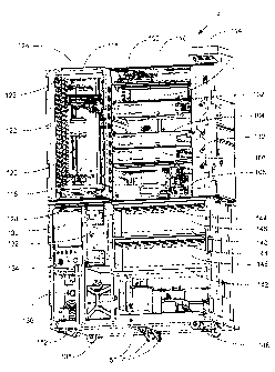
A perspective diagram of a working embodiment of the disclosed system is shown
in
FIG. 3. System 2 includes a vertical stack of workstations that includes, from
top to bottom, bar
code reader 100, combined de-paraffinizer/stainer 102, solvent exchanger 104,
convection oven
106, and coverslipper 108. In this embodiment, the workstations are connected
to electronics
backplane 110 (which can be seen at the back of the workstation bay that is
unoccupied and can
32
CA 02817698 2013-05-31
provide power and a data link to a system's computer). Combined de-
paraffinizer/stainer 102,
solvent exchanger 104 and coverslipper 108 also are connected to waste drain
112, which is part
of a fluidics manifold that supplies reagents to the workstations and drains
spent reagents from
the workstations. The workstations can be interchanged in position because in
this embodiment,
common connections are provided on the electrical and fluidic backplanes at
several of the bays.
Furthermore, this configuration permits rapid removal and replacement of
individual
workstations to aid reconfiguration (such as adding a second combined de-
paraffinizer/stainer to
increase system throughput potential) and repair (should a workstation fail or
need scheduled
maintenance). In other embodiments, one or more combined de-
paraffinizer/stainers can be
operated as combined de-paraffinizer/stainer/solvent exchangers and the
solvent exchanger is not
included. In such other embodiments, coverslipper 108 can further include
heaters to assist in
drying of slide trays by, for example, pre-heating the slide trays before they
are transported to
convection oven 106.
A dehumidifier 114 also is included in the embodiment of FIG. 3. The
dehumidifier can
lower humidity levels within the system to minimize moisture uptake by
reagents and reduce
condensation within the system. Adjacent to and to the left of the vertical
stack of workstations
is tranporter/elevator assembly 116 that occupies an elevator space. As can be
seen in the empty
bay of the vertical workstation stack, access ports are provided through which
slide trays can be
shuttled from the elevator space to the individual workstations in the
vertical stack.
Transporter/elevator assembly 116 includes X-Y shuttle table 118, and the
combination of the
elevator and the shuttle table comprises a particular embodiment of an X-Y-Z
transport
mechanism (X- left to right; Y- front to back; Z- up and down). Although not
shown in detail in
FIG. 3, X-Y shuttle table 118 is suspended from a cable that is connected to
counterweight 120.
33
CA 02817698 2013-05-31
In a particular embodiment, counterweight 120 is raised and lowered by a drive
screw, which in
turn is driven by a stepper motor. Sensors (not shown) can be placed adjacent
the elevator space
to detect the position of the shuttle table, and indexing of the shuttle table
at the sensor locations
provides precise control over the elevator position using stepper motors.
Adjacent to and in front of the transporter/elevator assembly 118 in FIG. 3 is
garage 122.
Above garage 122 in this embodiment is radiant heater 124. The topmost parking
station of the
garage thus comprises a baking workstation 126. A slide tray can be placed in
the baking station
126 underneath the radiant heater 124 to bake biological samples onto slides
held in the slide
tray. In a particular embodiment, radiant heater 124 has a heat profile that
provides substantially
uniform heating of the slides in the slide tray. Differences in heat
generating power/unit area
across radiant heater 124 compensate for differences in the distance of a
particular slide from the
edge of the slide tray. Otherwise, slides that are at the edge of the slide
tray would not be heated
to the same extent as slides near the middle of the tray due to greater heat
loss rates for slides on
the edges of the tray and the greater heating rates for slides in the middle
of the tray. Located
below garage 122 is portal assembly 128 through which slide trays can be
introduced to and
retrieved from the system.
Below both the garage, elevator/transporter assembly and the vertical stack of
workstations in FIG. 3 are several components that provide power, control and
reagents to the
system. In particular, printed circuit board 130 including a microprocessor
that controls, for
example, supply of reagents to the workstations and workstation functions.
Additional printed
circuit boards including microprocessors (not shown) on individual
workstations and the
elevator/transporter assembly further control the system. Limonene supply unit
132 (shown
without the removable limonene container) includes an RF1D antenna and sensors
for detecting a
34
CA 02817698 2013-05-31
fluid level in a removable container. Power supply 134 and pneumatics supply
136 provide
power and pressure/vacuum, respectively. A bulk alcohol supply 138 also is
shown.
On the right side of the lower portion of the system shown in FIG. 3 are 3
drawers of
components that together comprise a fluidics module for supplying reagents to
the system. Each
of these drawers can be slid out toward the front of the system to permit
access to additional
components at the back of the system that are hidden in the view of FIG. 3.
Two reagent
drawers, the upper reagent drawer 140 and the lower reagent drawer 142, each
include reagent
container slots 144 for holding a plurality of reagent containers (such as
keyed "bag-in-a-box"
containers discussed below) and a backpanel 146 that can include a plurality
of RFlD antennae
that can read RFID tags associated with the reagent containers, which, for
example, encode the
identity and expiration date of a particular reagent. The upper reagent drawer
140 and the lower
reagent drawer 142 also include pneumatic reagent pumps, valves and tubing
(not shown) to
supply reagents to one or more workstations in the vertical stack above. Below
the two reagent
drawers is fluidics drawer 148 that includes a plurality of pneumatic reagent
pumps 150. The
components of the system of FIG. 3 are contained in modular cabinet 152.
In operation, system 2 of FIG. 3 can simultaneously process several slide
trays, each of
which carries a plurality of slides (such as a plurality of slides held in a
substantially horizontal
position). A user loads a slide tray into the system through portal assembly
128.
Elevator/transporter then retrieves the slide tray from the portal assembly
128. Once the slide
tray is pulled from the portal assembly 128 onto X-Y shuttle table 118, the
slide tray can be
moved to any of the workstations or placed in a parking station of the garage
to await retrieval at
another time.
CA 02817698 2013-05-31
Although a particular slide tray can be processed according to any arbitrary
user-defined
or pre-defined set of operations, a particular sequence of operations includes
first taking a slide
tray to barcode reader 100 where slides in the tray are detected by optical
sensors on a partition
between the transporter space and the code reader and any barcodes on detected
slides are read
by the code reader. The slide tray is then moved to baking station 126 where
biological samples
on the slides are heated under radiant heater 124. The baking step can be
used, for example, to
adhere the samples to the slides and/or to melt an embedding material in the
sample. It has been
surprisingly discovered that baking the slides under radiant heater 124
greatly aids removal of
paraffin from paraffin-embedded tissue samples, as it tends to melt and spread
the paraffm in the
sample across the surface of the slide. The thin layer of paraffin, having
greater surface area
now that it has spread across the slide, is more easily removed by a paraffin-
dissolving solvent
such as limonene, making it possible to remove the paraffin with the solvent,
without either
heating the solvent before it is applied to the slide or after it has been
applied to the slide. Once
the slides have been baked, the slide tray is moved to combined de-
paraffinizer/stainer 102
where the biological samples on the slides in the slide tray are de-
paraffmized if necessary and
stained. Since many staining protocols make use of aqueous-based solvents, and
coverslipping,
of a sample is best accomplished once water in the sample has been removed,
the slide tray is
then moved to solvent exchanger 104 where the sample is treated with a series
of solvents to
remove water and prepare the slides for coverslipping. In an alternative
embodiment, solvent
exchange also is performed in workstation 102, which can function to de-
paraffinize, stain and
solvent exchange samples.
It also has been surprisingly discovered that it is possible to apply a
controlled amount of
a solvent that is compatible with coverslipping (such as limonene) in solvent
exchanger 104 and
36
CA 02817698 2013-05-31
use that solvent in a coverslipping operation once the slide tray has been
moved to coverslipper
108, thereby reducing system complexity in a particular embodiment since the
coverslipper 108
can be operated without the need to supply it with fluids. Thus, in this
particular embodiment,
the slide tray is moved from solvent exchanger 104 (with an amount of a
coverslipping
compatible solvent on its top surface) to coverslipper 108. Once coverslips
are placed onto the
slides in coverslipper 108, the slide tray can then be moved to convection
oven 106 to cure the
coverslip onto the slides (at least partially) and also to dry the tray itself
(at least partially). A
particular advantage of a disclosed system and a method in which slides are
cured in an oven
after coverslipping (for example, either a convection oven or a radiant oven)
is that even if the
coverslipping solvent underneath the coverslip is not completely removed, a
skin of glue forms
around the coverslip, which holds the coverslip in place during subsequent
handling by a health
care professional such as a pathologist. Processing slides held in a
substantially horizontal
position aids curing since the large exposed surface area of the slides
facilitates quick and
efficient removal of solvents from slide surfaces. Once the slides are cured
and the tray dried,
the slide tray can be moved back to portal assembly 128 for retrieval by a
user. Parking garage
122 can be used to store slide trays at any point during the series of slide
processing operations,
and as is described below, computer control of the sequence of
movements/operations can
maximize workflow by helping to ensure that workstations are not idle because
no slide tray is
available for processing therein.
As described previously, a plurality of slides can be held (such as in
substantially
horizontal positions) in a slide tray. The slide tray may have any shape, and
the slides held in a
slide tray can be arranged in any manner. In addition, the slide tray can be
configured to hold
any number of slides, for example, 5 or more slides, 10 or more slides, 20 or
more slides, or even
37
CA 02817698 2013-05-31
30 or more slides. Several examples of slide trays of different shapes,
holding slides in various
arrangements, are shown in top view in FIGS 4A through 4F. Fig. 4A shows a
rectangular tray
holding two rows of slides that are held side-by-side on both sides of the
central long axis of the
slide tray so that the long dimensions of the slides are disposed outward from
the long central
axis of the tray. Fig 4B shows a circular slide tray with slides held in
radial positions with their
long dimensions disposed inward from the outer edge of the tray toward the
center of the tray.
FIG. 4C shows another rectangular tray holding two rows of slides that are
held side-by-side on
both sides of the central long axis of the slide tray. FIG. 4D shows a square
tray holding two
rows of slides. FIG. 4E shows a rectangular tray holding three rows of slides,
where slides are
held such that their long dimensions are parallel to the long axis of the
tray. FIG. 4F shows a
larger, rectangular tray holding 4 rows of trays, with the slides held side-by-
side in the four rows
such that the long dimensions of the slides are disposed in the direction of
the short axis of the
tray.
38
CA 02817698 2013-05-31
IV. System Components/System Operation
A. Slide Tray
A particular embodiment of a slide tray that can be used in the disclosed
system is shown
in FIG. 5. Rectangular slide tray 200 having side walls 202, 204 and bottom
206 includes a
specimen slide supporting rack 208 for holding a plurality of specimen slides
210 in a
substantially horizontal position in the same plane. Holding all the slides in
separation and in
essentially the same substantially horizontal plane facilitates baking and
drying can prevent
cross-contamination of slides during de-paraffinizing, staining, washing and
solvent exchanging,
and other steps that involve dispensing reagents to slide surfaces. Rack 208
includes a plurality
of slide spring supports 212 that limit the axial, lateral and vertical
movement of specimen slides
210 once placed on the slide tray. Rack 208 snaps into tabs 214 and is
supported above tray
bottom 206 at sufficient height to minimize or prevent the formation of films
or bubbles between
the specimen slide bottom and the tray bottom. Slide spring supports 212 hold
the individual
specimen slides in position by exerting force on opposing sides of the
specimen slides 210. The
floor 206 of the slide tray is sloped towards nadir 216 in the middle of the
tray. Spent reagents
dispensed to slides that accumulate in nadir 216 can then be aspirated from
the tray as will be
described in detail below with reference to the description of particular
embodiments of the
system's workstations. Optional splash guard 218 can be added to further
inhibit transfer of
reagent from one slide to another. Tray 200 can be used for automated handling
of a plurality of
specimen slides through of the steps of drying/baking, de-paraffinizing,
staining and
coverslipping using workstations configured to treat the slides as they are
held in the tray's
particular configuration. In the embodiment of FIG. 5, slide tray 200 is
configured to
39
CA 02817698 2013-05-31
accommodate 16 specimen slides arranged in a generally horizontal grid of two
rows of slides,
each of which rows contain eight slides.
A second embodiment of slide tray 200 is shown in top perspective view in FIG.
6. In
this embodiment, the rectangular slide tray having side walls 240 and end
walls 242 further
includes end hooks 244 and side hook 246 that can be engaged by a transporter
as the slide tray
is moved within the disclosed system. Slides 248 are held in the tray by slide
clip pillars 250 and
supported by slide support pillars 252. Optional slide end support tabs 254
also are shown in
FIG. 6. Bottom 256 slopes from side walls 240 toward the center of the tray.
An opening 258 in
one end wall 242 is provided, and it is at this opening that a wicking member
can contact the
bottom 256 to break the surface tension of any liquids collected in the slide
tray, thereby
facilitating drainage of such liquids from the slide tray, especially if the
slide tray is tipped in the
direction of opening 258. In a particular embodiment, slides 248 are held
substantially
horizontal in the tray (when the tray itself is placed on a horizontal
surface), and in more
particular embodiments, the slides slope slightly downward (decline) from the
slide clip pillars
250 to slide support pillars 252, for example, at an angle between about 0.2
degrees and 0.8
degrees from horizontal, such as angles between about 0.3 degrees and about
0.7 degrees, for
example angles between about 0.4 degrees and about 0.6 degrees. A small angle
of decline
toward the sides of the tray is surprisingly helpful for removal of reagents
from the slide surfaces
during certain slide processing operations, yet does not prevent substantially
even distribution of
reagents across the slides upper surfaces. The side and end walls of a tray
can rise to a level
below the level of slides placed in the tray, can rise to the same level as
slides placed in the tray
or can rise above the level of slides held in the tray. Side and end walls
that rise above the level
of slides held in the tray can have the advantage of reducing splashing of
reagents over the sides
CA 02817698 2013-05-31
of the tray, and can eliminate the need for additional splash guards within a
workstation, such as
the optional splashguards discussed below with respect to the nozzle manifold
of FIG. 14.
A bottom perspective view of the slide tray of FIG. 6 is shown in FIG. 7 to
illustrate
further the features of this particular embodiment of slide tray 200. The
slope of bottom 256
toward the center midline of the slide tray is clearly visible in FIG. 7. An
end hook 244 and side
hook 246 also are shown. Additional features of slide tray 200 not shown in
FIG. 6 include
magnet 260 that can be used in conjunction with one or more Hall-effect
sensors placed in one or
more locations (such as in one or more workstations) in the disclosed system
to detect when the
slide tray occupies those locations. Tabs 262 and indents 264 at the comers
(not all shown) of
the tray can be used to stack several trays on top of one another without the
slides touching so
trays can be stored without taking up more laboratory bench space than
necessary. Slide tray
200 can be constructed of any material including a metal (such as aluminum,
magnesium or a
lightweight metal alloy) or a plastic (such as ABS or a thermoplastic), and
can be formed, for
example, by machining, casting or molding. In a particular embodiment,
lightweight slide trays
are cast in magnesium and then covered with a tetrafluoroethylene, non-stick
coating. Slide clip
pillars 250, slide support pillars 252 and slide support tabs 254 can be
formed at the same time as
the tray (such as when the tray is cast) or added later, for example, by being
glued into place.
FIG. 8 shows several different embodiments of slide clip pillar 250 and a
close-up of a
particular embodiment of a slide support pillar 252. FIG. 8A shows a slide
clip pillar 250 having
a spring clip 270 that is held to the slide clip pillar with screw 274. As was
shown in FIG. 6,
each slide is supported at one end by two slide clip pillars, one on each side
of the slide. Spring
clip 270 holds one edge of a slide against a slide support shelf 272. Slides
are loaded into the
tray by sliding them from the side of the tray and under the spring clips on
adjacent slide clip
41
CA 02817698 2013-05-31
pillars. The alternative embodiment of slide clip pillar 270 shown in FIG. 8B
is a type of slide
clip pillar that can be top-loaded by a user. In this alternative embodiment,
a slide is pushed past
the upper end of spring clip 270 to rest on slide support shelves 272 and is
held there by the
spring clip. Again, the spring clip 270 is held to the pillar with a screw
274. Another
embodiment of a spring clip pillar 250 that is side-loaded by a user is shown
in FIG. 8C. In this
particular embodiment, the slide clip 270 includes a rigid top portion 276 and
a flexible lower
portion 278, where the slide clip is again held in place on the pillar by
screw 274. As a slide is
introduced into the slide clip 270, flexible lower portion 278 deflects toward
spring clip support
273. Spring tension holds the slide firmly under the rigid top portion 276.
Another embodiment
of a side-loading slide clip pillar having a slide clip 270 with a rigid top
portion 276 and a
flexible lower portion 278 is shown in FIG. 8D. In this embodiment, as a slide
is introduced,
flexible lower portion again is deformed, but the deflection is not limited by
contact with spring
clip support 273 as in the previous embodiment. Spring tension holds the slide
firmly under
rigid top portion 276. A screw 274 can be used to secure the clip to the
pillar portion. FIG. 8D
also shows that a rigid top portion 276 can have an upward bend in the
direction from which a
slide is introduced into the clip that directs a slide toward the flexible
lower portion 278, thereby
aiding in deflection and loading of spring tension in the clip.
A close-up of slide support pillar 252 is shown in FIG. 8E. Slide 248 rests on
support
surface 280. The distance from the support surface to the top of the pillar
can be made such that
the top surface of slide 248 is above (as shown) and not in direct contact
with slide support pillar
252. This arrangement is advantageous as it helps prevent wicking of reagents
from the top
surface of the slide. Again, as was shown in FIG. 6, each slide is supported
by two such slide
support pillars, one on either side of the slide. In another embodiment that
is not illustrated, a
42
CA 02817698 2013-05-31
single slide support pillar can be placed under the slide with the same
advantage that it does not
create a wicking path from the top surface of the slide. Additional
embodiments of slide trays
that can be used in the disclosed system are described in U.S. Patent
Application
Publication 20040091395 filed July 16, 2003.
B. Drying Oven
A drying oven, which includes a thermally insulated compartment and a heat
source, can
be used to cure slides after coverslipping (to set the coverslips in place and
thus prevent their
inadvertent removal during slide handling by a user) and to dry slide trays
before they are
retrieved from the disclosed system by a user. In one embodiment, as shown in
FIG. 9A, drying
oven 300 includes a top portion 302 and a bottom portion 304 that form a
compartment that
receives a slide tray. A convection heat source 306 (including one or more
heating elements and
one or more blowers) configured to blow heated air across the slides is
located at the back of the
slide tray receiving compartment. An insulating layer 308 can be included to
reduce heat loss
from the drying oven workstation, thereby increasing its thermal efficiency.
A second embodiment of the drying oven 300 is shown in FIG. 9B, and again
includes a
top portion 302 and a bottom portion 304 that together form a compartment that
receives a slide
tray. In this embodiment, the convection heat source is positioned above the
slide tray
compartment rather than at the back of the workstation as in the embodiment of
FIG. 9A. The
convection heat source includes blower 309, heat directing shield 310
(configured to circulate
heated air evenly across the slides in a slide tray) and heating element 312.
A slide tray tilt pan
assembly 314 receives the slide in the compartment of the drying oven and can
hold the slide
tray firmly in position, for example, with one or more springs that gip the
side of a slide tray as
43
CA 02817698 2013-05-31
it is pushed into the drying oven by a transporter. In a particular
embodiment, slide tray tilt pan
assembly 314 includes a wicking member (not shown in full view) that contacts
an edge of the
bottom of a slide tray at an opening in an end wall and a tilting mechanism
(not shown) that tilts
the tilt pan assembly to drain the slide tray toward the rear of the
workstation. Draining of a
slide tray reduces the fluid volume that must be evaporated by the
workstation. Thus, a pan 316
is provided to accept any liquids such as residual reagents that are drained
from a slide tray as it
is tipped in the workstation. The pan can include a drain tube (not shown) to
carry liquids away
from the workstation, and a overflow condition sensor 318 such as a thermistor
to detect an
overflow condition in the workstation that could occur, for example, if the
drain tube became
clogged. In addition, drying oven 300 can further include a sensor, such as an
optical or Hall-
effect sensor, that detects the presence of a tray in the workstation. One
advantage of a
horizontal presentation of slides in a slide tray is that convection drying is
particularly efficient
since liquids tend to spread across slides, and the greater surface area of
the liquid aids in its
evaporation. A heat sensor also can be included and used in a feedback control
loop with the
heating element to maintain a particular temperature within the drying oven,
for example, to
prevent excessive heating of the slides that could damage the biological
specimens that they
carry.
As was discussed with respect to FIGS. 2 and 3, the workstations of the
disclosed system
can include standardized data and power plugs that mate with corresponding
plugs on an
electronics manifold so that individual workstations can be interchanged in
position within the
system. Such a standardized power and data plug 320 is shown in the embodiment
of FIG. 9B.
In some embodiments, a convection drying oven can also function as a baking
station for slides
in an initial baking operation in a set of automated slide processing
operations.
44
CA 02817698 2013-05-31
C. De-paraffinizer/Combined Baking Oven and De-paraffinizer
FIG. 10 shows a particular embodiment of a de-paraffinizer workstation that
can be
optionally configured to also function as a baking station, for example, to
aid in de-paraffinizing
biological specimens on slides. De-paraffinizing station 400 comprises a
compartment having a
top portion 402 and a bottom portion 404 into which a slide tray 406 holding a
plurality of slides
can be receiveed, and within which one or more slide processing operations can
be performed.
In this embodiment, dispense manifold 408 having a plurality of dispense
nozzles 410 is
positioned above a slide tray docked in the workstation. The dispense nozzles
410 are
configured to dispense reagents onto and along the top surfaces of the slides
toward the sides of
the slide tray, thereby minimizing the potential that reagent reaching one
slide will thereafter
contact another slide. Dual rinse manifolds 412 including rinse nozzles
positioned to dispense
another reagent such as deionized water also are included in the illustrated
embodiment. In
operation, a de-paraffinizing reagent is dispensed to the slides in the slide
tray, and collects in the
bottom of slide tray 406. Aspirator 414 can be positioned to remove the
accumulating reagent
from the slide tray.
In a particular optional embodiment, aspirated de-paraffinizing reagent is re-
circulated by
pump 416 and heated in heaters 418 before it is again dispensed from the
dispense nozzles 410 in
manifold 408. Filter 420 can be used to remove any cells that might become
dislodged from the
biological specimens on the slides before the reagent is reapplied to the
slides, thereby
minimizing the potential for cross-contamination of slides. It should be
understood, however,
that the use of fresh reagent each time a reagent is applied to a slide is the
optimal approach.
CA 02817698 2013-05-31
In a more particular embodiment, optional radiant heater banks 422 also are
included in
the workstation, and these heater banks can be used to heat up the slides that
rest below them
when a slide tray is docked in the workstation. As such, the workstation
becomes a combined
de-paraffinizer and baking station. As mentioned previously, a baking station
can melt and
spread paraffin in a biological sample over a greater surface area, thereby
facilitating its removal.
The radiant heater banks 422 can be used alone, or in combination with
recirculation and heating
in heaters 418. If desired, accumulated paraffin in the reagent stream can be
removed from the
re-circulating fluid, for example, by skimming the paraffin from the top or
bottom of the fluid,
depending upon whether the de-paraffinizing reagent is more or less dense,
respectively, than the
liquefied paraffin.
Pre-heating the slides, i.e., to soften the paraffin, improves the efficiency
of the de-
paraffinizing step. Depending on ambient conditions and the amount and type of
wax, it may be
sufficient to apply the de-paraffinizing fluid to the pre-heated slides, let
the fluid work for a few
seconds or minutes, and then wash the fluid and wax from the slides using, for
example,
deionized water dispensed from rinse nozzles 412. If necessary, the de-
paraffinizing fluid
covered slides can be baked for several minutes or more, for example, about 5
minutes, before
being washed. Thus, the de-paraffinizing process is enhanced. Moreover, less
de-paraffinizing
fluid can be used, and it may not be necessary to filter and recycle de-
paraffmizing fluid. Rather,
the spent de-paraffinizing fluid may be passed directly to drain, or filtered,
and then passed to
drain.
Various de-paraffinizing agents can be used in the workstation, and can
comprise, for
example, aqueous-based fluids such as disclosed in U.S. Patent Nos.6,544,798
and
6,855,559, including deionized water, citrate buffer
46
CA 02817698 2013-05-31
(pH 6.0 ¨ 8.0), tris-HC1 buffer (pH 6 ¨ 10), phosphate buffer (pH 6.0 8.0),
FSC buffer, APK
washTM, acidic buffers or solutions (pH 1 ¨ 6.9), and basic buffers or
solutions (pH 7.1 ¨ 14). If
desired, the aqueous-based fluid may also contain one or more ionic or non-
ionic surfactants
such as Triton X-100Tm, Tweenl-m, Brij, Saponin and Sodium Dodecylsulfate. The
de-
paraffinizing fluid can be heated, however this is optional, especially if
radiant heaters 422 are
included in the workstation and employed in the de-paraffinization process.
For example, if the
embedding medium is paraffin, which has a melting point between 50 ¨ 57
degrees C, the fluid
can be heated to a temperature greater than the melting point of paraffin,
e.g. between 60 ¨ 70
degrees C. Typically, the fluid is heated in the fluid supply. The use of
heated aqueous de-
paraffinization fluids is described in more detail in U.S. Patent No.
6,544.798.
= Alternatively, any non-aqueous de-paraffinizing fluid such as limonene,
xylene or an
alkane-based fluid (such as an n-alkane or isoalkane, or a mixture thereof),
or a combination thereof, can be used. While conventional de-paraffinizing
fluid such as xylene may be used, one particular de-paraffinizing fluid that
has been used in a
working embodiment of the disclosed system is D-Limonene, which is a
hydrocarbon of the
monoterpene group having a molecular formula C10l416. D-Limonerie, which has
been used in
the food and cosmetic industry for many years is non-toxic, and has become a
preferred
replacement for xylene in pathology laboratories. D-Limonene is commercially
available from a
variety of sources under various names including Safsolvent (Ajax Chemicals,
Auburn, NSW,
Australia), Hemo-De (PMP Medical Industries, Los Angeles, CA), Histo-clear
(National
Diagnostics, Manville, NJ), BDH xylene substitute (BDH Chemicals Ltd.,
Toronto, Ontario,
47
CA 02817698 2013-05-31
Canada), and AmeriClear (Baxter Health Care Diagnostics Inc., McGraw Park,
IL). D-
Limonene performs well as a paraffin solvent and cleaning agent, and also may
present a reduced
fire risk compared to xylene.
D. Radiant Heater/Baking Station
As discussed previously, a radiant heater can be used to bake biological
specimens onto
slides and/or to soften and spread paraffin in paraffin-embedded tissue
specimens as an aid to
paraffin removal. Although a baking station can be located anywhere in the
disclosed system
(for example, as a discrete workstation in a vertical stack of workstations)
in the particular
embodiments of FIGS. 2 and 3, a radiant heater is placed above the uppermost
parking station in
the garage portion of the system, and this parking station thus functions as
the baking station. If
the baking station is located in the garage adjacent to the code reader, it
helps to minimize
handling of the tray by the transporter and also helps to minimize the amount
of moisture that
accumulates in the system as water is driven off of biological specimens.
Temperature in a
baking station can be controlled by measuring the temperature with a
temperature probe such as
a thermocouple, which can provide feedback control of the amount of heat
generated by the
radiant heater.
In a more particular embodiment, the radiant heater is configured to provide
substantially
uniform heating of slides held in a slide tray. A general method by which the
heating profile of a
radiant heater can be configured is discussed below using the particular
example of a rectangular
slide tray holding a plurality of slides in a substantially horizontal
position.
In general, in order to radiantly heat a tray full of slides substantially
uniformly with a
radiant heater of finite size, the temperature of the radiant heater needs to
be hotter around the
48
CA 02817698 2013-05-31
edges than in the center since heat loss from the edges of the heater occurs
at a higher rate than in
the center of the radiant heater, and because the slides in the center get
heat from both sides
while the slides near the edges get heat only from one side. FIG. 11A
illustrates relevant
parameters used to determine a heat profile of a radiant heater 440 that will
heat slides 442 in a
substantially uniform manner.
Advantageously the heater is sized to overlap the outer edges of the slides as
far as
possible, in this case by amount "a". The heater plate is displaced by
distance "c" above the
slides. A temperature distribution as a function of X along the heater plate
that produces uniform
radiant heat flux as a function of Y is desired.
The effective area of a narrow strip on the slide, dY, as seen from X is dY
cos(0),
therefore, the radiant heat energy falling on a slide at Y on a strip of width
dY from a strip at X
on the heater of dX width is:
dq = I dX r d0 cos(0)
where dq = energy falling on strip dY wide emanating from dX, I = intensity of
radiation
(and I = k T4), where T is the absolute temperature in Kelvins.
From geometry this can be reduced to:
dq = k T4 dX dY c2 / [ (c-y.)2 e2
For a fixed value of Y on the slide, dq(Y) is calculated as an integral over
all X on the
heater (from ¨a to X max).
49
CA 02817698 2013-05-31
Xmax
e
dq(Y) = k -a
Tx4 [ c2 / { ( Y ¨ X) + c2} 1 dX
A distribution of Tx such that dq(Y) is the same for all Y is desired, i.e.,
the amount of
heat impinging on any part of any slide should be substantially the same. A
solution can be
found if some temperature distribution is assumed, thereby allowing the
equation above to be
numerically integrated. A temperature distribution that works well for solving
the equation is an
error function where the temperature is maximum at "¨a" and asymptotically
approaches a
constant value somewhere inside the edge of the first slide. A similar
analysis is then performed
to find the heat distribution required in the heater to produce the desired
temperature distribution.
This also is an error function, but surprisingly can be approximated by a
linearly decreasing heat
load. FIG. 11B shows a heat distribution (Z represents the magnitude of heat
production from
the radiant heater) of a nearly rectangular heater used in a working
embodiment of the disclosed
system. The heat production is uniform over the central region 444, then
linearly increases near
the edges to a maximum value 446, as indicated. At the corners, the heat
increases linearly in
both directions, giving rise to the peaks at the corners 448. As positioned in
a working
embodiment of the system, the comers of the otherwise rectangular heater had
to be cut off for
the heater to fit within the system's cabinet frame, giving rise to the
truncated comers 450 of the
heat profile. However, the cut comers overhung the slide tray in the baking
station by sufficient
distance that the lower heat production at these cut corners did not
significantly affect heating
uniformity across slides. Experimental testing of the heater showed that the
slide temperature
CA 02817698 2013-05-31
was uniform to within about 2 K (such as within 1 K) over all slides in a tray
positioned below
the radiant heater.
E. Stainer/Combined de-paraffinizer and stainer/Combined stainer,
de-paraffinizer
and solvent exchanger.
A workstation is provided that can be used to apply one or more reagents to
slides during
one or more slide processing operations. Since the workstation typically
includes one or more
nozzles, and more typically one or more banks of nozzles, the workstation is
actually a highly
versatile workstation that can function not only as a workstation for applying
staining reagents to
slides, but also for applying de-paraffinizing, wash and solvent exchange
reagents or any other
type of reagent used in a particular slide processing operation. Thus, the
workstation can also be
used as a de-paraffinization workstation and/or a solvent exchange
workstation. In a working
embodiment of the disclosed system, a single workstation functions as a
combined de-
paraffinizer/stainer, and in another working embodiment, a single workstation
functions as a
combined de-paraffinizer/stainer/solvent exchanger. In performing each of
these functions,
multiple reagents can be applied in any particular series to slides held in a
slide tray without
moving the slides to another workstation.
FIG. 12 shows a particular embodiment of a stainer 500 that includes a top
portion 502
and a bottom portion 504 that form a compartment housing a nozzle manifold 506
(including one
or more nozzles, or banks of nozzles, such as at least two banks of nozzles,
for adding reagents
simultaneously to a pair of slides held in a slide tray) that is mounted on
rail 508 and driven back
and forth along the rail 508 by a drive screw (not shown) and stepper motor
510 combination so
that it can be moved into position over a pair of slides held in a slide tray
like the one illustrated
51
CA 02817698 2013-05-31
in FIGS. 5 and 6. Valve block 512 is connected to the nozzle manifold 506 and
functions to
control the type of reagent that is dispensed from the nozzle manifold. Excess
reagent that
collects in slide tray 200 is removed from the tray in this embodiment by
aspirator 514 that
includes distal end 516 that is dipped to the bottom of the slide tray. Pump
518 then removes
spent reagent from the tray through aspirator 514.
FIG. 13 shows a working embodiment of workstation that can be used as a
combined de-
paraffinizer/stainer, or can be used to de-paraffinize, stain and solvent
exchange. FIG. 13 shows
such a workstation from a bottom perspective view. Workstation 501 includes a
top portion 502
and a bottom portion 504 that form a comp& talent housing a rail 508 along
which a nozzle
manifold (not shown in FIG. 13, see FIG. 14) that is mounted to nozzle
carriage 520 is driven
back and forth within the workstation compartment by screw drive 509 and
stepper motor 510.
Valves 512 switch the reagent stream that is applied to slides through the
stainer nozzle between
different reagents and air during operation. Although the fluidics connections
(such as hoses) are
not shown in FIG. 13, these connections can be made through energy chain 522
that is attached
to nozzle carriage 520. Attached to the lower portion 504 of the combined de-
paraffinizer/stainer is drain pan 524 that is connected to drain tube 526,
which can be used to
carry spent reagents away from the workstation. An overflow sensor 528 such as
a thermistor
that can detect an overflow condition within the drain pan also can be
included.
As was discussed with reference to FIGS. 2 and 3 workstations can be
configured to
include common electronics connections and fluidics connections such that
workstations can be
interchanged in position or replaced quickly and easily. The workstation of
FIG. 13 includes
data and power plug 530 configured to plug into an electronics manifold and
fluidics interface
532 that includes a plurality of connectors that mate with corresponding
connectors on a fluidics
52
CA 02817698 2013-05-31
manifold. In a particular embodiment, the connectors on the workstation are
male connectors
that can be drawn tightly into a corresponding set of female connectors on a
fluidics manifold
using screws 534, thereby providing a tight seal between the fluidics
interface 532 and a fluidics
manifold.
FIG. 14 shows a bottom perspective view of a working embodiment of a nozzle
manifold
506 that can be used to apply reagents/pressurized air to pairs of slides held
in each of two rows
in a slide tray like the one shown in FIG. 6. Nozzle manifold 506 includes
dispense nozzles 550,
forward top surface rinse nozzles 552, backward top surface rinse nozzles 554,
jet drain nozzles
556 (see, for example, U.S. Patent No. 6,472,217), bottom surface rinse
nozzles
558 and splashguards 560. In operation, nozzle manifold 506 is
attached to nozzle carriage 520 of FIG. 13 and is moved over pairs of slides
in a slide tray along
rail 508 by stepper motor 510. Dispense nozzles 550 can be used to deposit
reagent solutions
onto the tops of slides, and air can be forced out of the same to distribute
the reagent across the
slide or even blow some of the reagent off of a slide. Forward top surface
rinse nozzles 552 can
be used to apply reagents to slides, for example, deionized water or other
solvents, and air also
can be forced through these nozzles to assist with spreading of reagents
across the surface of a
slide, to assist with clearing of liquids from the slide, or to clear reagents
from the lines leading
to the nozzles. In a particular embodiment, the angle of the forward top
surface rinse nozzles
552 is such that streams of reagent exiting these nozzles will impinge on the
top surface of a
slide at an angle of between about 20 degrees and 30 degrees from the slide
surface, for example
at an angle of between about 22 degrees and about 28 degrees such as an angle
of between about
24 degrees and about 26 degrees. Such angles of impingement are advantageous
for reducing
skipping of reagents past portions of the slide surface and for reducing the
splashing of reagents
53
CA 02817698 2013-05-31
off of the slide surface (which might, for example, cause cross-contamination
of slides).
Backward top surface rinse nozzles 554 can be used, for example, to rinse
reagents from a label
portion of a slide. Air can also be directed through these nozzles to assist
reagent removal, or to
remove any reagent in the lines leading to the nozzles. In a particular
embodiment, the backward
top surface rinse nozzles are configured to deliver reagents so that they
impinge on the top
surface at an angle of between about 20 degrees and about 50 degrees relative
to the slide
surface, for example, an angle of between about 25 degrees and about 45
degrees such as an
angle of between about 30 degrees and about 40 degrees. Again, such angles are
advantageous.
In a particular embodiment, streams of reagent from the backward top surface
rinse nozzles are
used in combination with streams of reagent from the forward top surface
nozzles to produce
"walls" of reagent solution, which travel down the slide and very effectively
rinse the slide
surface. In this particular embodiment, the forward top surface rinse nozzles
and the backward
top surface rinse nozzles can be configured to apply reagents to the slide at
substantially the
same position on the slide. By continuously streaming reagent (such as de-
ionized water) from
the forward top surface rinse nozzle and pulsing reagent from the backward top
surface rinse
nozzle a moving "wall" of reagent can be formed. The "wall" forms during the
time when both
sets of nozzles are on, and as a result of their opposing directions of flow
at their intersection.
When the backward top surface rinse nozzles are pulsed off, the wall of
reagent then travels
down the slide in the forward direction. Jet drain nozzles 556, which direct
streams of reagent
(such as de-ionized water) toward a slide near its edge, for example, within
about 0.0200 in. of
the edge of a slide, can break the surface tension of liquids on the slide and
help draw such
liquids off of the slide (for example, off the short edges of the slides near
the side walls of the
slide tray as shown in FIG. 6). Typically, jet drain nozzles 556 are directed
toward the surface of
54
CA 02817698 2013-05-31
a slide at its edge at an angle of less than 90 degrees, for example, at an
angle of less than 45
degrees such as an angle of about 20 degrees. In a particular embodiment, jet
drain nozzles 556
can be pulsed to coincide with the arrival of the "wall" at the slide's edge.
Bottom rinse nozzles
558 can be used to remove reagent (such as staining reagents) that cling to
the bottom surface of
a slide during slide processing operations, and enable a method of rinsing the
bottom of a slide
during a slide processing operation. Splash guards 560 function to help
prevent reagents from
splashing out of the slide tray and into the workstation. They also can serve
to reduce or
minimize the potential for cross-contamination between slides in a slide tray.
Although in the
illustrated embodiment, the nozzle is designed to be moved into position over
a pair of slides (or
into a position over particular portions of a pair of slides) held in a slide
tray, it is to be
understood that a smaller moveable nozzle assembly that is moved to various
positions over
individual slides or a larger moveable nozzle assembly that is moved to
positions over larger
groups of slides (such as 3, 4, 5, 6 or more slides) are contemplated.
FIG. 15 shows a representative schematic of a fluidics system that can supply
reagents
and pressurized air to the nozzle manifold of FIG. 14 for automated de-
paraffinization and H&E
staining (and in some instances solvent exchange) of biological samples placed
on microscope
slides. Reagent/air supply 570 (including, for example, the fluidics module
discussed in detail
below) includes pressurized air supply 572, deionized water supply 574, rinse
solution supply
576 (for example a supply of a surfactant solution such as a 0.1% Tween 20
solution), a first
concentration hematoxylin solution supply 577, an alcohol (typically ethanol)
supply 578, an
eosin solution supply 580, a second concentration hematoxylin solution supply
582, a bluing
solution supply 584, a limonene supply 586 (or a supply of any other de-
paraffinizing reagent
such as those discussed above) and an acid solution supply 588. The various
individual reagent
CA 02817698 2013-05-31
supplies and the air supply included in reagent/air supply 570 can be
connected as shown to one
or more of a dispense manifold 590, a hematoxylin select valve 591 and a rinse
manifold 592.
Selection of reagents/air for delivery to slides is performed using valves in
the dispense manifold
590, the hematoxylin select valve 591 and valves the rinse manifold 592.
Selection can be
performed under computer control. In some circumstances, more than one reagent
can be
introduced into the same line (continuously or in pulses) to provide mixtures
of reagents, for
example, deionized water/alcohol mixtures, and mixing chambers (such as inline
mixing
chambers) can also be included. Note that at least some of the nozzles on the
two sides of the
nozzle assembly are separately plumbed, making it possible to apply a reagent
to only one slide
in a pair of slides on opposite sides of a slide tray. Thus, a reagent can be
applied to two slides in
an opposed pair in series or simultaneously. Or, if no slide was detected in a
position in a tray,
no reagent need be applied to that position while a slide in an opposed
position can be treated. In
other embodiments, each different type of nozzle in a nozzle assembly can be
separately
plumbed or all nozzles of a particular type can be plumbed together,
Reagents/air are supplied to particular nozzles or sets of nozzles in nozzle
manifold 506
(see discussion of FIG. 14) as shown in FIG. 15. Reagents are supplied to the
jet drain nozzles
through jet drain nozzle inlets 593, to backward top surface rinse nozzles
through backward top
surface rinse nozzle inlets 594, to dispense nozzles through dispense nozzle
inlets 595, to
forward top surface rinse nozzles through forward top surface rinse nozzle
inlet 597 and to
bottom surface rinse nozzles through bottom surface rinse nozzle inlet 599.
56
CA 02817698 2013-05-31
F. Solvent Exchanger ;
Most biological stains that are commonly used are aqueous or aqueous/alcohol
based.
Thus, biological samples such as paraffin-embedded tissue samples are first de-
paraffinized and
hydrated before staining since aqueous-based stains cannot penetrate paraffin
and stain tissue
components. Conversely, the fluids used to dissolve coverslip adhesives and
mount coverslips
onto microscope slides are generally immiscible with water. Therefore, after a
biological sample
has been stained, the water that remains in the sample is first replaced with
a non-aqueous based
fluid compatible with coverslipping before the sample is coverslipped. This
function can be
accomplished in a solvent exchanger workstation.
A working embodiment of a solvent exchanger is shown in FIG. 16. However, it
should
be understood that such a workstation can also perform additional slide
processing operations,
for example, staining or de-paraffinizing, either as shown or with some
modification. The
solvent exchanger 600 of FIG. 16 includes a top portion (not shown for
clarity) and a bottom
portion 602 that form a compartment that receives a slide tray and is
configured to perform one
or more slide processing operations. A nozzle manifold 604 (including one or
more nozzles or
banks of nozzles, for example, dispense nozzles as in the embodiment of FIG.
14) further
includes a pair of blow-off nozzles 606. The nozzle manifold 604 is attached
to nozzle carriage
608, which is itself attached to rail 610 (which can be attached directly to
the unseen top
portion). The nozzle manifold 604 attached to nozzle carriage 608 is moved
along rail 610
within the workstation by stepper motor 612 coupled to screw drive 613 by
drive coupling 614.
Reagents are supplied to nozzle manifold 604 through tubing (not shown) that
is directed through
energy chains 616 so that the tubing does not interfere with the movement of
the nozzle manifold
604 over successive pairs of slides in slide tray 618.
57
CA 02817698 2013-05-31
As shown in FIG. 16, a slide tray 618 is held in the workstation in tilt pan
620. A Hall-
effect sensor 622 is mounted on lower portion 602 of the workstation to detect
the presence-of
slide tray 618 in its proper position in the workstation (which can be used to
alert the system's
computer to begin a slide processing operation because the slide tray is
properly positioned or to
suspend the slide processing operation because the slide tray was not properly
received into the
workstation). Hall-effect sensor 622 detects the tray in the workstation by
detecting the presence
of magnet 624 which is mounted in a recess on the side of slide tray 618. Tilt
pan 620 includes
wicking plate 626 that contacts the opening in the end wall of slide tray 618,
which aids in
removal of spent reagents from slide tray 618. Living hinge 628 is configured
to permit rotation
of the tilt pan 620 around a single axis such that the end of slide tray 618
adjacent to wicking
plate 626 is lowered and the end of slide tray distal to the wicking plate is
raised, without
substantial torsional movement about the long axis of the tilt pan. In
operation, tilt pan 620 can
be rotated and spent reagents are guided out of slide tray 618 along wicking
plate 626 and into
pan 630. It should be understood that other types of workstations that receive
slide trays in the
disclosed system also can include a Hall-effect sensor for sensing-the
presence of a tray in the
workstation and/or a tilt pan and wicking member (such as a wicking plate) as
are illustrated in
FIG. 16.
As mentioned above, the solvent exchanger 600 can be used to exchange residual
aqueous fluids from a previous staining step with a non-aqueous fluid that is
compatible with a
subsequent coverslipping process. Thus, in addition to the components already
discussed above,
the solvent exchanger can include an inline mixing valve (not shown) that can
be used to deliver,
a series of reagent solutions that gradually transition from water through
alcohol to a non-
aqueous fluid such as D-Limonene. In a working embodiment, deionized water
(which can
58
CA 02817698 2013-05-31
include a surfactant such as Tween 20), alcohol and D-limonene are provided in
bulk (or from a
laboratory water deionizer in the case of deionized water) and mixed in the
inline mixing valve
to provide such transitioning solutions. In a particular embodiment, the
mixing is performed
under computer control.
A typical succession of solutions that can dehydrate a biological sample and
leave a
solvent that is compatible with coverslipping on a slide is as follows:
1) 100% water;
2) 75% water/25% ethanol;
3) 50% water/50% ethanol;
4) 25% water/75% ethanol;
5) 100% ethanol;
6) 75% ethanoll25% D-limonene;
7) 50% ethanol/50% D-limonene;
8) 25% ethanol/75% D-limonene;
9) 100% D-limonene.
In a particular embodiment, as a last slide processing operation performed in
the solvent
exchanger, the slides are blown clean using blow-off nozzles 606 and then a
controlled amount
of D-limonene is dispensed to the slides in a slide tray. The slide tray is
then transported to the
coverslipper by a transporter without removing the D-limonene from the slides,
and the D-
limonene dispensed in the solvent exchanger is used as the coverslipping
solvent in the
coverslipper. This embodiment will be discussed in more detail below.
As shown in FIG. 16, the solvent exchanger also can include one or more blow-
off
nozzles 606. The blow-off nozzles are carried along rail on nozzle carriage
608 and used to blow
59
CA 02817698 2013-05-31
excess fluids from the slides between successively more non-aqueous solutions
and/or to help
spread fluids across a slide to help ensure that a biological specimen is
evenly contacted with
each successive fluid. Several more detailed views of the blow-off nozzle are
shown in FIG. 17,
one of which also shows an air jet formed by the blow-off nozzle that can be
used to push fluids
across and/or off a slide. An exploded view of a particular embodiment of the
blow-off nozzle
606 is shown in FIG. 17A. The blow-off nozzle 606 includes a nozzle body 650
that includes
plenum 652 that feeds pressurized gas (typically air) from inlet 654 to the
nozzle. The nozzle is
formed by the gap in nozzle spacer 660, which is attached to the bottom
surface 658 of nozzle
body 650 by lower nozzle plate 662. In this embodiment, the lower nozzle plate
is held in place
by hex screws 664. FIG. 17B shows a cross section of the nozzle orifice 668
formed by the
nozzle body 650, nozzle spacer 660 and lower nozzle plate 662. FIG. 17C shows
the blow-off
nozzle 606 and an air jet 670 formed by passing pressurized air, for example,
through the nozzle.
This air jet can be passed across a slide 672 to spread a reagent 676 over a
tissue sample 674, or
to remove at least some of reagent 676 from slide 672. The force exerted by
the air jet can be
adjusted by altering the pressure of the gas introduced into the inlet 654
and/or adjusting the
width of the nozzle orifice 668 by using a different thickness for nozzle
spacer 660. The angle of
the air jet with respect to the surface of the slide can be adjusted by either
altering the angle of
the bottom surface 658 of nozzle body 650 or by mounting the entire blow-off
nozzle at a
different angle. In general, the angle at which the air jet impinges upon a
surface of a slide can
be adjusted to between about 20 degrees and about 60 degrees, for example, to
an angle between
about 30 degrees and about 40 degrees such as an angle between about 34
degrees and about 36
degrees. An angle of about 35 degrees is particularly efficient, and permits
the use of a lower air
pressure while still achieving a low residual volume on a slide after a
reagent removal pass.
CA 02817698 2013-05-31
A blow-off nozzle like the one illustrated in FIG. 17 can be included in one
or more
workstations of a disclosed system, for example, in both a solvent exchanger
workstation and a
coverslipper workstation. For example, a working embodiment of the disclosed
system includes
2 blow-off nozzles in a solvent exchanger and 2 blow-off nozzles in a
coverslipper. Each pair of
blow-off nozzles in the two workstations of the working embodiment can be used
to
simultaneously perform a slide processing operation on a pair of slides held
in a slide tray. In
these particular embodiments, the blow-off nozzles are used to move reagents
across the width
(1") of a slide rather than the length of the slide (3").
G. Coverslipper
The disclosed system also can include a coverslipper workstation that receives
a slide
tray holding a plurality of slides in, for example, a substantially horizontal
position, and performs
a coverslipping operation wherein coverslips are added to slides held in the
tray. In a working
embodiment of the disclosed system, the coverslipper is substantially as
described in U.S. Patent
Application Publication No. 2004/0092024A1, which is incorporated by reference
herein.
However, modifications of the coverslipper described in the above application
and its operation
were implemented in a working embodiment of the disclosed system to increase
coverslipper
precision, decrease coverslipper complexity and increase system throughput.
FIG. 18 shows a perspective view of a coverslipper such as described in U.S.
Patent
Application Publication No. 2004/0092024A1. Briefly, coverslipper 700 includes
a head portion
702 that is moved along a rail (not shown, but similar to other rails
previously discussed for other
types of workstations) that is located above slide tray docking assembly 704
by stepper motor
706. Slide coverslips in a keyed coverslip cartridge 710 (can be added to
system in only one
61
CA 02817698 2013-05-31
orientation) are introduced to the coverslipper through cartridge portal 712
along a first conveyor
belt (not shown). In a particular embodiment, the coverslip cartridge includes
an RFED tag that
is read/written to inside of coverslipper by an RED antenna that transmits
cartridge information
(such as lot number, number of coverslips removed from the cartridge etc.).
Spent cartridges and
broken coverslips are removed from the coverslipper by a second conveyor belt
714 and fall into
cartridge catch tray 716. Broken coverslip pieces slide through a narrow slot
in the front of
cartiidge catch tray 716 into a coverslip catch tray 718. As spent cartridges
are added to the
cartridge catch tray 716 they are moved away from the end of second conveyor
belt 714 by air
pressure activated piston 720 so that additional cartridges can be ejected.
When cartridge catch
tray 716 is full of spent cartridges, sensor 722 can be used to alert a user
that the catch tray needs
to be emptied. Additional details regarding the design and operation of the
coverslipper can be
found in U.S. Patent Application Publication No. 2004/0092024A1.
FIG. 19 shows the head portion 702 of the coverslipper in more detail, and in
particular
shows modifications that can be made to the head portion to improve
coverslipper precision,
reduce coverslipper complexity and increase system throughput. In particular,
head portion 702
comprises tandem units that each can include one or more spring loaded pins
730 (shown on the
right unit) that pass through holes in sealing member 732 (shown on the left
unit) that is used to
grip individual coverslips when a vacuum is applied to the head. The pins 730
normally are
urged by springs to extend slightly beyond the surface of sealing member 732,
but are forced
behind the surface of the sealing member when a coverslip is drawn in contact
with the sealing
member by applied vacuum. Upon release of the vacuum, the pins 730 are pushed
beyond the
surface of sealing member 732 and thereby assist in separating coverslips from
the head portion
702. Pins 730 also served to hold a coverslip in place on a slide surface as
hooks 734 are
62
CA 02817698 2013-05-31
withdrawn during a coverslipping operation such as the operation described in
U.S. Patent
Application Publication No. 2004/0092024A1. Pins serve to increase
coverslipper precision by
holding the coverslip in place during hook removal, which otherwise might
cause a coverslip to
shift to one side on the slide.
Also show in FIG. 19 are blow-off nozzles 736, which can be essentially of the
same
design as the blow-off nozzles described above and shown in FIG. 17, but
possibly modified
with respect to air pressures used and nozzle orifice size. Although these
nozzles can be used to
clean slide surfaces prior to dispensing a solvent compatible with
coverslipping (such as toluene,
xylene or D-limonene) onto a slide surface from dispense nozzles 738, in a
particular
embodiment, D-limonene is dispensed as a last step in another workstation such
as a solvent
exchanger and then the slides in a slide tray are transported to the
coverslipper. When the slide
tray arrives in the coverslipper, the D-limonene will have spread across the
surface of the slide.
Blow-off nozzles, which are in essence functioning as an air broom, can then
be used to push the
D-limonene on the slide surfaces toward a long edge of the top surface of the
slides, after which
this bead of D-limonene functions as a bead of solvent that would otherwise be
dispensed from
dispense nozzles 738 as is described in U.S. Patent Application Publication
No.
2004/0092024A1. Thus, since the coverslipping solvent can be added to slides
in a separate
workstation, dispense nozzles 738 are optional in the embodiment just
described. Without the
need to dispense coverslipping solvents in the coverslipping station a number
of components
including metering pumps, delivery lines and the dispense nozzles can be
absent from the
coverslipper in this embodiment, thereby reducing coverslipper complexity.
Furthermore, by
dispensing the coverslipping compatible solvent in another workstation, a blow-
off step in the
63
CA 02817698 2013-05-31
other workstation and a dispensing step in the coverslipper can be eliminated,
thereby increasing
system throughput.
In a particular embodiment, the coverslips applied to slides are coated, on
their bottom
surface, with a dry, activatable adhesive. The adhesive is activated by a
solvent compatible with
coverslipping that is placed on the slide (for example, either in a solvent
exchanger or a
coverslipper). Examples of dry, activatable adhesives include PermountTM
(Fisher Scientific,
Pittsburgh, PA) or ShurMountTm (Triangle Biomedical, Durham, NC). U.S. Patent
No.
6,759,011, describes a more particular example of a pre-glued coverslip that
can be used in the
coverslipper. In an alternative embodiment, glue is applied to slides (such
as through dispense nozzles 738) prior to placement of a coverslip onto a
slide.
FIG. 20 shows a more detailed diagram of a particular embodiment of sealing
member
732 that can be easily replaced on the coverslipper head 702 shown in FIG. 19,
and that is
compatible with pins 730 shown in FIG. 19. Sealing member 732 can be placed
onto the
coverslipper head 702 in either of two orientations since it includes four
blind holes 750 that
permit passage of pins 730. Holes 750 are formed in the gripper portion 752 of
the sealing
member, and the gripper portion is attached to flexible backing 754, which
also has
corresponding holes. Vacuum is applied to the sealing member through vacuum
plenum 756.
64
CA 02817698 2013-05-31
H. Transporter
Any means for transporting slide trays between workstations can be employed in
the
disclosed system. The transport means can include any combination of shuttle
tables, conveyor
belts, elevators and the like equipped with one or more means to push slide
trays off of or to pull
slide trays onto the transport means. In a working embodiment, a transporter
includes an X-Y
shuttle table for moving slide trays horizontally and an elevator for moving
the shuttle table up
and down vertically within the system. In a working embodiment, an X-Y-Z
transporter is used
to move slide trays between modular workstations arranged in a vertical stack.
FIG. 21 shows one embodiment of an X-Y shuttle table 802. The X-Y shuttle
table
includes Y-hook 806 that pulls and pushes a slide tray onto and off of table
surface 834 in the Y-
direction (front to back in the system of FIG. 3) and X-hook 808 that pulls
and pushes a slide
tray onto and off of table surface 834 in the X-direction (side to side in the
system of FIG. 3).
The X- and Y- hooks are configured in a working embodiment to engage, for
example, a side
hook 246 or end hook 246 on the slide tray shown in FIG. 6. Y-hook 806 is
moved by stepper
motor 830 along rail 831 with a first screw drive mechanism (not shown), and X-
hook 808 is
moved along by stepper motor 832 along rail 833 with a second screw drive
mechanism (also not
shown). Sensors 810 (for example, Hall-effect sensors and/or optical sensor)
are included on X-
Y table 802 to detect table position within the system (which can be used to
index the table's
position for accurate automated movements within the system). As will be
discussed with
reference to FIG. 22A below, X-Y shuttle table 802 is moved in the Z-direction
(up an down in
the system of FIG. 3) using elevator assembly 804. X-Y shuttle table 802 also
includes guide
member 812 that slides up and down in a vertical track at the back of the
system of FIG. 3 (not
CA 02817698 2013-05-31
shown) that keeps the table itself substantially stable in the X and Y
directions within the system
as it is moved in the Z direction by the elevator assembly discussed below.
FIG. 22A shows an X-Y-Z transporter 800 for use in the disclosed system that
includes
X-Y shuttle table 802 and elevator assembly 804. Also shown in FIG. 22A is
vertical section
816 of cable 814 that is attached to the shuttle table substantially at the
center of gravity of the
table. Suspending the X-Y shuttle table at its center of gravity makes it less
likely that guide
member 812 will bind in its vertical track, thereby reducing friction and
making it possible to use
lighter, less structurally rigid materials for the guide. Cable 814 connects X-
Y shuttle table 802
to elevator system 804 and in particular to counterweight 818. In this
embodiment,
counterweight 818 is driven rather than the shuttle table itself (although
other working
embodiments not shown have employed a driven table with a passive
counterweight).
Counterweight 818 is moved along screw drive 820 in the Z-direction by stepper
motor 822.
Hand crank 824 also is provided to assist a user, for example, in freeing the
transporter in the
unlikely event that it should bind during operation. Binding of the
counterweight along screw
drive 820 is made less likely by also suspending counterweight 818
substantially from its center
of gravity. However, in the embodiment of FIG. 22A, the center of gravity of
counterweight 818
is located in a position that is occupied by screw drive 820. A unique
solution for suspending the
counterweight by its center of gravity that also permits the use of a 2:1
pulley system is
illustrated in inset 850. The 2:1 system moves the X-Y shuttle twice the
distance the
counterweight 818 is moved along screw drive 820. Inset 850 is shown in
greater detail in FIG.
22B.
FIG. 22B shows a particular system of pulleys that serves to suspend
counterweight 818
substantially from its center of gravity. A first vertical section of a cable
852 that is attached to
66
CA 02817698 2013-05-31
the roof of the elevator assembly runs through a first pulley 854 through
offset pulley 856 and
through a second pulley 858. A second vertical section of cable 860 is
attached to the X-Y
shuttle table. The combination of pulleys holds the counterweight through its
virtual center of
gravity.
Sensors such as 810 (optical) and 811 (Hall-effect) carried on the X-Y shuttle
table can
be used to sense, for example: (1) a home or first garage position; (2) one or
more workstation
positions; (3) a bar code reader position; (4) a portal position or (5)
presence of a tray on the
shuttle table or in a garage or workstation. The signals from the sensors can
be sent to a central
processor and used to control workflow in the system. The sensors can be an
inductive-type
sensor for sensing a magnet or magnets placed in the elevator and/or on the
side or bottom of the
slide trays. Alternatively, optical sensors can be employed. Finally, encoders
may be mounted
on the lead screw and/or the stepper motors in the transporter and/or
workstations to provide
feedback on tray position, workstation mechanism positions and/or transporter
position. Such
information can also be used to detect system malfunctions such as jams.
I. Code Reader
The disclosed automated slide processing system also can include a code
reader, for
example, an optical bar code reader configured to detect and index individual
slides in a slide
tray. In this particular embodiment, the code reader includes a single code
reading mechanism
that works in conjunction with the X-Y shuttle table to index and/or detect
slides held in two
rows on a slide tray. In a working embodiment, a bar code reader workstation
is located above a
vertical stack of workstations, and a X-Y shuttle table is used to push the
slide tray under the bar
code reader assembly to read barcodes on slides in one row in the slide tray,
and then the bar
67
CA 02817698 2013-05-31
code reader assembly is moved to detect and index the other row of slides as
the X-Y shuttle
table is used to pull the slide tray out from under the bar code reader
assembly. In an alternative
embodiment, the code reader also can move, either alone or in conjunction with
the slide tray to
bring individual slides below the bar code reader so that the barcodes can be
detected.
A bottom perspective view of a working embodiment of a bar code reader
assembly 900
is shown in FIG. 23, which assembly is configured to read barcodes on slides
held in a slide tray
such as the one illustrated in FIG. 6. In this embodiment, bar code reader
engine 902 (which can
use a raster scan to accommodate 2-D barcodes), printed circuit board 904 and
first surface
mirror 906 are attached to stage 908 that is mounted so that it can slide
along shaft 910. Stage
908 is mounted to piston rod 914 of hi-directional air cylinder 912. Air
cylinder 912 is driven
back and forth using pressurized air from supply hose 915 under control of
valves 916 and 918
that feed separate cylinder supply lines 920 and 922 that are connected to
opposite ends of air
cylinder 912. In operation, pressurized air is passed through valve 918 and
cylinder supply line
922 to maintain stage 908 in its illustrated position while the X-Y table
moves a first row of
slides under the first surface mirror 906 to read barcodes on slides in a
slide tray (such as slides
detected by an optical slide detector or detectors on the way into the code
reader workstation).
Once the first row has been detected and/or indexed, valve 918 is closed and
valve 916 is opened
to supply air to the other end of air cylinder 912 through cylinder supply
line 920, which pulls
piston rod 914 into the body of air cylinder 912 and moves stage 908 toward
dampening spring
924, which spring reduces the shock of movement felt by the code reader engine
902. Then, the
X-Y table moves the slide tray out from under the bar code reader assembly 900
in the opposite
direction so that the other row of slides in the tray can be read. Another
dampening spring 926 is
provided to prevent shock when the assembly is returned to its illustrated
position by switching
68
CA 02817698 2013-05-31
valve 918 on and valve 916 off. Data regarding the particular slide tray
and/or the individual
slides carried thereon may then be transmitted to the central processor so
that the tray and slides
may be tracked through the system.
As mentioned above, an optical detector or detectors that sense the presence
of slides in a
slide tray (for example, an Omron EE-SPY sensor, Schaumberg, IL) also can be
used in
conjunction with the X-Y shuttle table. For example, by moving a slide tray
underneath a
detector(s) fixed within the system (such as a location on a partition between
a workstation like
the code reader and the elevator space of a X-Y-Z transporter), the presence
of slides in
particular positions in a slide tray can be detected. Such information can be
used, for example, to
allow workstations to discriminate between positions in a given slide tray
that are actually
occupied by a slide and those that are empty, thereby allowing the system to
skip over empty
locations and avoid dispensing costly reagents directly into the slide tray.
Alternatively, each of the slides can be tagged with an RFID tag, in which
case the bar
code labels can be eliminated and the bar code reader can be replaced by an
RFID reader or
readers. Slides also can be tagged with magnetic stripes, and a magnetic
stripe reader employed
in place of the bar code reader. Or, a combination of bar codes and a bar code
reader, RFID tags
and RFID reader, and/or magnetic stripes and a magnetic stripe reader can be
employed in the
code reader. It also is possible to include codes on slide trays in addition
to the slides they carry
so that particular slide trays can be identified within the system.
System Sequencing and Control
A Run Time Executive (RTE) software application can be used to sequence and
schedule
the operations performed by several workstations on microscope slides held in
trays. FIG. 24
69
CA 02817698 2013-05-31
shows a flow chart for sequencing and scheduling the movement of slide trays
between
workstations and a garage during automated processing of a plurality of slide
trays holding
microscope slides. In a working embodiment, the system can handle 25 slide
trays at one time,
with each tray undergoing the slide processing operations performed by one or
more
workstations and perhaps including multiple visits to the same workstation. As
described above,
trays can be moved within the system by a transporter such as an elevator and
shuttle table
combination. Together, this elevator and shuttle table combination can move a
tray in the X, Y
and Z directions as needed. Also, as noted above with reference to FIG. 3, the
instrument can
include a "parking garage" where trays can be placed while they are waiting
for a workstation to
become available, or when all scheduled operations are completed. A maximum
number of trays
handled by the system, 25, can match the number of parking slots in the
garage.
A basis of actions performed on a tray can be based on an user-selected
protocol which,
among other things, designates the workstation operations to be performed on
slides in a
particular tray and the priority of the tray as "STAT" (expedited) or normal.
Using this protocol,
the RTE prepares an ordered sequence of workstations to be visited. Since
there is only one
elevator/table in the working embodiment, it can be viewed as' a single server
with multiple jobs
to perform. Where the schedule for this problem can be calculated, it should
be noted that the
time of addition of trays to the system by a user cannot be predicted.
Likewise, users can change
the priority of a tray at any time. With these factors in mind, the schedule
is determined
dynamically prior to the time the elevator/table becomes available for work.
Elevator/table
"work" consists of a moving tray from point A to point B. Thus, after
completing a move, the
elevator/table is available. In anticipation of that time, the executive
examines each tray in the
system and creates a list of possible moves. Referring to FIG. 24, the process
can be as follows:
CA 02817698 2013-05-31
1. First, determine if a tray can be moved. In order to move a tray, it
must be either
done in a workstation, "almost" done in a workstation (meaning it is estimated
to be done by the
time the elevator could next go to the workstation), parked and ready for next
workstation,
parked and ready for removal, or ready to be parked because of an abnormal
condition.
2. If the tray can be moved, its next destination must be identified from
its planned
sequence and checked for availability. A workstation is considered available
if it is both empty
and operationally ready. If there is more than one of the target workstations
available, the
workstation that has been waiting the longest is chosen. If the tray's target
workstation is not
available, then it will either be routed to the parking garage or it will wait
in its current
workstation depending on the protocol. If the tray can be parked, the
executive always chooses
the empty parking slot closest to the tray's next target station.
Once the list of all possible moves is prepared, the executive selects the one
move to
perform. This selection is based on a determined tray priority and in the
event of a tie, the time
of arrival (TOA) of the tray to the system (i.e. entry time at the portal).
The factors making up a
tray's priority are as follows:
1. The highest priority is assigned to a tray if it is currently in the
slide detect / bar
code reading station. This highest priority is assigned because the shuttle
table is involved with
this station operation and until it has completed and moved the tray to its
next station, no other
move can be assigned to the elevator/table.
2. The second highest priority is assigned to a tray with a user-designated
STAT
priority.
3. The third highest priority is assigned to a tray whose protocol requires
that it
begin the next process within a certain time limit and that time limit will
expire if not moved.
71
CA 02817698 2013-05-31
4. The fourth highest priority is assigned to a tray that is either in the
portal waiting
for entry into the system or in the garage waiting to be removed from the
system. This priority
accommodates the instances where a user is standing by waiting for the
instrument.
5. The lowest priority is assigned to any tray that does meet the other
four criteria.
The software mechanics of this selection consists of a record in a dynamic
array structure
that is made for each tray that can be moved. This record contains tray
identification, the
determined priority, and the tray's TOA. The array is sorted by priority and
then TOA and the
entry at the top of the list is the tray given to the elevator/table to
perform.
The main system computer is responsible for scheduling and coordinating the
movement
of all slide trays. It also sends commands to system microcontrollers so that
they in turn can
operate the valves, pumps, motors, heaters and the like at the appropriate
times to perform their
individual functions within particular modules such as individual workstations
and the fluidics
module discussed below. Each of the microcontrollers on the several
workstations and the
fluidics module has a unique address so that they can be identified and
individually controlled by
the main controller. Communication between the main controller and the several
remote
modules is accomplished using a serial RS 232 to RS 485 converter which
communicates with
the microcontrollers through a shared serial bus. The main system or host
computer also can
include conventional keyboard and mouse inputs and/or a touch screen. The main
system
computer also can include one or more USB ports and/or an ethernet port,
and/or an LCD
display, all of which are conventional and commercially available.
Accordingly, details of these
several conventional inputs and display devices have been omitted.
As mentioned above, each workstation or module can have its own dedicated
microcontroller which is networked to the main system controller, which sends
high level
72
CA 02817698 2013-05-31
commands to the individual microcontrollers. The commands can then be
interpreted by the
workstation microcontrollers, which then operate the valves, motors, pumps,
etc. in each module
according to a predetermined sequence. Distribution of control functions to
the microcontrollers
located on the workstations allows particular manipulations taking place in
the workstations to
be more accurately timed.
For example, in a working embodiment, a combined de-paraffinizer/stainer
microcontroller serves as the electrical interface to the combined de-
paraffinizer/stainer
workstation for controlling valves for applying bulk reagents and stains
supplied by the fluidics
module (discussed below) to the slides in the tray. The solvent exchanger also
can have a
dedicated microcontroller for controlling nozzle manifold movement and fluid
delivery to slides.
Proximity sensors in the workstations can sense the presence of a tray and the
home position of
the nozzles to provide feedback to the microcontroller so that it can keep
track of and control
nozzle position and timing of reagent delivery. Similarly a drying oven
workstation
microcontroller can provide the electrical interface to the station, and
proximity sensors in the
station sense the presence of the tray and the temperature in the drying oven
to provide feedback
to the microcontroller during the slide processing operation.
In the coverslipper workstation of a working embodiment, a microcontroller
provides the
electrical interface to the coverslipper station or module. Glass coverslips
are applied to slides
under the control of the microcontroller. Vacuum is monitored by the
coverslipper controller
using a vacuum sensor, and a drop in vacuum can be used by the microcontroller
to detect a
situation where a coverslipper is attempting to pick up a broken coverslip.
The coverslipper
station also can include a microcontroller for controlling an air broom for
leveling fluid on the
slides, for controlling a motor for moving the coverslip cassettes in and out
of the coverslipper
73
CA 02817698 2013-05-31
and for controlling motors that position the coverslipper head over the
cassettes and slides held
in a slide tray. Proximity sensors in the station sense the presence of the
tray, the home position
of the transport mechanism and the position of coverslip cassettes.
An automated fluidics module controller provides the electrical interface to
the
automated fluidics module, bulk fluid pumps, the baking station radiant
heater, the transporter
and consumable fluid sensors, which in a particular embodiment include RFID
tag readers and
RFID antennae.
Fluidics Module
A fluidics module can be included in the disclosed system. In one embodiment,
the
fluidics module can continuously deliver reagents in packaged concentration,
in diluted
concentrations and/or in bulk to workstations, even as reagent supplies are
being replenished,
thereby reducing work flow disruptions. In a more particular embodiment, the
fluid motivating
components of the fluidics module operate on pressure differentials to achieve
continuous
availability of reagents for delivery from a dispensing means, even during
recharge of the
dispensing means. In a working embodiment, high pressure is used to drive
recharge fluid from
a pump chamber into a lower pressure dispense chamber, and the dispense
chamber maintains a
particular dispense pressure by back-relieving the high pressure used for
recharge of the dispense
chamber through an air system pressure regulator. Reagent pumps, reagent
dilution systems, DI
water and alcohol delivery systems all can be operated according to this
method.
In a working embodiment, the fluidics module includes one or more dual chamber
reagent pumps 1000 as shown in FIG. 25, which can be used to deliver, for
example, stains and
bulk fluids such as deionized water and alcohol to a workstation. Dual chamber
reagent pump
74
CA 02817698 2013-05-31
1000 includes an upper manifold 1002 and a lower manifold 1004 (both of which
manifolds can
be of any material such as metal, plastic or composite, but in a working
embodiment are
machined from a polyethylene terephthalate, PET, material). A pump chamber
1006 and a
dispense chamber 1008 are sealed between the upper and lower manifolds by 0-
rings 1010,
which can be made of ethylene/propylene (EP), Fluorosilicone or other material
compatible with
liquids handled by the pump. Suitable 0-rings can be obtained, for example,
from State Seal,
Co., Phoenix, AZ). The pump and dispense chambers can be of any shape and/or
material (such
as plastic, metal, composite or glass), and can be sealed to the upper and
lower manifolds by any
means (such as glued, welded or by compression seal). The material chosen for
the chambers is
typically a material that exhibits chemical compatibility with a reagent to be
dispensed
therefrom, and can be translucent to aid in viewing internal fluid levels.
However, in a working
embodiment, the pump and dispense chambers are formed from a composite
material that is
compatible with a reagent that is delivered to the system by the pump, and in
particular are
fiberglass epoxy tubes that are mandrel wound and coated with an ester gel on
the inside surfaces
to increase their chemical resistance (Amalga Composites, West Allis, WI). In
alternative
embodiments, the chambers are formed (such as by injection molding or
machining) from
acrylic, polycarbonate, polyethylene, polypropylene or PET materials. The size
of the pump and
dispense chambers can vary according to the demand for a particular reagent by
the system. For
example, larger dual chamber pumps are typically employed for bulk reagents
such as deionized
water or alcohol, whereas smaller pumps can be sufficient for reagents used
less frequently or in
lesser amounts such as staining solutions.
Upper manifold 1002 of the dual chamber pump of FIG. 25 is connected to 3-way
liquid
compatible air valve 1012 and dispense pressure inlet fitting 1014. Lower
manifold 1004 is
CA 02817698 2013-05-31
connected to inlet check valve 1020, outlet check valve 1022 and transfer
valve 1024. Inside of
the pump chamber 1006 and dispense chamber 1008 are fluid level switches 1016
and 1018,
respectively. In a working embodiment, the fluid level switches are 2-point
fluid level switches
(high and low; Madison Co., Branford, CT).
In operation, each of the two chambers of the pump is dedicated to a specific
purpose.
Referring to both FIG. 25 and the flow chart of FIG. 26, fluid levels in the
pump chamber are
controlled by inlet check valve 1020, 2-point fluid level switch 1016 and 3-
way liquid
compatible air valve 1012. When the low level switch of 2-point fluid level
switch is activated,
the 3-way valve selects vacuum, a fluid is drawn into the pump chamber from a
reagent supply
(such as a bag-in-a-box container discussed below) through the inlet check
valve 1020. Once the
pump chamber has filled and the high level switch of the 2-point level switch
is activated, the air
valve switches to high pressure (such as 25 psi). The volume between the high
and low switch
points can be measured and used to track reagent use by the system, for
example, and can be
used to determine or verify an empty supply or update reagent data such as
reagent data stored in
an RFID tag. Control of the pump chamber (such as by the fluidics module
microprocessor) also
includes a time-out function during recharge; if the time out is reached prior
to the high level
being activated, the fluidics module switches sources via a source selection
liquid valve (not
shown) to a second reagent supply (such as a second "bag-in-a-box"). If the
time-out is reached
again prior to the high switch being activated, the fluid is disabled in the
system and a user can
be alerted. Backflow to the inlet is prevented by the inlet check valve.
Typically, only during a
failure would the time-out function on a second container be reached because
continuous
information regarding remaining volume in a container can be provided to a
user, who if alert
will have already replaced the reagent in the system.
76
CA 02817698 2013-05-31
Transfer valve 1024 links pump chamber 1006 to dispense chamber 1008 through
lower
manifold 1004, and it is the dispense chamber that dispenses fluid to the
system. The dispense
chamber is under constant low pressure (such as 15 psi) which is maintained
through dispense
pressure inlet fitting 1014 by a low pressure supply having an air pressure
regulator (not shown).
Fluid transfer between the two chambers is initiated by the fluid level
dropping below the high
level switch of fluid level switch 1018. As fluid is dispensed to the system,
the transfer valve
opens and fluid passes from the high pressure pump chamber into the low
pressure dispense
chamber to keep the high fluid level switch in the dispense chamber activated.
Dispense
pressure is maintained by air pressure back-relieving through the air pressure
regulator of the low
pressure supply. This process continues until the pump chamber reaches its low
switch and is
recharged. Fluid leaves the dispense chamber through outlet check valve 1022
to prevent drain
back from the system. The constant pressure maintained in the dispense chamber
makes it
possible to deliver reagent on demand without any interruptions while it is
being filled from the
pump chamber (dispense chamber can be simultaneously recharged while
dispensing). Delivery
of reagents to the system is not typically interrupted unless the reagent
supply (or supplies) is
exhausted, and a low level switch event in the dispense chamber serves as a
warning that the
dispense chamber has not been recharged. To guard the fluidics module in the
event of a failure
in the system, distribution chambers for pressure, liquid and vacuum can be
employed, and
sensors can be used to signal an overflow event by detecting the overflow.
Valves can be used to
purge overflow to waste during an overflow condition.
In addition to reagents that can be supplied to the system in packaged
concentrations
(such as stains like hematoxylin, eosin, EA and OG) other reagents (such as
bluing solutions and
wash solutions) can be delivered to the system as concentrates and diluted
prior to delivery to a
77
CA 02817698 2013-05-31
workstation. Thus, another component that can be included in the disclosed
system is a dilution
and delivery system. In a particular embodiment, the dilution and delivery
system is configured
to continuously deliver reagents at diluted concentration even as the diluted
reagent is being
prepared from a concentrated solution. A dual chamber dilution and dispensing
pump 1100 is
shown in FIG. 27 that includes top manifold 1102 and bottom manifold 1104. The
bottom and
top manifolds are sealed to dilution chamber 1106 and diluted reagent dispense
chamber 1108
with 0-rings 1110 (shown only on diluted reagent dispense chamber side, but
are present on both
sides). In a working embodiment of dual chamber dilution and dispensing pump
1100, the
chambers are of the same construction discussed above with respect to the
working embodiment
of the dual chamber reagent pump, but as before, the dual chamber dilution and
dispensing pump
can be made in any size or shape and from any material, including those
discussed above with
respect to the dual chamber reagent pump. Inside the dilution chamber 1106 and
diluted reagent
dispense chamber 1108 are fluid level switches 1112 and 1114, respectively,
and which in a
working embodiment are 2-point fluid level switches (high and low; Madison
Co., Branford,
CT). Attached to top manifold 1102 are dispense pressure inlet fitting 1116,
high pressure/vent
valve 1118 and metering valve 1120. Solvent inlet check valve 1122, dilution
chamber inlet
fitting 1124 (which is connected, for example, by tubing, to metering valve
1120), transfer valve
1126 and outlet check valve 1128 are all connected to bottom manifold 1104.
Dual chamber dilution and dispensing pump 1100 is operated by a method that is
similar
to that discussed above for the dual chamber reagent pump 1000 of FIG. 25, but
with additional
steps to prepare a diluted reagent from a concentrate in the dilution chamber
1106. A low switch
condition on fluid level switch 1112 in dilution chamber 1106 indicates
recharge is needed and
activates metering valve 1120 to deliver a pre-determined amount of a
concentrated reagent
78
CA 02817698 2013-05-31
solution to the dilution chamber through dilution chamber inlet fitting 1124.
Metering valve
1120 can provide a particular amount of concentrate to dilution chamber 1106
in a time-based
manner where the amount is determined by a particular flow rate for a
particular amount of time.
After metering of the concentrate into the dilution chamber, a solvent such as
DI water is
delivered to the dilution chamber through solvent inlet check valve 1122 (such
as under water
system pressure), which remains open until a high switch condition is
indicated on fluid level
switch 1112. The concentrate and the de-ionized water are mixed in this
process, and the solvent
check valve also prevents back flow of reagent solution into the solvent
supply. High
pressure/vent valve 1118 vents dispense chamber 1106 while the concentrate and
solvent are
added, and then switches to high pressure (such as 25 psi, which can be
obtained from the same
or different high pressure supply as that used for the dual chamber reagent
pump discussed
above) to transfer diluted reagent to diluted reagent dispense chamber 1108
once fluid level
switch 1112 indicates a high level condition.
Transfer valve 1126 connects dilution chamber 1106 to diluted reagent dispense
chamber
1108 through bottom manifold 1104, and it is the diluted reagent dispense
chamber that delivers
fluid to the system. The diluted reagent dispense chamber is under constant
low pressure (such
as 15 psi) which is maintained through dispense pressure inlet fitting 1116 by
a low pressure
supply having an air pressure regulator (not shown, but which can be the same
or different from
the low pressure air supply and air pressure regulator discussed with
reference to FIG. 25). Fluid
transfer between the two chambers is initiated by the fluid level dropping
below the high level
switch of fluid level switch 1114. As fluid is dispensed to the system, the
transfer valve opens
and fluid passes from the high pressure pump chamber into the low pressure
dispense chamber to
keep the high fluid level switch in the dispense chamber activated. Dispense
pressure is
79
CA 02817698 2013-05-31
maintained by air pressure back-relieving through the air pressure regulator
of the low pressure
supply. This process continues until the dilution chamber reaches its low
switch and is recharged
in the dilution process described above. Fluid leaves the diluted reagent
dispense chamber
through outlet check valve 1128 to prevent drain back from the system. The
constant pressure
maintained in the diluted reagent dispense chamber makes it possible to
deliver reagent on
demand without any interruptions while it is being filled from the dilution
chamber (diluted
reagent dispense chamber can be simultaneously recharged while dispensing).
Delivery of
reagents to the system is not typically interrupted unless the reagent supply
(or supplies) is
exhausted, and a low level switch event in the dispense chamber serves as a
warning that the
dispense chamber has not been recharged. To guard the fluidics module in the
event of failure
in the system, distribution chambers for pressure, liquid and vacuum can be
employed, and
sensors can be used to signal an overflow event by detecting the overflow.
Valves can be used to
purge overflow to waste during an overflow condition.
Concentrated reagent can be delivered to the dilution chamber of the dual
chamber
dilution and dispensing pump of FIG. 27 using the single chamber concentrate
pump 1200
shown in FIG. 28, which is similar in design and function to the pump chamber
of the dual
chamber reagent pump of FIG. 25. Concentrate pump 1200 includes upper end cap
manifold
1202 and lower end cap manifold 1204. Concentrate pump chamber 1206 is sealed
to upper end
cap manifold 1202 and lower end cap manifold 1204 with 0-rings 1208. The
concentrate pump
chamber can be of any size or shape, and made from any material, for example,
the materials
already discussed above for the chambers of the dual chamber reagent pump.
Inside of
concentrate pump chamber 1206 is fluid level switch 1210, which in a working
embodiment is a
2-point fluid level switch (high and low; Madison Co., Branford, CT). Attached
to upper end
CA 02817698 2013-05-31
cap manifold 1202 is vacuum/high pressure valve 1212. Lower end cap manifold
1204 is
attached to concentrate inlet check valve 1214, concentrate outlet 1216 (which
can be connected
to metering valve 1120 of FIG. 27) and concentrate purge outlet 1218.
As indicated above, the single chamber concentrate pump of FIG. 28 can operate
in a
manner similar to the pump chamber of the dual chamber reagent pump previously
described.
Concentrated reagent is pushed out of single chamber concentrate pump 1200
under high
pressure (such as 25 psi) that is provided to concentrate pump chamber 1206
through
vacuum/high pressure valve 1212 until fluid level switch 1210 indicates a low
switch condition.
Then, vacuum/high pressure valve 1212 switches to vacuum and concentrated
reagent is drawn
into concentrate pump chamber 1206 until a high switch condition is indicated
by fluid level
switch 1210, at which time vacuum/high pressure valve 1212 closes. If a high
switch condition
is not achieved in an allotted time then the reagent supply is switched, and
if no fill is achieved,
failure is reported, the system stops functioning and a user can be alerted
(the time-out value can
be reagent specific and stored in a database). The volume between the high and
low switch
points can be measured and used to track the concentrated reagent consumed by
the system,
which data can be used to determine or verify an empty supply or to update
reagent data such as
reagent data stored in an RFID tag.
Referring to FIG. 29 shows a reagent supply drawer 1250 that can be included
in the
disclosed system, which drawer can include one or more dual chamber reagent
pumps 1000, one
or more dual chamber dilution and dispensing pumps 1100 and one or more single
chamber
concentrate pumps 1200. Reagent supply drawer 1250 further includes a
plurality of reagent
container slots 1252 for holding a plurality of reagent containers (such as
the keyed "bag-in-a-
box containers discussed below). Reagent containers placed in reagent
container slots 1252 are
81
CA 02817698 2013-05-31
connected to the various pumps, and inline filters 1254 (such as 45-90 micron
filters) can also be
included to help ensure that particulates that might be present in a reagent
solution will not clog
the fluidics module.
Typically, two boxes or containers of each reagent are installed in the
instrument. Thus,
when one box is emptied, the system may automatically switch over to a new
box, and can alert a
user so that the empty box may be replaced by a new box without interrupting
system workflow.
Reagents used in greater quantities, such as fluids used in a solvent
exchanger (such as alcohol)
or a de-paraffinizer (such as limonene) can be supplied from bulk fluid
containers. Deionized
water can be supplied to the system from a deionized water source external to
the instrument.
Wash reagents and solvent exchange reagents can be made by diluting metered
concentrates of
surfactant, alcohol and/or Limonene with a solvent such as deionized water.
L. Reagent Handling and Storage
A shipping container is disclosed that can be directly installed in the
disclosed system (or
other biological reaction apparatus) as a reagent supply. The container can
include a key or keys
for minimizing the potential that a user will inadvertently install the
container in an incorrect
position in the system, helping to ensure that the correct fluids are pumped
to workstations in the
system. Since the container can be factory filled, the possibility of spillage
by a user also is
reduced. A means to store reagent data such as a barcode, a magnetic stripe or
an RF1D tag also
can be included on the container. For example, where an RFID tag is included
on the container,
the disclosed system can read the RFID tag to further check that the fluid has
been installed
correctly, and the instrument can update the RFlD tag during operation of the
system to track
reagent use. Data regarding the volume of a reagent pulled from the container
by a reagent pump
82
CA 02817698 2013-05-31
(see discussion above regarding fluidics module) is one example of data that
can be used to track
reagent use, and such data can be used to determine the amount of reagent
remaining in a
container. When used in conjunction with the pumps of the fluidics module
described above, the
disclosed containers are not continually stressed by vacuum or pressure, and
are thus less likely
to rupture.
A disclosed shipping/reagent supply container is shown in FIG. 30, which is
described
generally as a "bag-in-a-box" container. In one embodiment, the container 1300
includes a
collapsible, membranous bag 1302, a tube 1304 sealed into the bag, a cover
1306 and a box
(such as a paper box) 1308 inside of which the bag fits, wherein the cover and
box form a casing
inside of which the collapsible bag is contained. The cover typically includes
a key 1310 that
mates with a corresponding key in a biological reaction apparatus such as the
disclosed
automated slide processing system. A fitting 1312 that can hold the tube to
the cover and an
elastomeric seal 1314 can be attached to the end of the tube.
Collapsible, membranous bag 1302 with tube 1304 and fitting 1312 is shown in
both its
un-filled and filled forms in FIGS. 31A and,31B, respectively. The membrane is
folded into an
octagonal shape with two wings 1316 on each sidewall, and welded so that it
can fold into a flat
shape when empty (FIG. 31A), yet expand as it is filled (FIG. 31B). In a
working embodiment,
the bag expands so that its width is about 25% of its length. As shown, the
tube 1304 that is
sealed to the top wall 1318 of the bag can extend to near the bottom of the
bag 1320 when it is
filled. The membrane from which the bag is constructed can be chosen to be
compatible with the
several fluids that might be used on an automatic staining instrument, and can
be chosen to limit
diffusion of gases such as oxygen (which helps prevent reagent oxidation) or
block light (which
helps slow degradation of reagents). These fluids could be, for example,
aqueous with a wide
83
CA 02817698 2013-05-31
range of pHs (such as from pH 3 to 9), or could be alcohol- or aqueous/alcohol-
based, such as
ethanol n-propanol, or aqueous solutions of ethanol or n-propanol. In a
particular embodiment,
the membrane is Flexigonlm, which is a three layer laminate material
(Flexicon, Chicago, IL).
The inner layer of FlexigonTM that directly contacts the fluid is made from a
linear copolymer of
ethylene with one or more alpha-olefins (LLDPE), the middle layer is a
polyethylene
terephthalate (PET), and the outer layer is nylon. Although the size of the
bag and the box that
contains it can vary, a working embodiment, is 9" long by 5.75" wide with 1"
wide interior folds
on each long edge which are trimmed at 450 at each comer as shown FIG. 31. The
expanded
thickness is about 2", and the expanded length and width decrease as the folds
expand also as
indicated in Fig. 31. The tube 1304 can be made of any flexible polymer, but
in a working
embodiment, the tube is made from a flexible polyethylene such as Flexelenellq
(Eldon James,
Loveland, CO) and has a total length of 9" of which 6.2" extends inside the
top of the bag with
the balance outside. The bags are cut, folded, welded (such as heat welded)
together and welded
to the tube. When the bag is filled, the tube extends to within about an inch
of the bottom. The
tube 1304 is welded to the top wall of the bag 1318 so that the interior of
the bag and interior of
the tube are open to the outside only through the top end of the tube.
Respectively, FIGS. 32 and 33 show fitting 1312 and elastomeric seal 1314 in
greater
detail. Fitting 1312 is attached to the tube by barbs 1322 that press into the
inside of the tube
forming a seal between the barbs and the interior of the tube. On the end of
the fitting opposite
the barbs 1322 is a face 1324 that is perpendicular to the axis of the fitting
and has a smooth
surface, such as a surface with no more than 32 RMS variation in surface
height. Face 1324 is
adapted for mating to an indented face 1330 of elastomeric seal 1314 shown in
Fig. 33. These
two faces can form a leak-proof connection between the two parts. The normal
force between
84
CA 02817698 2013-05-31
these two parts is formed as a result of the elastic force provided by
compressing the elastomeric
material of the seal 1314 that is between surfaces 1330 and 1332. This
thickness, as molded in a
working embodiment, is 0.030", and is compressed to a nominal thickness of
0.008" to provide
sealing pressure on the interface between 1330 and 1324. Compression of the
elastomeric seal
can be accomplished by placing the parts together into the cover portion of
the container shown
in FIG. 34. For example, the fitting and elastomeric seal can be pressed
together and into the
cover by engaging indent 1327 of the fitting into lip 1348 on the cover, and
snapping surface
1326 against a tab 1342 formed in the cover. Although fitting 1312 can be made
from any
material, in a working embodiment, the fitting is molded from polypropylene
(Advanced
Technology, Corona, CA). Elastomeric seal 1314 can be made from any
elastomeric material,
but in the working embodiment the seal is made from an injection moldable
material
(SantopreneTm 111-35 available from Advanced Technology, Corona, CA).
Elastomeric seal 1314 serves to seal a filled bag to prevent its contents from
leaking out
and to prevent outside contaminates from getting in and to act as a septum
which can be
fractured when the container is installed into an apparatus, thereby allowing
the contents of the
bag to be extracted. The septum forms a seal around the piercing tube
(discussed below) so that
a vacuum can be drawn on the interior of the bag during extraction of the
liquid from the bag.
The septum feature will now be described. Radially inward from face 1332
starts a conical
surface 1334 inclined at about 45 from the axis that leads to septum surface
1336 forming a
small disk which is flat and perpendicular to the axis. Conical surface 1334
is thicker than
septum surface 1336 (about 0.050" versus about 0.10" in a working embodiment).
The reason
the material of this small disk is so thin is to provide a weak area where the
seal will fracture
when stressed by insertion of a piercing tube, leaving the thicker conical
surface 1334 to form a
CA 02817698 2013-05-31
seal around the piercing tube. Outer flange 1338 of elastomeric seal 1314,
which fits around the
mating surface 1328 of fitting 1312, restrains surface 1332 from being able to
move radially
inward while a piercing tube is stretching conical surface 1334 and septum
surface 1336. An
advantage of this embodiment is that the seal can be re-used, that is, the
piercing tube can be
extracted, and the seal will contract to its original position. While this
does not revert to a
perfect seal, it does not leave an open hole, but rather a slit. Thus, it can
be reinstalled on the
same or another piercing tube on the same or a different apparatus, forming a
good seal and
again allowing liquid to be vacuum extracted.
Cover 1306 of a working embodiment of the disclosed container is shown in more
detail
in FIG. 34. As shown in FIG. 34A cover 1306 has a key 1310 formed onto its
top, the purpose
of which is to prevent the container, which contains a specific reagent, from
being placed into the
wrong position in the disclosed system and thereby delivering an incorrect
reagent to a
workstation of the system. For example, in a working embodimentõ interference
fit keys of
differing position that mate into mating slots in a reagent supply drawer of
the system provide
this function. The key in the working embodiment extends upward about 0.20"
from the top
surface of the cover and is about 0.10" wide and 0.75" long. However, it is
the position of the
key relative to the sides of the cover that determines which slot the cover
will mate with in the
reagent drawer. In the working embodiment, there are eleven different
positions that key 1310
can have, and each distance is correlated with a different reagent that is to
be placed in the bag.
There are eleven matching slots on a reagent supply drawer of the system (not
shown) that allow
only the appropriate bag-in-a-box to be installed into the system in a certain
position. The cover
can further be color-coded, and the same color can indicate the proper
position on the system for
a container holding a certain reagent. A further feature of a working
embodiment of cover 1306
86
CA 02817698 2013-05-31
is retaining tab 1340. The front surface of the retaining tab is inclined so
that as the assembled
bag-in-a-box containing a reagent is installed into the system, another mating
surface (also not
shown) pushes the tab down, and when the box is seated and the piercing tube
has pierced the
septum, the tab snaps up behind the mating surface, thereby retaining the box
in the system. To
remove the box, the tab is depressed. Surfaces 1342 (on the end of the
flexible tab) and 1344 are
the surfaces that provide the compression force between the elastomeric seal
and the fitting as
they are pressed into the cover. Lip 1348 engages indent 1327 of the fitting
as the elastomeric
seal and fitting are pressed into the cover during assembly.
As shown in FIG. 34B, cover 1306 also can include a plurality of clips 1346
that engage
holes in the box portion of the container (shown but not labeled in FIG. 30)
to hold the cover on
the box. A hook 1350 formed in the cover also can be included to hold the tube
portion of the
container in place under the cover. Although the cover can be formed in a
variety of ways from
a variety of materials, a working embodiment is molded from Cycolac ABS MG38
(Advanced
Technologies, Corona, CA).
FIGS. 35A and 35B shows two views of an alternative embodiment of a fitting
and
septum combination for a bag-in-a-box container that does not require the
cover portion to have
tabs to hold the fitting and septum together. Rather, as shown in FIGS. 35A
and 35B, a
simplified fitting 1312 is used and septum 1314 is held onto the fitting using
a septum cap 1315.
Septum cap 1315 can include tabs that engage the lip on fitting 1312 or can
simply be crimped
onto the fitting as is standard practice for septum vials.
An assembled container is shown in FIG. 36. The components are indicated as
before,
with two additional features, namely, an optional sealing tape 1352 and
optional RFID tag 1354.
Collapsible bag 1302 can be easily filled by hanging it from the fitting 1312
and pumping the
87
CA 02817698 2013-05-31
desired fluid into the bag. The filled bag can then be assembled to the
elastomeric seal, and the
fitting and seal are pressed into cover 1306 as described before. Tube 1304 is
then draped over
the hook of the cover and the entire assembly is inserted inside box 1308. The
box can be made
of many different materials, but in a working embodiment is made from B flute
cardboard
(Triple A Containers of Cerritos, CA). Cutouts can be provided at the top of
the box to provide
clearance for the fitting and elastomeric seal, and for the retention tab.
Sealing tape 1352 can be
applied to prevent debris from getting into the elastomeric seal during
shipping. RFID tag 1354
can be adhered to the surface of the box as shown, and can function to keep
track of how much
fluid remains in a bag and to serve as a second check on whether the correct
bag is inserted into a
specific reagent slot in the system. An RFID antenna in the system can read
the RFID tag of the
installed container.
A piercing tube 1360 is shown in FIG. 37A that can be installed in the
disclosed system,
for example, at the back of a keyed reagent drawer and connected to the
components of the
fluidics module. The end 1362 of the piercing tube that pierces the septum has
a radius but is not
so sharp as to injure a user who might accidentally contact the piercing tube.
Nonetheless, the
interaction between the piercing tube and the elastomeric seal is such that,
as the piercing tube is
inserted into the conical portion of the elastomeric seal 1334, the wall of
the cone does not thin
significantly. However, the flat surface of the septum portion 1336 is thin,
and it stretches and
ruptures forming a relatively small hole. The thicker cone portion then
elastically expands
around the piercing tube, allowing it to pass through and forming a seal (see
FIG. 37B) around
the piercing tube 1360 that is sufficient to allow a vacuum to be formed
inside the bag while a
reagent is extracted from the bag.
88
CA 02817698 2013-05-31
FIG. 38 shows a pair of bag-in-a-box reagent containers 1300 mounted in a
reagent
drawer 1370 of a working embodiment of the disclosed system. The walls of the
bag-in-a-box
on the right are shown in transparency so that collapsible bag 1320 can be
seen, as well as RFID
tag 1354, which is located at the back of the box. As can be seen in FIG. 38,
RFD tag 1354 is
located next to a RFID antennae 1372 when bag-in-a-box 1300 is mounted in
reagent drawer
1370. FIG. 38 also shows an interference key slot 1374 that mates with a key
on. a bag-in-a-box
container, and a piercing tube 1360 located at the back or reagent drawer 1370
that pierces a
septum and connects a bag-in-a-box container to a fluidics module of the
system.
M Consumables Tracking
In a particular embodiment, a system and method for using read/write enabled
RFID tags
to manage reagents in the disclosed automated slide processing system also is
provided. In this
embodiment, one or more reagent containers and coverslip cartridges include
self-contained
read-write memory devices affixed thereto for keeping track of data related to
the container or
cartridge. The memory device may be a "touch memory" device such as a DS 1985
F5 16 Kbit
add-on touch memory EPROM (Dallas Semiconductor Corporation, Dallas, TX) such
as
disclosed in U.S. Patent Application Publication No. 2002/0110494. However,
in one embodiment, lot-controlled consumables (reagents and glass
coverslips) have an RFID tag embedded in a label attached to their respective
containers. While
RFID chip tags may be used, i.e. RFID tags containing a microchip, chipless
RFID tags are of
significantly lower cost. During the manufacturing and packaging process,
product and
container-specific manufacturing data can be recorded on both the label and in
the embedded
89
CA 02817698 2013-05-31
RFID tag. In the case of the RFID tag, this manufacturing data can include,
for example the
following:
1) Catalog or part number,
2) Lot number,
3) Container serial number,
4) Catalog package name,
5) Bulk fluid name for reagents,
6) Volume in milliliters for reagents or coverslip count for glass
coverslips,
7) Expiration date, and
8) Manufacturing data (such as date/location of manufacture)
The manufacturing data in the RFID tag typically will be encrypted and then
encoded to
allow automated transmission error detection and correction before being
written to the tag.
After the write, the sections of the tag that store this manufacturing data
are write-protected to
prevent alteration and misidentification.
Once the consumable having an RFID tag is loaded on the instrument, the
software can
access a consumable's RFID tag through an on-board RFID reader and antennae.
(It should be
noted that while RFID reader is the common term used for the device, it will
be understood that
an RFID reader provides both read and write access to RFID tags). Typically,
the disclosed
instrument will have one antenna at each possible location where a consumable
can be loaded.
See, for example, FIG. 38.
These antennae are connected to the RFID reader through a multiplexor
controllable by
software commands. Each antenna is designed to only provide access to an RFID
tag at its
specific location. Thus, the software can switch the RFID-reader to a specific
consumable
CA 02817698 2013-05-31
location and read from and write to the RFID tag on that specific consumable
whenever required.
One suitable RFID tag, which is commercially available is the Tag-itTm HF-1
transponder Inlay
Rectangle RFID tag available from Texas Instruments, Dallas, TX. The RFID tag
may be
affixed to or incorporated into the fluid container or cartridge and contains
information
pertaining to the contents of the fluid container or cartridge such as the
contents, type, lot
number, expiration and related information. The RFID tag enables communication
between the
container or cartridge and the system processor, thus adding an element of
intelligence to the
overall system. The RFID tag includes a memory device which can be mounted on
the container
or coverslipper cartridge. The memory device functions to initiate the system
for each new fluid
container or coverslipper cartridge that is presented to the system, and to
keep track of the fluid
or coverslip slide covers remaining. In operation, the memory device is
initially read in the
information regarding, e.g., type, volume, type, lot number, expiration and
related information in
the case of the fluid containers, or number and type of coverslips, etc. in
the case of a
coverslipper cartridge holder. An RFID antenna is positioned behind each of
the boxes and also
the coverslipper cartridge to read each of the tags and send a signal to the
host computer.
During normal tray processing, a Run Time Executive application may access the
RFID
tags for a variety of reasons. For example, the initial access to each RFID
tag typically may be
used to confirm the presence of the consumable and that it can be used; i.e.,
that the contents
have not expired. From that point forward, the Run Time Executive can treat
the RFID tags as
ancillary memory. Using the memory space, the Run Time Executive records the
initial date the
consumable was used and the identification of the instrument on which it was
first registered.
Thus, consumables may be moved from instrument to instrument. As the contents
of the
consumable are used, the memory space is updated with the current estimated
remaining or
91
CA 02817698 2013-05-31
consumed volume or count, along with the date of the last update and the
instrument's
identification. The Run Time Executive both assesses and maintains this on-
board inventory of
consumables so sufficiency of the consumables can be ascertained to determine
if all trays
loaded into the system can be processed. The Run Time Executive also keeps the
operator or
user informed as to the estimated capacity for slides in terms of consumables,
and can
automatically reorder reagents from a supplier when reagents are close to
being depleted.
Thus, a user is free to remove or replace any consumable on the instrument at
any time
during processing, or when the instrument is powered off. By using the RFID
tag's memory
space to store information about the current contents, a previously removed
consumable can be
re-loaded and the Run Time Executive is able to track the consumable's
contents from where it
left off Furthermore, when RFID tags are used during reagent manufacture as
described below,
and reagents are scanned into an instrument(s) for use therein, it is also
possible to track reagent
use on a laboratory-wide basis, and enable automatic re-ordering of reagents
as a laboratory's
supply is depleted, even when the reagents installed on a given instrument are
full, but represent
the last few remaining in a laboratory.
N. RFID Tag Use During Reagent Manufacturing
Lot-controlled consumables (such as reagents and coverslips) can have an RFID
tag
embedded in a label attached to their respective container, and such labels
can be prepared and
attached during manufacturing. In one embodiment, the process utilizes a
standard PC, a
computer program (that can, for example, provide encryption during label
preparation), a
database, and a device referred to as an RFID printer. The RFID printer
simultaneously prints a
paper label and writes to a RFID tag, and also is capable of reading RFlD
tags. Typically, each
92
CA 02817698 2013-05-31
RFID tag also is uniquely identified by a number. A bar code scanner
optionally can be
connected to the PC and employed for data entry. This scanner can be connected
such that its
data is input to the computer via the keyboard. The process described below is
an exemplary
sequence of steps that can be used during reagent manufacture:
Prior to starting the computer application, the user loads the MD Printer with
a
sufficient quantity of labels / tags. The labels / tags are in a roll and the
RFID Printer advances
the roll one label / tag at a time. The user then starts the computer program
(also referred to as
the application) and logs in. The user's name and password are confirmed in a
database table so
that only authorized users can proceed. The user identifies the product for
which labels and
RFID tags are to be prepared, including both the product's catalog number and
the specific
manufacture lot number. This information is keyed into a form presented on a
screen by the
application. Alternatively, this information can be in bar code form and
scanned with a bar code
scanner.
The application reads product data from the database using the entered catalog
number as
a unique database key. Product data can include the catalog package name, the
product's bulk
fluid name for reagents or coverslip name for coverslips, the package's volume
in milliliters for
reagents or coverslip count for coverslips, date of manufacture, product
expiry date, the usable
period of the product after date of first use (such as in units of days), the
label type etc. In
addition, the application can determine the last container serial number used
by accessing
container data stored in the database, and if none is found, the last
container serial number is
initialized to zero. The user then enters the quantity of labels and tags to
prepare ¨ one for each
container. Alternatively, this quantity can be in bar code form and scanned
with a bar code
reader.
93
CA 02817698 2013-05-31
The application loop then can perform each of the following sub steps until
the desired
quantity of labels and tags have been prepared:
1. Compute
the next container's serial number by adding the loop counter to the last
container serial number as determined from the database.
2. Using
the RFID Printer, read the unique identification number of the RFID tag in
the current print position.
3. Assemble the data to be written to the RFID tag. Exemplary types of
product/container data are catalog number, lot number, container serial
number, catalog package
name, bulk fluid name for reagents, volume in milliliters for reagents or
coverslip count for
coverslips, usable period in days, expiry, and manufacture date.
4. Encrypt the data using the RFID tag's unique identification number as
the
encryption key. This helps prevent production of unauthorized copies of an
RFID tag and
ensures data integrity between the physical labels and the database.
5. Encode the encrypted data using an error correction encoding scheme
(such as a
Reed-Solomon error correction encoding scheme). This helps ensure reliable
data transmission
from the RFID tag to the instrument on which the container is installed.
6. Assemble data to be printed on the label. The specific data are listed
below.
7. Combine the label data and the tag data into a single data packet.
8. Send the data packet, along with appropriate commands, to the RFID
Printer.
This causes the label to be printed, the tag to be written and write-
protected, and the label/tag to
be advanced one print position. The label type is not printed, but is used to
trigger the printing of
graphics stored in the RFID Printer's memory that are specific to the product.
94
CA 02817698 2013-05-31
9. Write a record to the database which represents the physical container,
such
record containing product/container data and timestamp.
10. The application then cycles back to Step 3 to allow the user to enter
data for other
containers.
0. Waste Ernulsification
In a particular embodiment, non-toxic waste solvents such as limonene and
ethanol can
be emulsified and disposed of through a drain to a municipal water treatment
plant. A
mechanical emulsification apparatus that can be included in the disclosed
system is shown in
FIG. 39. Waste streams from workstations are collected and pumped through a
small restrictor
1400 at high velocity by pump 1402, which generates high shear forces in the
fluid that breaks
immiscible liquids into small enough droplets that their surface tension keeps
them from
agglomerating and their motion is determined by surface forces (Brownian
motion) rather that
body forces (buoyancy/gravity). A diverter valve 1404 can either send the
emulsified waste to
the sewer or into waste container 1406. Cycling of a fluid a few times through
the restrictor
improves emulsification, so typically, waste is continuously cycled into the
waste container 1406
until the waste container is full as indicated by float switch 1408. Once the
waste container is
full, water can be added to the emulsified waste to dilute it at valve 1410 as
diverter valve 1404
sends the waste stream to a sewer system. Mesh filter 1412 can be included in
the emulsification
system to prevent debris from clogging the pump and the restrictor.
CA 02817698 2013-05-31
P. Tray and Slide Tipping
As illustrated in FIG. 40, one disclosed method for removing reagents from
slides and/or
a slide tray is to tilt a slide tray 1502 within a workstation 1500 using a
tilt pan 1504 to tilt one
end of the tray upward. Tray tilting can be done prior to removing a slide
tray from a
workstation or at any time during slide processing by a workstation. In one
embodiment, tray
tilting can be accomplished using a transporter, which engages the tilt pan
lip (such as an X-hook
of an X-Y shuttle table) and then lifts the tilt pan (such as with the Z-
elevator) and lifts the tilt
pan. Alternatively, a separate mechanism can be provided in a workstation to
raise a tilt pan
within a workstation.
Another method that can be performed to remove reagents from individual slides
is to tilt
the slide themselves. A particular system and method for lifting slides is
shown in FIG. 41. As
shown in FIG 41A, a sector 1600 can be carried on a track (not shown) to
position a ribbon 1602
underneath one or more individual slides 1608. A motor 1606 is mounted on a
locked shaft
1604. Motor 1606 lifts one end of the slide or slides upward by rotating
sector 1600 and
wrapping ribbon 1602 around the sector, thereby lifting the slide or slides
1608 as shown in FIG.
41B.
Q. System Control and Electronics
FIG. 42 shows a diagram outlining the electrical and communications
connections used
in a working embodiment of the disclosed system. The system's main control
computer includes
a PC running a standard Windows' operating system. The PC serves as the
interface to the user
[so, for example, the user can design, control and/or expedite (STAT) the
processing of each
slide/slide tray, monitor the progress of the process, and be alerted to
system conditions requiring
96
CA 02817698 2013-05-31
attention] and functions as the master controller of the high level system
functions. In one
embodiment, the PC provides one-touch operation for a user defined default
protocol.
Multiple microcontrollers that serve as the interface between the main PC and
the low
level system functions can be connected to the main computer (for example, via
a shared serial
RS485 communications bus). Microcontrollers can be allocated between system
components,
for example, one microcontroller can be allocated to each of several
components (such as to each
of several workstations, for example, each of a combined de-
paraffinizer/stainer, a solvent
exchanger, and a coverslipper) or allocated to multiple components or
subcomponents (such as a
portal and an elevator of a transporter). Such microcontrollers, also known as
an IRIS
(Independent Remote Input/Output System) can manage the electrical and
electromechanical
devices within a given system module, workstation or component. A third layer
of
microcomputer hardware can be implemented where fast and precise mechanical
motion is
desired (such as for controlling a moveable nozzle assembly). The third layer
can include a
microstepping motor controller, which includes a dedicated microcontroller and
a motor driver
that moves a stepping motor in response to serially transmitted commands from
the IRIS.
While it is possible to add interface PC boards to a PC to directly connect
low level
devices such as valves and motors, the separation and isolation of the PC and
the low level
devices with the IRIS relieves the PC of the burden of low level functions
such as fast valve
operation and motor microstepping. Separation of the functions helps to
increase timing
accuracy at the device level since clock functions in the IRIS are not
disrupted by other tasks as
they can be in a PC. In a working embodiment, the PC delivers sets of
instructions for
controlling system components in the form of a macro that is used by the IRIS
to control lower
level functions of system components. The PC can also be connected to a larger
laboratory
97
CA 02817698 2013-05-31
information system (such as the Ventana Lab Manager and/or the Ventana
Interface Point,
Ventana Medical Systems, Inc, Tucson, AZ).
In a working embodiment, an IRIS includes a single printed circuit board
employing a
microcontroller (such as Microchip Corporation part number PIC18F452,
Chandler, AZ) with
sufficient memory and speed to:
1. Communicate with the main PC over a serial communications link.
2. Operate up to twenty-four valves, DC motors, relays or similar devices.
3. Monitor up to twenty digital devices, such as optical and Hall-effect
proximity
sensors.
4. Monitor up to eight analog devices such as pressure and temperature
sensors.
5. Control up to four stepping motors, each via its own serial communications
link.
6. Monitor the output of a motor encoder circuit (a second microcontroller on
the IRIS
can be dedicated to this function) to confirm the rotation of the stepper
motors under its control.
A working embodiment of a microstepping motor controller similarly employs a
microcontroller (such as Microchip Corporation part number PIC18F258,
Chandler, AZ) which
accepts motor move commands from the IRIS. The motor controller desirably has
sufficient
speed and computing power to microstep a motor at step rates of up to 16,000
steps per second,
and can accurately control acceleration and deceleration of an inertial load
without step loss.
P. Aspects and Alternative Embodiments
In one aspect, an automated slide processing system is disclosed that includes
at least one
slide tray holding a plurality of slides in substantially horizontal positions
and one or more
workstations that receive the slide tray and perform a slide processing
operation on a slide in the
98
CA 02817698 2013-05-31
slide tray while the slides remain in substantially horizontal positions. In
particular, a
workstation in the system can dispense a reagent to slides in the slide tray
without a substantial
amount of the reagent that contacts a first slide contacting a second slide,
thereby minimizing
cross-contamination between slides, and the system can further include a
transporter to move the
slide tray into and out of the one or more workstations. In particular
embodiments, the one or
more workstations can include a radiant heater, a combined de-paraffinizer and
stainer, an
automated coverslipper, a drying oven, a solvent exchanger and/or a combined
de-
paraffinizer/stainer/solvent exchanger. Where two or more workstations are
included in the
system, they can be arranged in a directly vertical stack.
In one particular embodiment, a system is disclosed for complete processing of
slides
from baking through coverslipping. Such a system includes a plurality of
workstations including
a combined de-paraffmizer/stainer/solvent exchanger, a radiant heater, a
drying oven and a
coverslipper, at least one slide tray holding a plurality of slides in
substantially horizontal
positions, and a transporter for moving said slide tray between said plurality
of workstations.
In another aspect a method is disclosed for automated processing of a
plurality of
biological samples on slides wherein the slides are held in substantially
horizontal positions in a
slide tray. Such a method includes moving the slide tray to a first
workstation, staining the
samples on the slides in the first workstation, moving the slide tray to a
second workstation, and
coverslipping the slides in the second workstation. Moving the slide tray can
include moving the
slide tray with an X-Y-Z transporter, and the slides can remain in
substantially horizontal
positions in the slide tray throughout processing by a workstation(s).
In a particular embodiment, the disclosed method can further include de-
paraffinizing the
samples in the first workstation, for example, by delivering a de-
paraffinizing fluid such as
99
CA 02817698 2013-05-31
limonene to the samples. In other particular embodiments, staining can include
dispensing a
hematoxylin solution and dispensing an eosin solution to the samples, or
dispensing a
hematoxylin solution, dispensing an Orange-G solution and dispensing an Eosin-
azure solution
to the samples. In addition, the method can further include dehydrating said
samples at any time,
but particularly between dispensing the hematoxylin solution and dispensing
the Orange-G and
Eosin-azure solutions to samples.
In yet another particular embodiment, the method can further include moving
the slide
tray under a radiant heater prior to moving the slide tray to the first
workstation and melting
paraffin in the samples held under the radiant heater.
In some particular embodiments, the method can further include solvent
exchanging aid
samples through a series of two or more different solvents or solvent mixtures
in the first
workstation. Solvent exchanging can include dehydrating the samples,
rehydrating the samplts,
or both, in any order one or more times. In still other particular
embodiments, the method futier
includes moving the slide tray to a third workstation and solvent exchanging
the samples throigh
a series of two or more different solvents or solvent mixtures in the third
workstation. As before,
solvent exchanging can include dehydrating the samples, rehydrating the
samples, or both, inuriy
order, one or more times.
In other embodiments, the method further includes moving the slide tray to a
third or
fourth workstation and drying the samples in the third or fourth workstation.
In addition, the
method can include heating the slide tray in the second or third workstation
prior to moving *
slide tray to the third or fourth workstation for drying.
In particular embodiments, the method can further include prioritizing any
given slide
tray, thereby completing all operations on that slide tray first. And in other
particular
100
CA 02817698 2013-05-31
embodiments, the method can include communicating tray status to a laboratory
information
system. In other particular embodiments, the biological samples include
cytological samples,
and in yet others, the biological samples can include tissue sections. Of
course a mix of different
types of biological samples can be included on a particular slide or between
different slides held
in a particular slide tray.
In yet another aspect, a reagent container is disclosed for containing a
reagent (for
example, a reagent such as a biological stain, a rinse, a de-paraffinizing
fluid, a solvent or a
solvent mixture) for use in an automated biological reaction apparatus such as
an automated
stainer, or any type of automated system for the treatment or processing of
biological samples.
The disclosed container includes a casing having a bottom, sidewalls and a
cover, a collapsible
bag compatible with a reagent to be contained therein, held within the casing,
the collapsible bag
including a bottom, sidewalls and a top wall configured and dimensioned to
substantially fill the
casing when expanded, the collapsible bag also having a tube sealed to the top
wall of the bag
and extending into an interior of the bag, wherein said top wall of the casing
is keyed to mate
with a corresponding key in said biological reaction apparatus. Typically, the
collapsible bag is
formed of a flexible polymer or some type of laminated material such as a
three-layer laminate.
Also typically, the tube is attached in some manner to the top wall of the
casing, and the tube
extends to or near said bottom of the bag. A sealing fitting can be attached
to a distal end of the
tube, for example, an elastomeric seal can be attached to the distal end of
the tube. Such an
elastomeric seal con include a thin material that is easily punctured by
manual insertion of a
piercing tube. The fitting can be fixedly located under or to the cover, and
the cover and or a
sidewall can include a cutout for providing access to the fitting. A removable
sealing tape can be
placed over the cutout, for example, to protect the fitting and its seal
during shipping.
101
CA 02817698 2013-05-31
In a particular embodiment, the container can be keyed, such as with a color
code or an
interference fit (for example, a protrusion or shape that permits insertion of
the container into one
or more particular positions in a biological reaction apparatus but not into
other similar positions
on the same biological reaction apparatus). A barcode and/or an RED tag can be
associated
with a wall of the container, for example, associated with an outer wall.
Various changes may be made without departing from the spirit and scope of the
invention. For example, not all system functions need to be performed on a
given tray. Thus, for
example, a tray may be inserted into the apparatus for coverslipping only.
Alternatively, the
apparatus may include two or more de-paraffmizing/staining/solvent exchange
station modules
and/or two or more other modules in order to increase through-put. A feature
of a particular
embodiment is that additional station modules can be added vertically without
increasing the
footprint of the system. Other reagents may be utilized on the instrument to
perform other tests,
including those used for in situ hybridization (typically DNA/RNA probes), or
immunohistochemistry (typically antibodies). In addition to microscope slides,
tissue, DNA,
RNA and protein arrays may also be accommodated with minimal or no
modification of the slide
trays. Yet other changes may be made in the invention without departing from
the spirit and
scope thereof, the scope of the invention being defined by the appended claims
to be interpreted
in lidht of the foregoing specification.
102