Note: Descriptions are shown in the official language in which they were submitted.
CA 02817806 2016-04-08
29382-14
- 1 -
SILENCER
The invention relates to a silencer for an exhaust system of an
internal combustion engine, in particular of a motor vehicle.
Usually, a silencer comprises a silencer housing which encloses
a housing interior, wherein in the housing interior at least
one exhaust gas-conducting hollow body is arranged, for example
in the form of a pipe, in particular in the form of a
deflection pipe or in the form of an X or Y-pipe.
For producing such hollow bodies there are different
possibilities. They can for example be deep-drawn or produced
by wrapping. A half-shell design is likewise possible, in which
two half shells of the hollow body are fastened to each other
in the region of a separating plane.
The present invention deals with the problem of stating an
improved embodiment for such a silencer, which is characterized
in particular by a particularly cost-effective producability.
In some embodiments of the invention, there is provided a
silencer for an exhaust system of an internal combustion engine
with a silencer housing enclosing a housing interior, with at
least one exhaust gas-conducting hollow body in half shell
design arranged in the housing interior, wherein the two half
shells of the hollow body are fastened to each other in the
region of a separating plane, wherein the two half shells are
fastened to each other through fastening elements, which are
directly formed on the half shells, wherein the two half shells
each comprise a collar projecting to the outside in the region
of the separating plane on sides which are distant from each
other, on which the fastening elements are formed, wherein
CA 02817806 2016-04-08
29382-14
- la -
the two half shells abut each other and are fastened to each
other on these collars, and wherein at least one of the collars
comprises a strap which is separated from the separating plane
as fastening element, which extends parallel to the separating
plane in the longitudinal direction of the respective collar
and in the process engages over the associated collar of the
other half shell in a collar portion serving as complementary
fastening element.
The invention is based on the general idea of directly
mechanically fixing half shells to each other in the case of a
hollow body in half shell design, without additional fastening
means having to be used for this purpose. To this end, the
invention proposes to directly form, i.e. integrally form on
the half shells, fastening regions or fastening elements which
interact for mechanically joining the two half shells. These
fastening regions or fastening elements in this case can
interact in the manner of a plug
CA 02817806 2013-05-13
- 2 -
connection or clip connection or engagement connection or
through a combination of the abovementioned connecting
techniques in order to fix the two half shells to each
other. This produces a particularly simple handling for the
assembly of the hollow body since all necessary fastening
elements are directly formed on the half shells, as a
result of which additional separate fastening elements can
be omitted. In particular, an elaborate screw connection or
an elaborate welded connection can be omitted. It is clear
that in principle it is not to be excluded that in addition
to the fastening elements integrally formed on the half
shells, separate fastening elements such as for example
clamps or screws or spot welds or weld seams can be
employed in order to complete the assembly of the hollow
body. The particular advantage of the invention introduced
here however is seen in that the fixing of the two half
shells to each other can be exclusively realised through
the fastening elements which are already directly present
on the half shells. Preferred, therefore, is an embodiment,
in which the two half shells are fastened to each other
without separate fastening means, i.e. such provided in
addition to the half shells. Thus, the hollow body can be
assembled particularly easily and realised cost-
effectively.
Particularly advantageous is an embodiment, in which the
two half shells in the region of the separating plane each
have a collar projecting to the outside on sides which are
distant from each other, wherein on this collar the
fastening elements are formed and wherein the two half
shells abut each other and are fastened to each other on
these collars. Collars define the relative position between
the two half shells and are suitable in a particular manner
for the arrangement of the fastening elements, since they
are located outside a hollow space enclosed by the hollow
body and accordingly to not impair the conducting of the
exhaust gas in the hollow body.
CA 02817806 2013-05-13
- 3 -
According to an advantageous further development, at least
one of the collars of the one half shell can comprise a
strap spaced from the separating plane as fastening
element, which extends parallel to the separating plane in
the longitudinal direction of the respective collar and in
the process engages over the associated collar of the other
half shell in a collar portion which serves as a
complementary fastening element. With the associated collar
portion, which it engages over, the strap creates a
positive connection, which securely fixes the two half
shells to each other. Because of this, an embodiment can be
realised in particular in which the straps and the
associated collar portions interact in the manner of a
bayonet closure, which is characterized in that two
differently orientated movements have to be carried out in
order to fasten or disconnect the two half shells to/from
each other. On fastening, the two half shells have to be
fitted in a first direction relative to each other in order
to align the straps of the one collar directly on the
associated collar portions. Following this, the two half
shells have to be moved in a second direction relative to
each other so that the straps can engage over the
associated collar portions.
Preferred is an embodiment, in which the associated collar
of the other half shell comprises at least one
interruption, through which the strap during the assembly
of the hollow body can be guided through perpendicularly to
the separating plane, i.e. transversely to the longitudinal
direction of the respective collar. Because of this, a type
of plug-slide coupling is realised, in which the two half
shells have to be moved together perpendicularly to the
separating plane in a first relative position, so that the
respective strap can penetrate the associated interruption.
This first relative movement or plug movement in this case
follows perpendicularly to the separating plane. As soon as
the two half shells then abut each other in the separating
CA 02817806 2013-05-13
- 4 -
plane via their collars, a second relative movement in the
longitudinal direction of the respective collar which is in
the separating plane, takes place, so that the respective
strap can engage behind the associated collar portion. This
second relative movement or pushing movement transfers the
two half shells into a further relative position to each
other, which corresponds to the assembled end state.
Particularly simple in the manufacture in this case is an
embodiment, in which the respective interruption is
laterally open on an outside facing away from the gas-
conducting interior of the hollow body. In this case,
manufacturing tolerances for example can be set
comparatively roughly.
According to a further embodiment, the respective strap can
engage, with respect to the longitudinal direction of the
respective collar, a starting region or end region of the
associated collar of the other half shell. Depending on the
dimension of the collar, no interruption of the collar is
thus required through which the strap can be passed
through, a collar which is shortened compared with the
collar comprising the strap can rather also provide
sufficient free space on the starting region or on the end
region, through which the respective strap during the
fitting operation can be guided passed the collar portion
to be engaged over in order to then engage over said collar
portion during the pushing operation.
According to a preferred embodiment it can be provided that
the respective strap engages over the associated
longitudinal portion in the longitudinal direction.
Preferentially, the respect strap engages over the
associated longitudinal portion exclusively in the
longitudinal direction. Through this design, the assembly
is simplified since initially the two half shells have to
be only fitted transversely to the longitudinal direction
CA 02817806 2013-05-13
- 5 -
of the collars in order to position the straps of the one
collar directly in front of the associated longitudinal
portion of the other collar, wherein the straps in
particular penetrate the associated interruptions of the
other collar. Following this, the two half shells are
displaced against each other in the longitudinal direction
of the collars, so that the straps are pushed onto the
associated longitudinal portions in order to engage over
these in the longitudinal direction.
It is particularly advantageous here if the respective
strap is fixed only non-positively and/or positively on the
associated longitudinal portion, so that additional
separate fastening means can be omitted. Because of this,
the hollow body becomes easy to assemble and cost-effective
to produce.
According to another embodiment, the associated collar of
the other half shell in the collar portion engaged over by
the strap can comprise at least one protrusion projecting
in the direction of the strap perpendicularly to the
separating plane. With the help of this protrusion, a
clamping effect can be created or reinforced which
increases the friction between strap and engaged-over
collar portion. Because of this, the fixing of the two half
shells to each other can be improved.
The mentioned protrusion can for example be integrally
formed on the respective collar through a stamping
operation, which simplifies the production of the
protrusion or of the half shell.
It is particularly advantageous now if the respective strap
comprises an engagement profile, which engages with the
respective protrusion. Through the engagement between strap
and protrusion a positive connection also in the pushing
direction, i.e. in the longitudinal direction of the
CA 02817806 2013-05-13
- 6 -
straps, which lies in the separating plane, is achieved, as
a result of which the assembly end position between the two
half shells is secured.
With a further advantageous embodiment, the respective
strap can be opened out from the respective collar. In
other words, the respective strap is directly or integrally
formed by free cutting or free punching and opening out by
a portion of the strap, which simplifies the production of
the respective half shell.
Particularly advantageous is an embodiment, in which a
plurality of straps is arranged on the same collar in the
longitudinal direction of the collar spaced from one
another. Because of this, a plurality of fastening points
or fastening locations can be realised, which are spaced
from one another along the collars abutting one another in
the collar longitudinal direction. This leads to a
particularly effective fixing of the two half shells to
each other.
According to a further advantageous embodiment, each collar
of the one half shell can comprise at least one strap. This
results in that each collar of the other half shell
comprises at least one collar portion that can be engaged
over by the respective strap. Through this design, the
assembly of the hollow body is simplified, since the risk
of confusing the half shells is reduced. The one half shell
has all straps, while the other half shell has no strap.
Because of this, both a manual as well as a mechanically
performed assembling of the two half shells is simplified.
According to another embodiment, each collar of the one
half shell can comprise at least two straps, while the
collars of the other half shells have at least one
interruption each. While the respective first strap then
interacts with the respective interruption, the respective
CA 02817806 2013-05-13
- 7 -
second strap can then interact with a further interruption
or with a starting region or end region of the respective
strap.
According to another embodiment, the hollow body can
comprise at least one exhaust gas inlet and at least one
exhaust gas outlet, which are each separated from the
separating plane, namely preferentially by half. In
particular, the exhaust gas inlet and the exhaust gas
outlet respectively lie in a plane which runs
perpendicularly to the separating plane. On the respective
half shell, an edge portion for the exhaust gas inlet and
for the exhaust outlet respectively is practically formed,
which in the circumferential direction engages about 1800
of the exhaust gas inlet and the exhaust gas outlet
respectively.
A particularly simple construction is obtained if the two
half shells directly form or define the respective exhaust
gas inlet and the respective exhaust gas outlet, so that
further components such as end bottoms or end plates can be
omitted, which contain an opening in order to form an inlet
or an outlet.
Preferably, the hollow body can be a straight pipe or a
bent deflection pipe or a Y-pipe. While simple pipes
comprise exactly one inlet and exactly one outlet, a Y-pipe
either comprises two inlets and one outlet or one inlet and
two outlets. In principle, an X-pipe can also form such a
hollow body having two inlets and two outlets.
At least one of the half shells can be equipped with a
perforation, as a result of which the respective hollow
body within the silencer can for example be guided through
an absorption chamber or through a resonance chamber or
through an expansion chamber in order to generate a certain
sound-damping effect.
CA 02817806 2013-05-13
- 8 -
Further important features and advantages of the invention
are obtained from the subclaims, from the drawings and from
the associated Figure description by means of the drawings.
It is to be understood that the features mentioned above
and still to be explained in the following cannot only be
used in the respective combination stated but also in other
combinations or by themselves without leaving the scope of
the present invention.
Preferred exemplary embodiments of the invention are shown
in the drawings and are explained in more detail in the
following description, wherein same reference characters
relate to same or similar or functionally same components.
It shows, in each schematically:
Fig. 1 a highly simplified schematic representation
of a silencer with a hollow body,
Fig. 2 a simplified top view of a hollow body
configured as a Y-pipe,
Fig. 3 a top view of a first half shell of the
hollow body,
Fig. 4 a top view of a second half shell of the
hollow body,
Fig. 5 a top view of a first half shell in the
region of a strap,
Fig. 6 a lateral view of the hollow body during the
assembly with different assembly states a to
c,
CA 02817806 2013-05-13
- 9 -
Fig. 7 and 8 further lateral views of the hollow body in
the region of a strap with different other
embodiments.
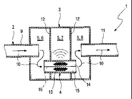
According to Fig. 1, a silencer 1 of an exhaust system 2
which is only shown here in the region of the silencer 1
which serves for discharging exhaust gases of an internal
combustion engine which is not shown here, which together
with the exhaust system 2 can be arranged in a motor
vehicle, a silencer housing 3 and at least one hollow body
4. The silencer housing 3 encloses a housing interior 5,
which for example can be divided into a plurality of
chambers 6, 7, 8. The hollow body 4 is arranged in the
housing interior 5 and serves for conducting exhaust gas.
For example and without restriction of the generality, an
inlet pipe 9 can be connected to the silencer housing 3,
through which exhaust gas according to the arrows 10 enters
the first chamber 6 of the housing interior 5 serving as
inlet chamber or deflection chamber and through the hollow
body 4 reaches into the third chamber 8 of the housing
interior 5 which serves as outlet chamber or deflection
chamber, from where the exhaust gas is discharged via an
outlet pipe 11. The hollow body 4 in the example is routed
through the second chamber 7 of the housing interior 5
serving as absorption chamber, which is separated from the
two other chambers 6, 8 through intermediate walls 12. The
hollow body 4 can be equipped permeable to airborne sound
in the region of the second chamber 7, for example by means
of a perforation 13.
The hollow body 4 is produced in half shell design, so that
it comprises two half shells 14, 15, which abut each other
in the region of a separating plane 16 and are fastened to
each other.
According to Fig. 2 to 4, the hollow body 4 can for example
be a Y-pipe. Alternatively, it can also be an X-pipe.
CA 02817806 2013-05-13
- 10 -
Alternatively, the hollow body 4 can also be a bent
deflection pipe or an unbent or straight pipe.
In Fig. 3 and 4, the perforation 13 introduced with
reference to Fig. 1 is also noticeable.
According to Fig. 2 to 8, the half shells 14, 15 are
fastened to each other with the help of fastening elements
17, 18, wherein these fastening elements 17, 18 are
directly formed on the half shells 14, 15. The fastening
elements 17, 18 in particular are integrally formed on the
respective half shell 14, 15. Preferentially, the two half
shells 14, 15 are fastened to each other exclusively via
these fastening elements 17, 18 directly formed thereon.
The half shells 14, 15 are for example formed sheet metal
parts which are each produced from one sheet metal piece
with the fastening elements 17, 18.
To realise these integrated fastening elements 17, 18, each
half shell 14, 15 comprises a collar 21 and 22 projecting
to the outside each in the region of the separating plane
16 on sides 19, 20 which are distant from each other,
namely on the one or first half shell 14 a first collar 21
each and a second collar 22 each on the other or second
half shell 15 each. On these collars 21, 22, the fastening
elements 17, 18 are formed. The mentioned sides 19, 20 are
practically distant from each other transversely to a flow
direction 23 of the hollow body 4 indicated by an arrow in
Fig. 2. The hollow body 4 thus comprises at least one
exhaust gas inlet 24 and at least one exhaust gas outlet
25. In the shown example of the hollow body 4 formed as a
Y-pipe, a single inlet opening 24 and exactly two outlet
openings 25 are obtained because of the flow direction 23
assumed here. An opposite flow direction is also
conceivable in principle. Furthermore, both the inlet
opening 24 as well as the two outlet openings 25 are each
arranged in planes in the example, which are perpendicular
CA 02817806 2013-05-13
- 11 -
to the separating plane 16. Practically, the separating
plane 16 divides the respective exhaust gas inlet 24 and
the respective exhaust gas outlet 25 by half.
On the previously mentioned collars 21, 22, the two half
shells 14, 15 abut each other, which is evident in
particular from Fig. 6 to 8. Furthermore, fastening the
half shells 14, 15 is effected via these collars 21, 22, so
that the collars 21, 22 are fastened to each other.
By means of Fig. 3 to 8, preferred embodiments for the
fastening elements 17, 18 are explained in more detail. It
is clear that in principle other fastening elements 17, 18
can also be employed which make possible mechanically
fixing the two half shells 14, 15, managing without
additional further fastening means such as for example
clamps, screws, welded connections in the process.
According to Fig. 3 to 8, the two collars 21 of the first
half shell 14 each comprise at least one strap 26. In the
shown preferred example, the respective collar 21 each
comprises two such straps 26, so that the first half shell
14 in the example comprises four such straps 26. The
respective strap 26 represents the respective fastening
element 17 of the first half shell 14, the respective strap
26 extends parallel to the separating plane 16 and spaced
from this in the longitudinal direction of the respective
collar 21 indicated by arrows 27.
According to Fig. 4, the second half shell 15 on its two
collars 22 comprises a collar portion 28 for each strap 26
of the first half shell 14, which represents a second
fastening element 18 that is complementary to the strap 26
or to the first fastening element 17. In the assembled
state, which is evident in Fig. 6c, 7 and 8, the respective
strap 26 engages over the associated collar portion 28.
CA 02817806 2013-05-13
- 12 -
In order for the respective strap 26 to be able to engage
over the associated collar portion 28, the respective
collar 22 of the second half shell 15 comprises for example
at least one interruption 29, which interrupts the
respective collar 22 in its collar longitudinal direction
27 and which is dimensioned so that the respective strap 26
can be passed through the respective interruption 29
perpendicularly to the separating plane 16 and thus
transversely to the longitudinal direction 27 of the
respective collar 21 and 22. The collars 22 of the
embodiment shown in Fig. 4 each show only one such
interruption 29, which one of the collar portions 28
respectively adjoins. The two other collar portions 28, by
contrast, are formed on a starting region 30 of the
respective collar 22 or - depending on orientation of the
longitudinal direction 27 - on an end region of the
respective collar 22. Thus, the associated strap 26 can
likewise be moved past the associated collar portion 28
perpendicularly to the separating plane 16.
Fig. 2 to 4 thus show embodiments, in which a plurality of
straps 26 is arranged on the same collar 21 in the
longitudinal direction 27 of the collar 21 spaced from one
another. In the example, for each collar 21 exactly two
straps 26 are spaced from each other in the collar
longitudinal direction 27. Furthermore, according to Fig. 3
and 4, the straps 26 are exclusively formed on the first
half shell 16, while the collar portions 28 associated with
the straps 26 are exclusively formed on the second half
shell 15 here.
The interruptions 29 can be easily realised through
punching out or cutting out corresponding portions of the
respective collar 22. By contrast, the straps 26 can be
realised for example in that within the respective collar
21 longitudinal portions are cut free or punched free and
CA 02817806 2013-05-13
- 13 -
subsequently opened out so that the straps 26 form integral
parts of the collars 21.
Fig. 5 shows the first half shell 14 in the region of such
a cut-free strap 26.
According to Fig. 6c, the respective strap 26 can be spaced
from the separating plane 16 so far that the associated
collar portion 28 can be clamped or clamped in with a
preload orientated perpendicularly to the separating plane
16. Together with the adhesive friction, a holding force
which is parallel to the separating plane 16 can be
generated in this way, which secures the half shells 14, 15
assembled to each other in the assembled state.
In order to increase this securing holding force, it can be
provided according to Fig. 7 and 8 to provide the
respective collar portion 28 with at least one protrusion
31 which projects perpendicularly to the separating plane
16 in the direction of the strap 26. In this way, the strap
26 when moving over the collar portion 28 is displaced by
the protrusion 31 in a direction directed away from the
separating plane 16, which increases the preload with which
the strap 26 is supported on the collar portion 28 or on
the protrusion 31 of the latter perpendicularly to the
separating plane 16. Such a protrusion 31 can for example
be integrally formed on the respective collar portion 28
with the help of a stamping operation.
According to Fig. 8, the respective strap 26 can be
equipped with an engagement profile 32 according to a
particularly advantageous embodiment, which is formed so
that it can engage with the respective protrusion 31, as
soon as the two half shells 14, 15 reach their assembly
position. For example, the engagement profile 32 projects
from the associated strap 26 in the direction of the
separating plane 16, as a result of which the engagement
CA 02817806 2013-05-13
- 14 -
profile 32 can engage behind the respective protrusion 31.
This creates a positive connection in a direction that is
parallel to the separating plane 16.
Additionally or alternatively to the respective protrusion
31 and/or to the respective engagement profile 32, at least
one insertion slope 35 can be provided, which in the
examples of Fig. 7 and 8 is formed on the respective free
end of the strap 26, in order to simplify fitting the
respective strap 26 onto the associated collar portion 28.
The assembly operation, through which the two half shells
14, 15 are fastened to each other in order to form the
hollow body 4, is explained in more detail in the following
by means of Fig. 6a to 6c.
According to Fig. 6a, the two half shells 14, 15 are
initially positioned relative to each other for adjusting a
starting position so that the respective strap 26 is
orientated perpendicularly to the separating plane 16 in
alignment with the associated interruption 29. The two half
shells 14, 15 are then moved towards each other according
to the arrows 33 perpendicularly to the separating plane
16. Here, the respective strap 26 can penetrate the
associated interruption 29 as a result of which the
intermediate position shown in Fig. 6b is reached. In this
intermediate position, the collars 21, 22 abut each other
in the separating plane 16. This first adjusting movement
according to the arrows 33 represents a fitting operation.
This fitting operation is now followed by a pushing
operation, during which the two half shells 14, 15 are
moved towards each other parallel to the separating plane
16 corresponding to the arrows 34, so that the respective
strap 26 can engage over the associated collar portion 28.
At the end of this pushing movement according to the arrows
34, the relative position according to Fig. 6c is obtained,
CA 02817806 2013-05-13
- 15 -
which represents an end position or a finish-assembled
state.