Note: Descriptions are shown in the official language in which they were submitted.
CA 02818029 2013-05-15
WO 2011/063498 PCT/CA2010/001564
FOOT STABILIZER SOCKS AND STABILIZER PADS THEREFOR
FIELD OF INVENTION
[0001] The present invention relates to stabilization of a human foot within a
piece of
footwear, and more particularly to socks and stabilizer pads for such
stabilization.
BACKGROUND OF THE INVENTION
[0002] The foot is the foundation on which the human body interacts with, and
distributes,
forces from the ground. It is a complex system made up of twenty-six bones,
thirty-three joints
and hundreds of muscles, tendons and ligaments. To function properly, all of
these complex
systems must work together, and a malfunction in any part of the foot may also
manifest itself
in other locations in the body.
[0003] Structurally, the foot has three main parts: the rearfoot, the midfoot
and the forefoot.
With reference now to Figures 1 to 4, an exemplary skeletal foot is shown
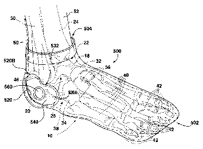
generally at 10, and
comprises rearfoot 12, midfoot 14, and forefoot 16. The skeletal structure of
the rearfoot 12
comprises two bones, namely the talus 18 and the calcaneous 20, as well as
three joints.
These three joints are the talocrural joint 22, between the upper portion of
the talus 18 and the
lower tibia 24, the subtalar joint 26, between the lower portion of the talus
18 and the upper
portion of the calcaneous 20, and the midtarsal joint, which, although
conventionally referred
to as a single joint, comprises the medial joints 28A between the talus 18 and
the navicular
bone 32, and the lateral joint 28B between the calcaneous 20 and the navicular
bone 32. The
midfoot 14 comprises five bones, namely the navicular bone 32, the cuboid bone
34 and three
cuneiform bones 36, and forms the arch 38 of the foot 10. The forefoot 16
comprises nineteen
bones, namely five metatarsal bones 40 and fourteen phalange bones 42. The
fibular
malleolus (also referred to as the lateral malleolus because of its position
on the lateral side of
the foot), which is a protrusion at the lower end of the fibula, is indicated
with the reference
numeral 46. Similarly, the tibial malleolus (also referred to as the medial
malleolus because of
its position on the medial side of the foot) is a protrusion at the lower end
of the tibia and is
indicated with the reference numeral 48.
- 1 -
CA 02818029 2013-05-15
WO 2011/063498 PCT/CA2010/001564
[0004] The movements of the foot 10 relative to the ankle are primarily
controlled by way of
the rearfoot 10. The primary movements of the talocrural joint 22 are plantar
flexion
(downward movement of the foot 10) and dorsiflexion (upward movement of the
foot 10).
These movements take place in the sagittal plane and are important for the
movement of the
foot and ankle. The movements supported by the subtalar joint 26 are complex;
the primary
movements enabled by the subtalar joint 26 are inversion (turning the bottom
or sole of the
foot 10 inward) and eversion (turning the bottom or sole of the foot outward).
The subtalar
joint 26 creates movements in all three cardinal planes and functions like a
mitred hinge. with
simultaneous motion in all three cardinal planes. As the subtalar joint 26
moves into eversion,
the tibia 24 rotates.
[0005] These four movements, plantar flexion, dorsiflexion, inversion and
eversion, along
with adduction (twisting the foot 10 inward) and abduction (twisting the foot
10 outward) are
involved with two main movements during the gait cycle (i.e. walking or
running), namely
pronation and supination. Pronation is the combination of dorsiflexion,
abduction and
eversion. Supination is the combination of plantar flexion, adduction and
inversion.
Supination and pronation are commonly used to define foot alignment under a
weight bearing
("closed-chain") condition. These motions are important to proper movement of
the foot 10
throughout the entire gait cycle.
[0006] The gait cycle can be divided into three main components. The first is
heel strike,
which is the period of time in which the calcaneous 20 (the heel) strikes the
ground (or other
surface) and the rest of the foot 10, i.e. the midfoot 14 and forefoot 16,
moves toward the
ground. The second stage is midstance, which is the point at which the bottom
of the entire
foot 10, that is, rearfoot 12, midfoot 14 and forefoot 16, is on the ground.
The third stage is
toe-off, which is the point at which the foot 10 is preparing to leave the
ground, and only the
bottom of the forefoot 16 remains in contact with the ground.
[0007] During heel strike the foot 10 is in a supinated position, which allows
the twenty-six
bones to be "locked" so that the foot 10 will have a stable base of support as
the calcaneous 20
hits the ground. As the gait cycle progresses to midstance, the foot 10
transitions from the
- 2 -
CA 02818029 2013-05-15
WO 2011/063498 PCT/CA2010/001564
"locked", supinated position to an "unlocked" pronated position, to allow the
foot 10 to
accommodate uneven surfaces. As the foot 10 transitions to toe-off, the foot
10 returns to the
supinated position to give the foot 10 a stable base of support to push off
the ground.
Throughout the gait cycle, the foot 10 is in constant motion allowing for both
stability and
flexibility.
[0008] The subtalar joint 26 (see Figure 1) plays an important role in the
foot 10, both
statically and dynamically, because of its central role in pronation and
supination, and also
because it can convert foot rotation into leg rotation and leg rotation into
foot rotation. The
subtalar joint 26 therefore has a direct role not only in the function of the
foot 10, but also the
knees, the hips and the pelvis, and an indirect role in respect of areas above
the pelvis
including the lower back.
SUMMARY OF THE INVENTION
[0009] In one aspect, the present invention is directed to a sock. The sock
has a foot section
having a shape corresponding to a human foot and comprising a rearfoot portion
corresponding to human calcaneous and talus bones and to tibial and fibular
malleoli, a
forefoot portion corresponding to human metatarsal and phalanx bones, and a
midfoot portion
between the rearfoot portion and the forefoot portion and corresponding to
human cuboid,
navicular and cuneiform bones. The sock has a medial stabilizer region on a
medial side of
the sock corresponding to a medial side of the foot and a lateral stabilizer
region on a lateral
side of the sock corresponding to a lateral side of the foot. In one
embodiment, the medial
stabilizer region and the lateral stabilizer region are separate and distinct
from one another.
The medial stabilizer region covers a forward medial region of the rearfoot
portion and a
rearward medial region of the midfoot portion, and the lateral stabilizer
region covers a
forward lateral region of the rearfoot portion.
[0010] In one embodiment, the medial stabilizer region extends from a position
on the
rearfoot portion corresponding to a position on the foot posterior to the
tibial malleolus and
anterior to the Achilles tendon, across a part of the rearfoot portion
corresponding to the lower
medial part of the talus and the upper medial part of the calcaneous, to
terminate at a position
-3 -
CA 02818029 2013-05-15
WO 2011/063498 PCT/CA2010/001564
on the midfoot portion corresponding to the navicular bone, and the lateral
stabilizer region
extends from a position on the rearfoot portion corresponding to a position on
the foot
posterior to the fibular malleolus and anterior to the Achilles tendon, across
a lower part of the
rearfoot portion corresponding to a lower lateral part of the talus and the
upper lateral part of
the calcaneous. The medial stabilizer region preferably includes a medial
malleolal concavity
at its upper edge to accommodate the tibial malleolus, and the lateral
stabilizer region
preferably includes a lateral malleolal concavity at its upper edge to
accommodate the fibular
malleolus.
[0011] In one embodiment, the lateral stabilizer region extends to and
terminates at a position
on the rearfoot portion corresponding to a position on the foot posterior and
proximal to the
cuboid bone.
[0012] In one embodiment, the sock includes a leg section corresponding at
least to the lower
portions of the human tibia and fibula bones. In such an embodiment, the
lateral stabilizer
region may extend from a position corresponding to a lateral position
posterior to the fibular
malleolus, anterior to the Achilles tendon, along an area of the leg section
corresponding to a
lower posterior part of the fibula, and the medial stabilizer region may
extend from a position
corresponding to a medial position posterior to the tibial malleolus, anterior
to the Achilles
tendon, along an area of the leg section corresponding to a lower posterior
part of the tibia.
[0013] Each of the medial stabilizer region and the lateral stabilizer region
may consist of a
pocket for receiving, respectively, a medial stabilizer pad and a lateral
stabilizer pad, or may
consist of a region over which is secured a textile selected from a group
consisting of hook-
surfaced textile and loop-surfaced textile. A medial stabilizer pad
corresponding in size and
shape to the medial stabilizer region may be secured to the sock at the medial
stabilizer region
and a lateral stabilizer pad corresponding in size and shape to the lateral
stabilizer region may
be secured to the sock at the lateral stabilizer region. The medial stabilizer
region and the
lateral stabilizer region may also comprise portions of the sock having
material that is
substantially thickened, relative to surrounding material, to form protrusions
that define the
medial stabilizer region and lateral stabilizer region.
- 4 -
CA 02818029 2013-05-15
WO 2011/063498 PCT/CA2010/001564
[0014] In another aspect, the present invention is directed to a stabilizer
pad for a human foot
that includes a rearfoot comprising calcaneous and talus bones and tibial and
fibular malleoli
and a midfoot comprising human cuboid, navicular and cuneiform bones. The
stabilizer pad
is shaped to, when positioned adjacent the medial part of the foot consisting
of the forward
medial region of the rearfoot and the rearward medial region of the midfoot,
extend from a
position on the foot posterior to the tibial malleolus and anterior to the
Achilles tendon, across
the lower medial part of the talus and the upper medial part of the calcaneous
to terminate at
the navicular bone. A malleolal concavity may be defined in the upper edge of
the stabilizer
pad to accommodate the tibial malleolus. The stabilizer pad may be formed from
a material
comprising silicone, or from foam, or may comprise a gel-filled enclosure.
[0015] In a further aspect, the present invention is directed to a stabilizer
pad for a human foot
that includes a rearfoot comprising calcaneous and talus bones and tibial and
fibular malleoli
and a midfoot comprising human cuboid, navicular and cuneiform bones. The
stabilizer pad
is shaped to, when positioned adjacent the forward lateral region of the
rearfoot, extend from a
position on the foot posterior to the fibular malleolus and anterior to the
Achilles tendon,
across a lower lateral part of the talus and an upper lateral part of the
calcaneous. A malleolal
concavity may be defined in the upper edge of the stabilizer pad to
accommodate the fibular
malleolus. The stabilizer pad may be formed from a material comprising
silicone, or from
foam, or may comprise a gel-filled enclosure.
[0016] In a still further aspect, the present invention is directed to a kit
for assembling a
stabilizer sock. The kit comprises at least one sock as described above, and a
plurality of
stabilizer pads of various thicknesses. Each stabilizer pad has a perimeter
shape matching a
perimeter shape of at least one of the medial stabilizer region and the
lateral stabilizer region
and is securable at the corresponding at least one of the medial stabilizer
region and the lateral
stabilizer region. The kit may further comprise instructions for selecting
stabilizer pads and
securing the selected stabilizer pads at the medial stabilizer region and the
lateral stabilizer
region.
- 5 -
CA 02818029 2013-05-15
WO 2011/063498 PCT/CA2010/001564
[0017] In yet a further aspect, the present invention is directed to a foot-
supporting sock
system. The foot-supporting sock system comprises a sock and two opposed
reniform pads
disposed on opposite sides of the sock. In one embodiment, the sock has a
closed toe end and
an open foot insertion end, and each reniform pad has a first end pointing
generally toward the
closed toe end of the sock and a second end pointing generally toward the open
foot insertion
end of the sock. The foot-supporting sock system may further comprise a set of
pockets
affixed to the sock, with each of the pockets enclosing a corresponding one of
the pads. In a
particular embodiment, each of the pockets includes an opening at a portion of
the pocket
opposite a surface of the sock to which the pocket is affixed, with each
opening permitting
removal of the respective enclosed pad.
[0018] In still yet a further aspect, the present invention is directed to a
foot-supporting sock
system comprising a sock and two opposed reniform pockets disposed on opposite
sides of the
sock. In one embodiment, the sock has a closed toe end and an open foot
insertion end, and
each reniform pocket has a first end pointing generally toward the closed toe
end of the sock
and a second end pointing generally toward the open foot insertion end of the
sock. The foot-
supporting sock system may further comprise a set of reniform pads each of
which is enclosed
in a corresponding one of the pockets. In a particular embodiment, each of the
pockets
includes an opening at a portion of the pocket opposite a surface of the sock
to which the
pocket is affixed, with each opening permitting removal of the respective
enclosed pad.
BRIEF DESCRIPTION OF THE DRAWINGS
[0019] These and other features of the invention will become more apparent
from the
following description in which reference is made to the appended drawings
wherein:
FIG.1 is a perspective view of a skeletal human right foot from the lateral
side thereof;
FIG. 2 is a lateral view of the human foot of Figure 1;
FIG. 3 is a medial view of the human foot of Figure 1;
FIG. 4 is a rear view of the human foot of Figure 1;
- 6 -
CA 02818029 2013-05-15
WO 2011/063498 PCT/CA2010/001564
FIG. 5 is a is a perspective view of a first exemplary embodiment of a foot
stabilizer sock,
according to an aspect of the present invention, with a human right foot
inside thereof
FIG. 6 is a lateral view of the foot stabilizer sock of Figure 5;
FIG. 7 is a medial view of the foot stabilizer sock of Figure 5;
FIG. 8 is a rear view of the foot stabilizer sock of Figure 5;
FIG. 9A is a cross-sectional view of an exemplary stabilizer region comprising
a pocket,
according to an aspect of the present invention;
FIG. 9B is a rear view of a first modified embodiment of the foot stabilizer
sock of Figure 5,
with a human right foot inside thereof;
FIG. 9C shows a first exemplary lateral stabilizer pad, positioned relative to
the lateral side of
a skeletal human right foot;
FIG. 9D shows a first exemplary medial stabilizer pad, positioned relative to
the medial side
of a skeletal human right foot;
FIG. 9E shows the lateral stabilizer pad of Figure 9C and the medial
stabilizer pad of Figure
9D, positioned relative to the rear of a skeletal human foot;
FIG. 9F is a rear view of a second modified embodiment of the foot stabilizer
sock of Figure
5, with a human right foot inside thereof
FIG. 10 is a is a perspective view of a second exemplary embodiment of a foot
stabilizer sock,
according to an aspect of the present invention; with a human right foot
inside thereof
FIG. 11 is a lateral view of the foot stabilizer sock of Figure 10;
FIG. 12 is a medial view of the foot stabilizer sock of Figure 10;
- 7 -
CA 02818029 2013-05-15
WO 2011/063498 PCT/CA2010/001564
FIG. 13 is a is a perspective view of a third exemplary embodiment of a foot
stabilizer sock,
according to an aspect of the present invention; with a human right foot
inside thereof
FIG. 14 is a lateral view of the foot stabilizer sock of Figure 13;
FIG. 15 is a medial view of the foot stabilizer sock of Figure 13;
FIG. 16A shows a second exemplary lateral stabilizer pad, positioned relative
to the lateral
side of a skeletal human right foot;
FIG. 16B shows a second exemplary medial stabilizer pad, positioned relative
to the medial
side of a skeletal human right foot;
FIG. 16C shows the lateral stabilizer pad of Figure 16A and the medial
stabilizer pad of
Figure 16B, positioned relative to the rear of a skeletal human foot;
FIG. 17 shows a first exemplary kit, according to an aspect of the present
invention;
FIG. 18 shows a second exemplary kit, according to an aspect of the present
invention;
FIG. 19A shows construction of an exemplary stabilizer pad, according to an
aspect of the
present invention;
FIG. 19B is a cross-sectional view taken along the line 19B-19B in Figure 19A;
FIG. 20 is a side view of an exemplary running sock according to an aspect of
the present
invention;
FIG. 21 is a side view of an exemplary skating sock according to an aspect of
the present
invention;
FIG. 22 is a side view of an exemplary skiing sock according to an aspect of
the present
invention;
- 8 -
CA 02818029 2013-05-15
WO 2011/063498 PCT/CA2010/001564
FIG. 23A is a table showing exemplary dimensions for a stabilizer pad for
skiing and hockey
socks according to an aspect of the present invention;
FIGS. 23B to 23D are top, side and perspective views of a stabilizer pad for
ski and hockey
socks according to an aspect of the present invention, corresponding to the
dimensions shown
in the table of FIG. 23A;
FIG. 24A is a table showing exemplary dimensions for a stabilizer pad for
running socks
according to an aspect of the present invention;
FIGS. 24B to 24D are top, side and perspective views of a stabilizer pad for
running socks
according to an aspect of the present invention, corresponding to the
dimensions shown in the
table of FIG. 24A;
FIGS. 25A to 25C are top, side and perspective views of a left side boot bang
protector pad,
according to an aspect of the present invention;
FIG. 25D shows a table containing exemplary dimensions for the boot bang
protector pad of
FIGS. 25A to 25C;
FIGS. 26A to 26C are top, side and perspective views of a right side boot bang
protector pad,
according to an aspect of the present invention;
FIG. 26D shows a table containing exemplary dimensions for the boot bang
protector pad of
FIGS. 26A to 26C;
FIGS. 27A to 25D are top, side, perspective and end views of a lace bite
protector pad,
according to an aspect of the present invention;
FIG. 27E shows a table containing exemplary dimensions for the lace bite
protector pad of
FIGS. 27A to 27D;
FIG. 28A is a schematic side view of an exemplary running sock according to an
aspect of the
present invention, showing various dimensions thereof;
- 9 -
CA 02818029 2013-05-15
WO 2011/063498 PCT/CA2010/001564
FIG. 28B shows two tables containing exemplary dimensions of the running sock
of Figure
28A;
FIG. 29A is a schematic side view of an exemplary hockey sock according to an
aspect of the
present invention, showing various dimensions thereof
FIG. 29B shows two tables containing exemplary dimensions of the hockey sock
of Figure
29A;
FIG. 30A is a schematic side view of an exemplary skiing sock according to an
aspect of the
present invention, showing various dimensions thereof;
FIG. 30B shows two tables containing exemplary dimensions of the skiing sock
of Figure
30A;
FIG. 31A is a schematic view of an exemplary stabilizer pad pocket for a
running socks
according to an aspect of the present invention, showing various dimensions
thereof
FIG. 31B shows a table containing exemplary dimensions of the stabilizer pad
pocket of
Figure 31A;
FIG. 32A is a schematic view of an exemplary stabilizer pad pocket for hockey
and skiing
socks according to an aspect of the present invention, showing various
dimensions thereof
FIG. 32B shows a table containing exemplary dimensions of the stabilizer pad
pocket of
Figure 32A;
FIG. 33A is a schematic view of an exemplary boot bang protector pad pocket
for skiing socks
according to an aspect of the present invention, showing various dimensions
thereof
FIG. 33B shows a table containing exemplary dimensions of the boot bang
protector pad
pocket of Figure 33A;
-10-
CA 02818029 2013-05-15
WO 2011/063498 PCT/CA2010/001564
FIG. 34A is a schematic view of an exemplary lace bite protector pad pocket
for hockey socks
according to an aspect of the present invention, showing various dimensions
thereof; and
FIG. 34B shows a table containing exemplary dimensions of the lace bite
protector pad pocket
of Figure 34A.
DETAILED DESCRIPTION
[0020] As will be described in greater detail below, according to an aspect of
the invention
foot stabilizer socks may be provided with stabilizer pads that are carefully
anatomically
positioned to improve the interface between the user's foot and lower leg and
a piece of outer
footwear, such as a shoe, boot, skate, or the like.
[0021] As can be seen best by reference to Figure 4, the skeletal structure of
a human foot
results in certain recessed portions of a the foot, such as the regions 46A,
48A immediately
below the fibular malleolus 46 and the tibial malleolus 48, respectively.
Because the shape of
outer footwear is generally constrained by the outer boundaries of the foot
10, the recessed
regions 46A, 48A may result in gaps between the foot and the outer footwear,
where the foot
is unsupported. This situation is undesirable, as it reduces the stability of
the interface
between the foot 10 and the outer footwear.
[0022] With reference now to Figures 5 to 8, a first exemplary foot stabilizer
sock is shown
generally at 500. The first foot stabilizer sock 500 includes a foot section
denoted generally at
510 which has a shape corresponding to a human foot, and has a closed toe end
502 and an
open foot insertion end 504. A human lower leg 52, including a human foot
whose skeleton
is shown in dotted lines, is shown inside the sock 500, to show relative
positioning of
portions of the first foot stabilizer sock 500; it is understood that a human
foot of course forms
no part of the present invention.
[0023] As shown in Figures 6 and 7, the foot section 510 comprises a rearfoot
portion 510A, a
midfoot portion 510B, and a forefoot portion 510C. The rearfoot portion 510A
corresponds in
position to the human calcaneous 20 and talus 18 and to the fibular and tibial
malleoli 46, 48,
respectively. The midfoot portion 510B corresponds in position to human
navicular, cuboid
- 11 -
CA 02818029 2013-05-15
WO 2011/063498 PCT/CA2010/001564
and cuneiform bones 32, 34, 36, respectively, and the forefoot portion 510C
corresponds to
human metatarsal and phalanx bones 40, 42, respectively. The midfoot portion
510B is
positioned between the rearfoot portion 510A and the forefoot portion 510C.
[0024] The first foot stabilizer sock 500 has a generally reniform lateral
stabilizer region 520
on a lateral side of the foot stabilizer sock 500, corresponding to the
lateral side of the foot 10,
and a generally reniform medial stabilizer region 524 on a medial side of the
foot stabilizer
sock 500, corresponding to the medial side of the foot 10. In the illustrated
embodiment, the
lateral stabilizer region 520 and the medial stabilizer region 524 are
separate and distinct from
one another. The medial stabilizer region 524 has a first end 524A pointing
generally towards
the closed toe end 502 of the foot stabilizer sock 500, and a second end 524B
pointing
generally toward the open foot-insertion end of the foot stabilizer sock 500.
Similarly, the
lateral stabilizer region 520 has a first end 520A pointing generally towards
the closed toe end
502 of the foot stabilizer sock 500, and a second end 520B pointing toward the
open foot-
insertion end 504 of the foot stabilizer sock 500.
[0025] As can best be seen in Figure 6, the lateral stabilizer region 520
covers a forward
lateral region of the rearfoot portion 510A, and as shown in Figure 7, the
medial stabilizer
region 524 covers a forward medial region of the rearfoot portion 510A and a
rearward media
region of the midfoot portion 510B.
[0026] The lateral stabilizer region 520 extends from a position on the
rearfoot portion 510A
corresponding to a position on the human foot 10 that is posterior to the
fibular malleolus 46
and anterior to the Achilles tendon 50, across a lower part of the rearfoot
portion 510A
corresponding to a lower lateral part of the talus 18 and an upper lateral
part of the calcaneous
20. The medial stabilizer region 524 extends from a position on the rearfoot
portion 510A
corresponding to a position on the human foot 10 that is posterior to the
tibial malleolus 48
and anterior to the Achilles tendon 50, across a part of the rearfoot portion
510A
corresponding to a lower medial part of the talus 18 and an upper medial part
of the
calcaneous 20, to terminate at a position on the midfoot portion 510B
corresponding to the
navicular bone 32. In the illustrated embodiment, the medial stabilizer region
524 includes a
- 12 -
CA 02818029 2013-05-15
WO 2011/063498 PCT/CA2010/001564
medial malleolal concavity 530 at its upper edge to accommodate the tibial
malleolus 48, and
the lateral stabilizer region 520 includes a lateral malleolal concavity 532
at its upper edge to
accommodate the fibular malleolus 46. The lateral stabilizer region 520
extends to and
terminates at a position on the rearfoot portion 510A corresponding to a
position on the
human foot 10 that is posterior and proximal to the cuboid bone 34.
[0027] In the particular illustrated embodiment shown in Figures 5 to 8, the
medial stabilizer
region 524 and the lateral stabilizer region 520 each consist of a pocket 544,
540, respectively,
secured to the sock 500 for receiving, respectively, a generally reniform
medial stabilizer pad
and a generally reniform lateral stabilizer pad so that each pad is enclosed
in a corresponding
one of the pockets. In the illustrated embodiment, the pads are inserted into,
and can be
removed from, the pockets 540, 544 by way of respective stretchable circular
apertures 560,
564 located at a portion of the respective pocket 540, 544 opposite a surface
of the sock 500 to
which the pocket 540, 544 is affixed. Thus, there is provided a foot-
supporting sock system
comprising the foot stabilizer sock 500 and the two opposed reniform pockets
544, 540
disposed on opposite sides of the sock 500.
[0028] As shown in Figure 9A, the pockets 540, 544 are formed by securing an
outer layer
910 made from stretchable material to the underlying material 912 of the sock
500, to define a
cavity 914 for receiving a pad (not shown in Figure 9A). The outer layer 910
can be secured
to the underlying material 912 of the sock 500 by any suitable technique,
including without
limitation stitching, heat sealing, RF or infrared welding, and adhesive. The
outer layer 910
includes an aperture 916 having a reinforced edge or edges 918, through which
a pad (not
shown in Figure 9A) can be inserted into the cavity 914. Because the outer
layer 910 is made
from stretchable material, the aperture 916 can be stretched to permit
insertion of the pad,
after which the aperture 916 will return to its nominal size so that the pad
will be retained in
the cavity 914. Thus, a medial stabilizer pad 924 (see Figure 9C),
corresponding in size and
shape to the medial stabilizer region, may be removably secured to the sock
500 at the medial
stabilizer region 524, and a lateral stabilizer pad 920 (see Figure 9B),
corresponding in size
and shape to the lateral stabilizer region 520, may be removably secured to
the sock 500 at the
lateral stabilizer region, in each case by insertion into the appropriate
pocket.
- 13 -
CA 02818029 2013-05-15
WO 2011/063498 PCT/CA2010/001564
[0029] Alternatively, as shown in Figure 9B, the medial stabilizer region and
the lateral
stabilizer region may each consist of a region 940, 942, respectively, over
which is secured a
textile 944 selected from a group consisting of hook-surfaced textile and loop-
surfaced textile.
Correspondingly shaped medial and lateral stabilizer pads 946, 948, having
complementary
textile 950 (i.e. hook-surfaced if the textile 944 is loop-surfaced, and loop-
surfaced if the
textile 944 is hook surfaced) on one side thereof may be removably secured to
the medial
stabilizer region 940 and the lateral stabilizer region 942 by interaction
between the hook
surfaces and the loop surfaces.
[0030] Exemplary stabilizer pads for use with a stabilizer sock according to
an aspect of the
present invention, such as the first stabilizer sock 500, are shown in Figures
9C, 9D and 9E. It
will be understood that the stabilizer pads may come in different sizes, so
that an appropriate
size of pad may be selected for the size of the foot with which it is to be
used. For example,
there could be two different sizes of stabilizer pad (small and large), three
sizes (small,
medium and large), and so on, or a "one-size fits all" approach may be used.
In addition,
stabilizer pads may have sizes across multiple dimensions, so that different
stabilizer pads
may have different thicknesses while having a constant outer perimeter size.
In an exemplary
implementation, where pockets are used for the stabilizer regions, there may
be, for each of
the lateral and medial sides, a first pocket perimeter size for socks in the
extra small, small,
and medium sizes, and a second pocket size for socks in the large and extra
large size. Each
pocket could then accommodate stabilizer pads of varying thicknesses.
[0031] Reference is now made to Figure 9C, where a generally reniform lateral
stabilizer pad
for a human foot is indicated by the reference numeral 920. The lateral
stabilizer pad 920 is
shaped to, when positioned adjacent a forward lateral region of the rearfoot
of a
correspondingly sized human foot (e.g. by insertion into the correspondingly
shaped pocket
defining a lateral stabilizer region 520, as shown in Figure 6), extend from a
position on the
foot posterior to the fibular malleolus 46 and anterior to the Achilles tendon
50, curve around
the fibular malleolus 46, and extend across a lower lateral part of the talus
18 and an upper
lateral part of the calcaneous 20, with a lateral malleolal concavity 932
defined in an upper
edge of the lateral stabilizer pad 920 to accommodate the fibular malleolus
46.
-14-
CA 02818029 2013-05-15
WO 2011/063498 PCT/CA2010/001564
[0032] Referring now to Figure 9D, a generally reniform medial stabilizer pad
for a human
foot is shown generally at 924. The medial stabilizer pad 924 is shaped to,
when positioned
adjacent a medial part of the foot consisting of a forward medial region of
the rearfoot and a
rearward medial region of the midfoot (e.g. by insertion into the
correspondingly shaped
pocket defining a medial stabilizer region 524, as shown in Figure 7), extend
from a position
on the foot posterior to the tibial malleolus 48 and anterior to the Achilles
tendon 50, curve
around the tibial malleolus 48, and extend across a lower medial part of the
talus 18 and an
upper medial part of the calcaneous 20 to terminate at the proximal aspect of
the navicular
bone 32, with a medial malleolal concavity 930 defined in an upper edge of the
medial
stabilizer pad 924 to accommodate the tibial malleolus 48.
[0033] Figure 9E is a rear view of a skeletal human foot, showing the
positioning of the
medial stabilizer pad 924 and the lateral stabilizer pad 920 relative to the
bones therein.
[0034] In addition, as shown in Figure 9F, the medial stabilizer region and
lateral stabilizer
region may comprise portions of the sock having material that is substantially
thickened,
relative to the surrounding material, to form protrusions 994, 990 that define
the medial
stabilizer region and lateral stabilizer region.
[0035] The first foot stabilizer sock 500 shown in Figures 5 to 8, and the
pads 920, 924, are
intended for use with a low-top running shoe (not shown); hence the foot
stabilizer sock 500
may be considered a running sock 500. Other embodiments of stabilizer socks
for use with
other types of footwear are now described.
[0036] Referring now to Figure 10, a second exemplary foot stabilizer sock
1000 is shown on
a human lower leg 52 including a foot 10. The second foot stabilizer sock 1000
is similar to
the first foot stabilizer sock 500 shown in Figures 5 to 8, and as such
corresponding reference
numerals are used to refer to corresponding features, except beginning with
the number "10"
instead of "5". While the first foot stabilizer sock 500 ended at the ankle,
the second foot
stabilizer sock 1000 also includes a leg section 1012 extending from the foot
section 1010 and
corresponding at least to the lower portions of the tibia 24 and fibula 30,
and terminating at an
- 15 -
CA 02818029 2013-05-15
WO 2011/063498 PCT/CA2010/001564
open foot-insertion end 1004. As such, the second foot stabilizer sock 1000 is
suitable for use
with shoes or boots that include an ankle portion, such as hiking, tactical or
combat boots, or
high-top athletic shoes. The foot stabilizer sock may be particularly
advantageously used with
skates, such as ice skates or in-line wheeled skates.
[0037] With shoes or boots having an ankle portion, in addition to the
recessed regions 46A,
48A immediately below the fibular malleolus 46 and the tibial malleolus 48,
respectively,
there can also be additional gaps between the human ankle and the ankle
portion of the
footwear in the area adjacent the lower posterior part of the fibula 30,
posterior to the fibular
malleolus 46 and anterior to the Achilles tendon 50, and in the area adjacent
the lower
posterior part of the tibia 24, posterior to the tibial malleolus 48 and
anterior to the Achilles
tendon 50.
[0038] Accordingly, in the second foot stabilizer sock 1000, as best seen in
Figure 12 the
medial stabilizer region 1024 has an elongate generally reniform shape, and
extends
downwardly from a position on the rearfoot portion 1010A corresponding to a
medial position
on the foot 10 posterior to the tibia 24, anterior to the Achilles tendon 50,
along an area of the
leg section 1012 corresponding to a lower posterior part of the tibia 24,
curving beneath the
tibial malleolus 48 to define the medial malleolal concavity 1030, and then
extending
forwardly across a part of the rearfoot portion 1010A corresponding to a lower
medial part of
the talus 18 and an upper medial part of the calcaneous 20, to terminate at a
position on the
midfoot portion 1010B corresponding to the navicular bone 32. Similarly, in
the second foot
stabilizer sock 1000, as best seen in Figure 11 the lateral stabilizer region
1020 has an
elongate generally reniform shape, and extends downwardly from a position on
the rearfoot
portion 1010A corresponding to a lateral position on the foot 10 posterior to
the fibula 30,
anterior to the Achilles tendon, along an area of the leg section 1012
corresponding to a lower
posterior part of the fibula 30, curving beneath the fibular malleolus 48 to
define the fibular
malleolal concavity 1032, and extending forwardly across a lower part of the
rearfoot portion
1010A corresponding to a lower lateral part of the talus 18 and an upper
lateral part of the
calcaneous 20. As with the first foot stabilizer sock 500, the medial
stabilizer region 1024 has
a first end 1024A pointing generally towards the closed toe end 1002 of the
foot stabilizer
-16-
CA 02818029 2013-05-15
WO 2011/063498 PCT/CA2010/001564
sock 1000, and a second end 1024B pointing generally toward the open foot-
insertion end of
the foot stabilizer sock 1000, and the lateral stabilizer region 1020 has a
first end 1020A
pointing generally towards the closed toe end 1002 of the foot stabilizer sock
1000, and a
second end 1020B pointing toward the open foot-insertion end of the foot
stabilizer sock
1000.
[0039] The second foot stabilizer sock 1000 also includes a lace bite
protector region 1070
extending along the front surface of the sock 1000 from the posterior upper
surface of the foot
portion 1010 to the lower anterior surface of the leg portion 1012. More
particularly, the lace
bite protector region= 1070 extends from a position on the forefoot portion
1010C
corresponding to the posterior ends of the inner metatarsal bones 40, across
the upper part of
the midfoot portion 1010B corresponding to at least the inner cuneiform bones
36 and the
navicular bone 32, and then upwardly along the lower front of the leg section
1012,
corresponding to the lower front of the tibia 24 and fibula 30. In the
illustrated embodiment,
the lace bite protector region 1070 comprises a pocket 1072 having a
stretchable aperture
1074 permitting a suitable pad 1076 to be inserted into the pocket 1072 to
provide cushioning
so as to prevent tight laces on a piece of footwear, such as an ice skate or
in-line wheeled
skate, from biting into a user's foot, and also to increase stability by
providing an interface
between the top of the foot 10 and the lace portion of the footwear. An
exemplary lace bite
protector pad will be described in greater detail below.
[0040] Reference is now made to Figures 13 to 15, where a third embodiment of
a foot
stabilizer sock 1300 is shown on a human lower leg 52, including the foot 10.
The third foot
stabilizer sock 1300 is similar to the second foot stabilizer sock 1000 shown
in Figures 10 to
12, and as such corresponding reference numerals are used to refer to
corresponding features,
except beginning with the number "13" instead of "10". Like the second foot
stabilizer sock
1000, the third foot stabilizer sock 1300 includes a leg section 1312
extending from the foot
section 1310 and corresponding at least to the lower portions of the tibia 24
and fibula 30 and
is therefore suitable for use with shoes or boots that include an ankle
portion. The lateral
stabilizer region 1320 and the medial stabilizer region 1324 of the third
embodiment of the
stabilizer sock 1300 have the same shape, position and orientation on the sock
1300 as do the
- 17 -
CA 02818029 2013-05-15
WO 2011/063498 PCT/CA2010/001564
lateral stabilizer region 1020 and the medial stabilizer region 1024 of the
second embodiment
of the stabilizer 1000.
[0041] The third embodiment of the stabilizer sock 1300 includes a boot bang
protector
region 1380 positioned on the leg section 1312 of the stabilizer sock 1300. In
certain
sporting activities where the user wears boots constructed of hard plastic,
such as skiing, the
user's shins, and in particular the anterior margin of the tibia 24, can
collide with the inside of
the boot, potentially causing injury. The boot bang protector region 1380 is
positioned to
cushion the user's legs against such impact. In the illustrated embodiment,
the boot bang
protector region 1380 comprises a pocket 1382 having a stretchable aperture
1384 permitting
a suitable pad 1386 to be inserted into the pocket 1382 to provide cushioning.
An exemplary
boot bang protector pad will be described in greater detail below.
[0042] Figures 16A and 16B show stabilizer pads for use with the second and
third
embodiments 1000, 1300 of stabilizer socks according to aspects of the present
invention. In
particular, Figure 16A shows a lateral stabilizer pad 1620, and Figure 16B
shows a medial
stabilizer pad 1624.
[0043] Referring to Figure 16A, the lateral stabilizer pad 1620 is shaped to,
when positioned
adjacent a forward lateral region of the rearfoot of a correspondingly sized
human foot (e.g. by
insertion into the pocket defining a lateral stabilizer region 1020, 1320 as
shown in Figures 11
and 14, respectively) extend downwardly from a lateral position posterior to
the fibula 30,
anterior to the Achilles tendon, along the lower posterior part of the fibula
30, curving beneath
the fibular malleolus 48 to define the fibular malleolal concavity 1032, and
extending
forwardly across a lower part of the rearfoot portion 1010A corresponding to a
lower lateral
part of the talus 18 and an upper lateral part of the calcaneous 20.
[0044] Now referring to Figure 16B, the medial stabilizer pad 1624 is shaped
to, when
positioned adjacent a forward medial region of the rearfoot of a
correspondingly sized human
foot (e.g. by insertion into the pocket defining a medial stabilizer region
1024, 1324 as shown
in Figures 12 and 15, respectively), extend downwardly from a medial position
posterior to
- 18 -
CA 02818029 2013-05-15
WO 2011/063498 PCT/CA2010/001564
the tibia 24, anterior to the Achilles tendon 50, along the lower posterior
part of the tibia 24,
curving beneath the tibial malleolus 48 to define the medial malleolal
concavity 1630, and
then extend forwardly across a lower part of the rearfoot portion 1010A and
midfoot portion
1010B corresponding to the lower medial part of the talus 18 and the upper
medial part of the
calcaneous 20, to terminate at the proximal aspect of the navicular bone 32.
[0045] Figure 16C is a rear view of a skeletal human foot, showing the
positioning of the
medial stabilizer pad 1624 and the lateral stabilizer pad 1620.
[0046] While the medial stabilizer regions 1024, 1324, lateral stabilizer
regions 1020, 1620,
lace bite protector region 1070 and boot bang protector region 1380 have been
depicted in
Figures 10 to 12 and 13 to 16 as pockets, it will be appreciated that these
regions may also be
formed by one of hook or loop attachment fabric, or by thickened material of
the sock
defining protrusions, as described above.
[0047] As a matter of brevity, only right foot socks have been illustrated in
detail in the
above-described figures; it will be appreciated that left foot socks according
to aspects of the
present invention will be substantially identical to right foot socks, but
arranged as a mirror
image thereof.
[0048] Figures 9C and 9D and Figures 16B and 16C show embodiments of lateral
stabilizer
pads 920, 1620 and medial stabilizer pads 924, 1624, respectively, which are
preferred from
an anatomical perspective. Specifically, it will be observed that the medial
stabilizer pads
924, 1624 have a more elongate lower portion (i.e. extend further toward the
toes when
properly positioned) than the lateral stabilizer pads 920, 1620. This
difference in shape is also
reflected in the medial stabilizer regions 524, 994, 1024, 1324 and the
lateral stabilizer regions
520, 990, 1020, 1320. While this difference in shape is preferable from an
anatomical
perspective, it is presently preferred, from a manufacturing simplification
perspective, to use
identically shaped pads as both medial stabilizer pads and lateral stabilizer
pads. Although
this approach is less preferred from an anatomical perspective, it is still
sufficient from an
-19-
CA 02818029 2013-05-15
WO 2011/063498 PCT/CA2010/001564
anatomical perspective and has the benefit of reducing the number of different
types of
stabilizer pads that must be manufactured.
[0049] Aspects of the present invention also provide for a kit for assembling
a stabilizer sock.
Such a kit would include at least one sock, and preferably two socks, which
include a medial
stabilizer region and a lateral stabilizer region as described herein, such as
the socks 500, 1000
1300. A kit including two socks will preferably include one right foot sock
and one left foot
sock.
[0050] As will be appreciated, different sizes of foot stabilizer socks
according to aspects of
the present invention may be used for different sizes of feet. In addition to
the socks, a kit
according to an aspect of the present invention would also include a plurality
of stabilizer
pads, such as the pads 920, 924, 1620, 1624, of various thicknesses. The pads
are provided in
various thicknesses to allow a user to select a pad having the thickness best
suited to the user's
foot and the outer footwear with which the sock will be worn. Each stabilizer
pad in the kit
will have a perimeter shape matching a perimeter shape of at least one of the
medial stabilizer
region and the lateral stabilizer region and will be securable at the
corresponding medial
stabilizer region and/or lateral stabilizer region, for example by insertion
into a pocket. In one
embodiment, differently shaped medial stabilizer pads and lateral stabilizer
pads are provided.
In such an embodiment, each medial stabilizer pad has a perimeter shape
matching the
perimeter shape of the corresponding medial stabilizer region, and each
lateral stabilizer pad
has a perimeter shape matching the perimeter shape of the corresponding
lateral stabilizer
region. In another embodiment, the kit includes pads of a single general
shape, which may be
used as both medial and lateral stabilizer pads.
[0051] Such a kit would also include instructions for selecting at least one
of the medial
stabilizer pads and securing each selected one of the medial stabilizer pads
at a corresponding
medial stabilizer region, and for selecting at least one of the lateral
stabilizer pads and
securing each selected one of the lateral stabilizer pads to a corresponding
lateral stabilizer
region. For example, the instructions may provide for the installation of two
medial or lateral
- 20 -
CA 02818029 2013-05-15
WO 2011/063498 PCT/CA2010/001564
stabilizer pads inside a single pocket, to provide thicker padding than a
single pad. The
instructions can optionally form part of the packaging in which the kit is
sold.
[0052] With reference now to Figure 17, an exemplary kit is shown generally at
1710. The kit
1710 includes two socks 1700 similar in construction to the sock 500, each
having a medial
stabilizer region 1720A and a lateral stabilizer region 1724A, and also
includes a plurality of
correspondingly shaped medial stabilizer pads 1720B and lateral stabilizer
pads 1724B,
similar to the medial and lateral stabilizer pads 920 and 924, respectively.
The kit 1710 also
includes a set of instructions 1790 for selecting and securing the medial
stabilizer pads 1720B
and lateral stabilizer pads 1724B. Similarly, Figure 18 depicts an exemplary
kit 1810. The kit
1710 includes two socks 1800, each having a medial stabilizer region 1820A and
a lateral
stabilizer region 1824A, and also includes a plurality of correspondingly
shaped medial
stabilizer pads 1720B and lateral stabilizer pads 1724B, similar to the medial
and lateral
stabilizer pads 1620 and 1624, respectively. In addition, the socks 1810 may
include lace bite
protector regions 1870A, similar to the lace bite protector region 1070A, or
boot bang
protector regions 1880A similar to the boot bang protector region 1380, or
both, and the kit
1810 includes a plurality of lace bite protector pads 1870B of different
thicknesses, a plurality
of boot bang protector pads 1880B of different thicknesses, or both. Like the
kit 1710, the kit
1810 also includes a set of instructions 1890 for selecting and securing the
medial stabilizer
pads 1820B and lateral stabilizer pads 1824B.
[0053] Lateral stabilizer pads such as the pads 520, 920, 1620 and medial
stabilizer pads such
as the pads 524, 924, 1624 may be formed from a variety of suitable materials.
For example,
the pads 920, 924 may be formed from a material comprising silicone, from foam
(such as
memory foam), or the pads 920, 924 may comprise a gel or a gel-filled
enclosure. Figures
19A and 19B show an exemplary pad 1910 formed from a suitable gel material.
The pad
1910 has a plurality of apertures 1912 defined therethrough to improve
breathability, and may
optionally be disposed within a covering of breathable fabric 1914.
[0054] Foot stabilizer socks, such as the socks 500, 1000 and 1300, may, in
addition to the
inventive lateral and medial stabilizer regions and pads, include thickened
fabric or other
-21 -
CA 02818029 2013-05-15
WO 2011/063498 PCT/CA2010/001564
material to provide cushioning and durability at the rearfoot and forefoot,
arch support at the
midfoot, and fabric with increased breathability on the upper surface of the
foot section. Foot
stabilizer socks according to an aspect of the present invention may be made
from fabric
comprising a suitable Nylon/polyester/spandex blend, such as 77% Nylon, 20%
polyester and
3% spandex.
[0055] With reference now to Figure 20, an exemplary construction of a running
sock for use
with a running shoe is shown generally at 2000 and comprises a foot section
2010. The
exemplary running sock 2000 includes both lateral and medial stabilizer
regions as described
above; only the lateral stabilizer region 2020 is shown in Figure 20, taking
the form of a
pocket as described above. Positioning of the lateral and medial stabilizer
regions is as
described above in respect of Figures 5 to 8, and is also described in greater
detail below.
The exemplary running sock 2000 comprises a cuff part 2001, a toe ventilation
part 2002, a
fitting band 2003, a foot bottom part 2004 and a foot top part 2005. The cuff
part 2001 is
made from a 2x1 rib knit, folded over for double thickness, the toe
ventilation part 2002 is
made from a 1 xl mesh knit, the fitting band 2003 is made from a 2x1 rib knit,
the foot bottom
part 2004 is made from a cushion knit or terry knit and the foot top part 2005
is made from a
flat knit.
[0056] Reference is now made to Figure 21, where an exemplary construction of
a skating
sock for use with a skate (e.g. an ice skate or in-line wheeled skate) is
shown generally at
2100 and includes a foot section 2110 and a leg section 2112. Like the
exemplary running
sock 2000, the exemplary skating sock 2100 includes both lateral and medial
stabilizer
regions (only the lateral stabilizer region 2120, in the form of a pocket, is
shown in Figure 21).
The exemplary skating sock 2100 also includes a lace bite protector pocket
2170. Positioning
of the lateral and medial stabilizer regions is as described above in respect
of Figures 10 to 12
and 16A to 16C and is also described further below. The exemplary hockey sock
2100
comprises a cuff part 2101, a toe ventilation part 2102, a fitting band 2103,
a foot bottom part
2104, a foot top part 2105 and a leg part 2107. The cuff part 2101 is made
from a 2x1 rib
knit, folded over for double thickness, the toe ventilation part 2102 is made
from a lx1 mesh
knit, the fitting band 2103 is made from a 2x1 rib knit, the foot bottom part
2104 is made from
- 22 -
CA 02818029 2013-05-15
WO 2011/063498 PCT/CA2010/001564
a cushion knit or terry knit and the foot top part 2105 and leg part 2107 are
made from a flat
knit.
[0057] Figure 22 shows an exemplary skiing sock 2200 for use with a ski boot.
The skiing
sock 2200 and includes a foot section 2110 and a leg section 2112. Like the
exemplary socks
2000 and 2100 described above, the exemplary skiing sock 2200 includes both
lateral and
medial stabilizer regions in the form of pockets (only the lateral stabilizer
region 2220 being
shown). Similarly to the exemplary hockey sock 2100, the exemplary skiing sock
2200
comprises a cuff part 2201 made from a 2x1 rib knit, folded over for double
thickness, a toe
ventilation part 2202 made from a lx1 mesh knit, a fitting band 2203 made from
a 2x1 rib
knit, a foot bottom part 2204 made from a cushion knit or terry knit, and a
foot top part 2205
and leg part 2207 made from a flat knit. Optionally, for increased warmth
certain portions of
the skiing sock 200, such as the leg part 2207 and the portion of the foot
bottom part 2204
immediately forward of the fitting band 2203 and below the toe ventilation
part 2202, may be
made from wool or a wool blend.
[0058] As noted above, stabilizer pads and socks according to aspects of the
present invention
may be provided in a variety of sizes. In a presently preferred embodiment,
medial and lateral
stabilizer pads, boot bang protector pads and lace bite protector pads are
provided in medium
(M), large (L), and extra-large (XL) sizes, with each size being provided in
three different
thicknesses, for a total of nine different sizes.
[0059] Figures 23B to 23D show, respectively, a front, side and perspective
view of an
exemplary stabilizer pad 2300 for a hockey or skiing sock, which may be used
as both a
medial stabilizer pad and/or a lateral stabilizer pad. A table 2302 containing
exemplary
height, width and thickness measurements for each size of stabilizer pad 2300
is shown in
Figure 23A. Similarly, Figures 24A to 24C show, respectively, a front, side
and perspective
view of an exemplary stabilizer pad 2400, which may be used as both a medial
stabilizer pad
and/or a lateral stabilizer pad, with exemplary height, width and thickness
measurements for
each size of stabilizer pad 2400 shown in the table 2404 in Figure 24D.
- 23 -
CA 02818029 2013-05-15
WO 2011/063498 PCT/CA2010/001564
[0060] Figures 25A to 25C and 26A to 26C show, respectively, exemplary left
and right side
embodiments of boot bang protector pads 2500, 2600 according to an aspect of
the present
invention in front, side and perspective views. The tables 2512, 2612 in
Figures 25D and
26D, respectively, show exemplary height, width and thickness measurements for
each size of
the boot bang protector pads 2500, 2600.
[0061] As can be seen, in the exemplary embodiment each boot bang protector
pad 2500,
2600 comprises a monolithic piece of material and includes a lateral pad
portion 2502, 2602, a
central pad portion 2504, 2604 and a medial pad portion 2506, 2606, separated
by living
hinges 2508, 2608. The lateral pad portion 2502, 2602 is narrower than the
central pad
portion 2504, 2604, which in turn is narrower than the medial pad portion
2506, 2606, in each
case measured in a direction generally perpendicular to the longitudinal
direction of the living
hinges 2508, 2608. The living hinges 2508, 2608 allow the boot bang protector
pads 2500,
2600 to flex so as to accommodate the shape of the wearer's lower leg.
Perforations 2510,
2610 are provided in the lateral pad portion 2502, 2602, central pad portion
2504, 2604 and
medial pad portion 2506, 2606
[0062] Figures 27A to 27D show front, side, perspective and end views,
respectively, of an
exemplary lace bite protector pad 2700 according to an aspect of the present
invention, along
with exemplary height, width and thickness measurements for each size. The
lace bite
protector pad 2700 takes the form of an elongated oval, and includes two
spaced-apart,
elongate convex projections 2702 defining a concave recess 2704 therebetween.
This shape
assists in distributing the pressure from the laces across the entire lace
bite protector pad 2700
and reducing lace bite perceived by a wearer. Perforations 2710 are provided
in the elongate
projections 2702. The table 2712 in Figure 27E shows exemplary height, width
and thickness
measurements for each size of lace bite protector pad 2700.
[0063] It will of course be appreciated that the Figures 23A to 27E show only
a single
exemplary thickness, and that the respective pads may be thicker or thinner
than shown, as
indicated in the tables.
- 24 -
CA 02818029 2013-05-15
WO 2011/063498 PCT/CA2010/001564
[0064] Figures 28A, 29A and 30A show schematic representations of exemplary
stabilizing
socks 2800, 2900A, 2900B, 3000 in which the stabilizer regions take the form
of pockets,
according to aspects of the present invention. Figures 28A, 29A and 30A show
dimensions
for the stabilizing socks 2800, 2900, 3000 themselves as well as for the
positioning of the
pockets. Stabilizing socks according to aspects of the present invention will
generally be
made from a resilient, elastic fabric, and therefore Figures 28A, 29A and 30A
show the
exemplary socks in a flattened, unstretched condition to permit various
dimensions to be
illustrated. In a currently preferred embodiment, the relative positions of
the medial and
lateral pockets are the same for both the left side sock and the right side
sock. Moreover,
although in Figures 28A, 29A and 30A only one side of the sock is illustrated,
because
Figures 28A, 29A and 30A are schematic representations that are not to scale,
these figures
are representative of both the medial and lateral sides. In particular, the
socks shown in
Figures 28A, 29A and 30A are equally representative of both a medial side of a
right foot sock
and a lateral side of a left foot sock, notwithstanding the differential
placement of the medial
and lateral pockets. Accordingly, the associated tables 2812 in Figures 28B,
29B and 30C
provide dimensions for both the medial and lateral sides.
[0065] In a presently preferred embodiment, the foot stabilizer socks are
provided in medium
(M), large (L) and extra-large (XL) sizes, and the pockets for the medial and
lateral stabilizer
pads, boot bang protector pads and lace bite protector pads are provided in a
medium (M) size
for "medium" pads, and a large/extra-large (L/XL) size for "large" and "extra-
large" pads,
with each size of pocket being able to accommodate the three different
thicknesses of the
respective pads. The medium (M) pockets are used with the medium (M) socks and
the
large/extra-large (L/XL) pockets are used with the large (L) and extra-large
(XL) socks.
[0066] Figure 31A shows an exemplary pocket 3100 for a stabilizer pad of the
type shown in
Figures 9C and 9D, such as the stabilizer pad 2400. The pocket 3100 may be
used for either a
medial stabilizer pad or a lateral stabilizer pad. The pocket 3100 includes an
aperture 3102
surrounded by a reinforced border region 3104 and a peripheral attachment
region 3106 which
is secured to a stabilizer sock, such as by stitching, adhesive, or other
suitable techniques. A
pad may be inserted into the pocket 3100 through the aperture 3102. The
reinforced border
- 25 -
CA 02818029 2013-05-15
WO 2011/063498 PCT/CA2010/001564
region 3104 may be formed by stitching, application of a rubber or similar
coating, or the like,
and the peripheral attachment region 3106 may be similarly reinforced.
Exemplary
dimensions for each size of pocket 3100 are shown in the table 3108 in Figure
31B.
[0067] Similarly to Figure 31A, Figure 32A shows an exemplary pocket 3200 for
a stabilizer
pad of the type shown in Figures 16A and 16B, such as the stabilizer pad 2300,
which pocket
3200 includes an aperture 3202 for inserting a pad, a reinforced border region
3104
surrounding the aperture 3202 and a peripheral attachment region 3206 for
securing the pocket
3200 to a stabilizer sock. The table 3208 in Figure 32B provides exemplary
dimensions for
each size of pocket 3200.
[0068] Figure 33A shows an exemplary pocket 3300 for boot bang protector pads,
such as the
boot bang protector pads 2500, 2600, which includes an aperture 3302
surrounded by a
reinforced border region 3304 and a peripheral attachment region 3306. Figure
34A similarly
shows an exemplary pocket 3400 for a lace bite protector pad, such as the lace
bite protector
pad 2700. The pocket 3400 includes an aperture 3402, a reinforced border
region 3304
around the aperture 3302 and a peripheral attachment region 3406 for securing
the pocket
3400 to a stabilizer sock. The table 3308 in Figure 33B shows exemplary
dimensions for the
pocket 3300 shown in Figure 33A, and the table 3408 in Figure 34B shows
exemplary
dimensions for the pocket 3400 shown in Figure 34A.
[0069] Various embodiments of aspects of the present invention have been
described by way
of example. It will be apparent to persons skilled in the art that a number of
variations and
modifications can be made without departing from the scope of the invention as
defined in the
claims.
- 26 -