Language selection

Search

Patent 2818123 Summary

Third-party information liability

Some of the information on this Web page has been provided by external sources. The Government of Canada is not responsible for the accuracy, reliability or currency of the information supplied by external sources. Users wishing to rely upon this information should consult directly with the source of the information. Content provided by external sources is not subject to official languages, privacy and accessibility requirements.

Claims and Abstract availability

Any discrepancies in the text and image of the Claims and Abstract are due to differing posting times. Text of the Claims and Abstract are posted:

  • At the time the application is open to public inspection;
  • At the time of issue of the patent (grant).
(12) Patent: (11) CA 2818123
(54) English Title: METHOD FOR MAKING ACOUSTICAL PANELS WITH A THREE-DIMENSIONAL SURFACE
(54) French Title: PROCEDE DE FABRICATION DE PANNEAUX ACOUSTIQUES A SURFACE TRIDIMENSIONNELLE
Status: Granted and Issued
Bibliographic Data
(51) International Patent Classification (IPC):
  • G10K 11/168 (2006.01)
  • B44C 01/18 (2006.01)
  • B44C 05/04 (2006.01)
  • E04B 01/86 (2006.01)
  • F16S 01/00 (2006.01)
(72) Inventors :
  • HARRISON, JACQUE S. (United States of America)
  • HARRISON, DONALD W. (United States of America)
(73) Owners :
  • JACQUE S. HARRISON
  • DONALD W. HARRISON
(71) Applicants :
  • JACQUE S. HARRISON (United States of America)
  • DONALD W. HARRISON (United States of America)
(74) Agent: BORDEN LADNER GERVAIS LLP
(74) Associate agent:
(45) Issued: 2016-09-13
(22) Filed Date: 2013-06-06
(41) Open to Public Inspection: 2014-12-06
Examination requested: 2015-06-12
Availability of licence: N/A
Dedicated to the Public: N/A
(25) Language of filing: English

Patent Cooperation Treaty (PCT): No

(30) Application Priority Data: None

Abstracts

English Abstract

A method for producing acoustical panels with a three-dimensional surface by bonding stacks of design pieces (21-28) to a flat panel (10). A layer of adhesive (30) is applied over the assembly, and then a fabric layer (40) is applied over the assembly to bond the fabric (40) over the panel (10) and design pieces (21- 28).


French Abstract

Un procédé permettant de produire des panneaux acoustiques avec une surface tridimensionnelle par collage de piles déléments de conception (21-28) sur un panneau plat (10). Une couche dadhésif (30) est appliquée sur lensemble, puis une couche de tissu (40) est appliquée par-dessus lensemble pour coller le tissu (40) sur le panneau (10) et les éléments de conception (21- 28).

Claims

Note: Claims are shown in the official language in which they were submitted.

-6-
CLAIMS:
1. A method for making an acoustical panel with a three-dimensional surface
comprising.
providing an acoustical panel having a substantially flat surface;
forming design pieces;
attaching the design pieces to the surface of the panel to create three-
dimensional designs;
applying adhesive to the design pieces and surface of the panel;
placing an air-permeable, thin flexible layer over the design pieces and
panel;
placing an air-impermeable layer over the thin flexible layer;
drawing air through the panel to suck the thin flexible layer and air-
impermeable layer against the design pieces and surface of the panel: and
removing the air-impermeable layer, while leaving the thin flexible layer to
bond with the adhesive.
2. The method of claim 1 wherein the thin flexible layer comprises fabric.
3. The method of claim 1 wherein acoustical panel is air-permeable.
4. The method of claim 3 wherein the acoustical panel comprises fiberglass.
5. The method of claim 1 further comprising applying a hardening material
to the
edges of the acoustical panel prior to bonding the thin flexible layer.
6. The method of claim 1 further comprising attaching reinforcing material
to the
edges of the acoustical panel prior to bonding the thin flexible layer.

-7-
7. The
method of claim 1 wherein a plurality of flat design pieces are stacked to
create the three-dimensional design.

Description

Note: Descriptions are shown in the official language in which they were submitted.


CA 02818123 2013-06-06
-1-
METHOD FOR MAKING ACOUSTICAL PANELS
WITH A THREE-DIMENSIONAL SURFACE
BACKGROUND OF THE INVENTION
Field of the Invention. The present invention relates generally to the field
of acoustical panels. More specifically, the present invention discloses a
method
for making acoustical panels with a three-dimensional surface.
Statement of the Problem. Acoustical panels have been used for many
years in a variety of fields of use. For example, many acoustical panels are
used
in suspended ceilings, or as ceiling panels or wall panels. The exposed
surfaces
of most acoustical panels are substantially flat, although many are texturized
or
perforated on a fine scale to provide an aesthetically-pleasing appearance.
Some acoustical panels have been made with a three-dimensional surface
by molding, embossing or cutting away portions of the panel surface. However,
these techniques have inherent limitations in that only so much material can
be
removed, and the panel thickness can only be reduced to a limited degree
without
jeopardizing the structural properties of the resulting acoustical panel.
Thus, the
range of depth and contour of the three-dimensional surfaces that can be
formed
with such techniques is very limited.
Solution to the Problem. The present invention addresses the
shortcomings of the prior art in this field by employing a process of bonding
design
pieces to the face of a flat panel to build up a desired three-dimensional
pattern,
and then applying a fabric cover layer over the assembly. This approach allows
three-dimensional patterns of virtually any complexity and depth to be created
without jeopardizing the structural properties of the panel.
SUMMARY OF THE INVENTION
This invention provides a method for producing acoustical panels with a
three-dimensional surface by bonding stacks of design pieces to a flat panel,
applying a layer of adhesive over the assembly, and then applying a fabric
layer
over the assembly (e.g., drawn down by suction) to bond the fabric over the
panel
and design pieces.

CA 02818123 2013-06-06
-2-
These and other advantages, features, and objects of the present invention
will be more readily understood in view of the following detailed description
and
the drawings.
BRIEF DESCRIPTION OF THE DRAWINGS
The present invention can be more readily understood in conjunction with
the accompanying drawings, in which:
FIG. 1 is a perspective view of a flat acoustical panel 10.
FIG. 2 is a perspective view showing design pieces 21 - 28 for the three-
dimensional surface being marked out.
FIG. 3 is a perspective view showing the design pieces 21 - 28 from FIG. 2
being cut out.
FIG. 4 is a perspective view showing the design pieces 21 - 28 laid out
after cutting.
FIG. 5 is a detail perspective view showing two stacked design pieces 21,
22 abutting the edge of an acoustical panel 10.
FIG. 6 is a perspective view showing the layout of the design being marked
on an acoustical panel 10 for placement of the design pieces 21 -28.
FIG. 7 is an exploded perspective view showing the design pieces 21 - 28
being placed on the acoustical panel 10. The shaded areas represent adhesive
30
placement.
FIG. 8 is a perspective view showing the design pieces bonded to
acoustical panels 10 and 11.
FIG. 9 is a detail perspective view showing hardening of the edges of the
assembled panel (i.e., the shaded area).
FIG. 10 is a perspective view showing the panel 10 in a spray booth being
sprayed with adhesive 30 in preparation for applying fabric to the panels.
FIG. 11 is a perspective view showing the panel 10 placed on a vacuum
table 50 with a fabric layer 40 and an air-impermeable cover layer 45 being
drawn
down by suction down over the acoustical panel 10 and design pieces 21 - 28.
FIG. 12 is a perspective view showing a heat machine 54 placed over the
panel assembly in FIG. 11 to further the curing process.

CA 02818123 2013-06-06
-3-
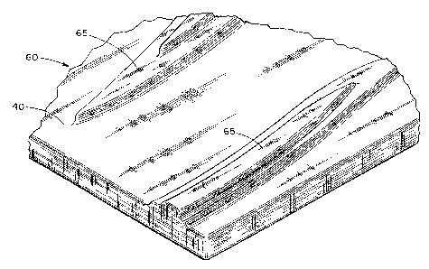
FIG. 13 is a detail perspective view of a portion of a finished panel 60
showing the fabric layer 40 folded around the edge of the panel and formed
over
the design pieces.
FIG. 14 is a perspective view of three panels 60 - 62 assembled together
showing how designs 65 can be continuous from one panel to the next.
DETAILED DESCRIPTION OF THE INVENTION
Turning to FIG. 1, a perspective view is provided of a flat acoustical panel
10. This panel 10 serves as the base or substrate for the present invention.
The
panel 10 can be made of any conventional material suitable for its intended
use,
such as fiberglass. Optionally, the acoustical panel 10 should be air-
permeable if
the present method employs suction to apply a fabric layer, as will be
discussed in
detail below.
FIG. 2 is a perspective view showing design pieces 21 - 28 for creating the
three-dimensional surface being marked out on a fiberglass board 20. FIG. 3
shows these design pieces 21 - 28 being cut out. The pieces 21 - 28 are laid
out
after cutting in FIG. 4. The design pieces 21 - 28 are then used in
constructing
raised three-dimensional surfaces on the flat panel 10. The design pieces 21 -
28
can either be placed singly atop the panel 10, or they can be stacked to any
desired height on the panel 10. For example, FIG. 5 shows two design pieces 21
and 22 stacked on a panel 10 to create a three-dimensional surface with a
visual
effect similar to a contour map. It should be understood that the design
pieces can
have any desired thicknesses, dimensions or cross-sectional shapes to create
aesthetically pleasing three-dimensional surfaces.
After the design pieces 21 - 28 have been cut out, their proper placement
can be marked on the panel 10 for assembly. FIG. 6 is a perspective view
showing the layout of the design being marked on a panel 10 for placement of
the
design pieces 21 - 28. The design pieces 21 - 28 are then bonded with adhesive
30 to the panel 10 and to each other as illustrated in FIG. 7 to build up the
desired
three-dimensional surface on the panel 10. This design can extend over
multiple
panels 10, 11. For example, FIG. 8 is a perspective view showing the design
pieces bonded to two acoustical panels 10, 11 to create a continuous three-

CA 02818123 2013-06-06
-4-
dimensional design. Optionally, the exposed edges of the panel 10 and design
pieces 21 - 28 can be hardened by applying a hardening material 35 (e.g.,
epoxy),
as shown in FIG. 9, to increase structural strength and reduce the risk of
damage
of the edges of the panel assembly. Reinforcing material (e.g., thin sheets of
rigid
paper, cardboard or particle board) can also be bonded or attached to the
edges
of the panel 10 and/or design pieces 21 -28.
Next, the assembled panel 10 and design pieces 21 - 28 are placed in a
spray booth beneath spray nozzles 52 and coated with adhesive 30 as depicted
in
FIG. 10. A thin flexible layer 40 (e.g., fabric) is then applied over the
assembled
panel 10 and design pieces 21 - 28. For example, this step can be done by
moving the panel assembly to a suction table 50 (as shown in FIG. 11), placing
fabric 40 over the assembled panel 10 and design pieces 21 - 28, and then
drawing down the fabric 40 by suction through the panel 10.
Optionally, a layer of air-impermeable flexible material 45 (e.g., a thin
plastic or vinyl sheet) can be temporarily placed over the fabric 40 to assist
in
drawing the fabric 40 into close contact with panel assembly and the adhesive
layer. The air-impermeable layer is then removed, while leaving the fabric
layer 40
in place to bond with the adhesive 30. This temporary air-impermeable layer is
more likely to be needed if the fabric layer 40 is loosely woven or very air-
permeable. FIG. 11 is a perspective view showing the panel assembly placed on
a
suction table 50 with a fabric layer 40 and an air-impermeable cover layer 45
being drawn down by suction down over the panel 10 and design pieces 21 - 28.
FIG. 12 is a perspective view showing a heat machine 54 placed over the
panel assembly in FIG. 11 to further curing of the adhesive 30. This step may
be
optional depending on the adhesive selected. Finally, FIG. 13 is a detail
perspective view of a portion of a finished panel showing the fabric 40 folded
around the edge of the panel and formed over the design pieces to complete the
assembly.
It should be understood that virtually any desired three-dimensional design
can be created on a panel 10 by employing the present invention. The designs
can be limited to a single panel or a particular region of a panel.
Alternatively, FIG.

CA 02818123 2013-06-06
-5-
14 illustrates a series of panels 60, 61 and 62 assembled together showing
designs 65 that span multiple panels.
The above disclosure sets forth a number of embodiments of the present
invention described in detail with respect to the accompanying drawings. Those
skilled in this art will appreciate that various changes, modifications, other
structural arrangements, and other embodiments could be practiced under the
teachings of the present invention without departing from the scope of this
invention as set forth in the following claims.

Representative Drawing
A single figure which represents the drawing illustrating the invention.
Administrative Status

2024-08-01:As part of the Next Generation Patents (NGP) transition, the Canadian Patents Database (CPD) now contains a more detailed Event History, which replicates the Event Log of our new back-office solution.

Please note that "Inactive:" events refers to events no longer in use in our new back-office solution.

For a clearer understanding of the status of the application/patent presented on this page, the site Disclaimer , as well as the definitions for Patent , Event History , Maintenance Fee  and Payment History  should be consulted.

Event History

Description Date
Inactive: COVID 19 - Deadline extended 2020-05-28
Common Representative Appointed 2019-10-30
Grant by Issuance 2016-09-13
Inactive: Cover page published 2016-09-12
Inactive: Final fee received 2016-07-18
Pre-grant 2016-07-18
Notice of Allowance is Issued 2016-04-22
Letter Sent 2016-04-22
Notice of Allowance is Issued 2016-04-22
Inactive: Q2 passed 2016-04-20
Inactive: Approved for allowance (AFA) 2016-04-20
Amendment Received - Voluntary Amendment 2015-07-20
Letter Sent 2015-07-09
Request for Examination Requirements Determined Compliant 2015-06-12
All Requirements for Examination Determined Compliant 2015-06-12
Request for Examination Received 2015-06-12
Inactive: Cover page published 2014-12-15
Application Published (Open to Public Inspection) 2014-12-06
Inactive: IPC assigned 2013-09-12
Inactive: First IPC assigned 2013-09-12
Inactive: IPC assigned 2013-09-04
Inactive: IPC assigned 2013-08-26
Inactive: First IPC assigned 2013-08-26
Inactive: IPC assigned 2013-08-26
Inactive: Filing certificate - No RFE (English) 2013-06-19
Application Received - Regular National 2013-06-19

Abandonment History

There is no abandonment history.

Maintenance Fee

The last payment was received on 2016-05-10

Note : If the full payment has not been received on or before the date indicated, a further fee may be required which may be one of the following

  • the reinstatement fee;
  • the late payment fee; or
  • additional fee to reverse deemed expiry.

Patent fees are adjusted on the 1st of January every year. The amounts above are the current amounts if received by December 31 of the current year.
Please refer to the CIPO Patent Fees web page to see all current fee amounts.

Owners on Record

Note: Records showing the ownership history in alphabetical order.

Current Owners on Record
JACQUE S. HARRISON
DONALD W. HARRISON
Past Owners on Record
None
Past Owners that do not appear in the "Owners on Record" listing will appear in other documentation within the application.
Documents

To view selected files, please enter reCAPTCHA code :


To view images, click a link in the Document Description column (Temporarily unavailable). To download the documents, select one or more checkboxes in the first column and then click the "Download Selected in PDF format (Zip Archive)" or the "Download Selected as Single PDF" button.

List of published and non-published patent-specific documents on the CPD .

If you have any difficulty accessing content, you can call the Client Service Centre at 1-866-997-1936 or send them an e-mail at CIPO Client Service Centre.

({010=All Documents, 020=As Filed, 030=As Open to Public Inspection, 040=At Issuance, 050=Examination, 060=Incoming Correspondence, 070=Miscellaneous, 080=Outgoing Correspondence, 090=Payment})


Document
Description 
Date
(yyyy-mm-dd) 
Number of pages   Size of Image (KB) 
Drawings 2013-06-05 10 367
Description 2013-06-05 5 217
Claims 2013-06-05 3 106
Abstract 2013-06-05 1 9
Representative drawing 2014-11-16 1 42
Claims 2015-07-19 2 34
Maintenance fee payment 2024-05-30 47 1,945
Filing Certificate (English) 2013-06-18 1 156
Reminder of maintenance fee due 2015-02-08 1 112
Acknowledgement of Request for Examination 2015-07-08 1 187
Commissioner's Notice - Application Found Allowable 2016-04-21 1 162
Request for examination 2015-06-11 1 38
Amendment / response to report 2015-07-19 3 72
Final fee 2016-07-17 1 38