Note: Descriptions are shown in the official language in which they were submitted.
CA 02818134 2013-05-22
Apparatus for Boosting Fire and Collecting Ash
BACKGROUND OF INVENTION
1. FIELD OF INVENTION
The present invention relates to barbecue and, more particularly, to
an apparatus for boosting fire and collecting ash in barbecue.
2. RELATED PRIOR ART
Barbecue is a primitive way of cooking food. In modern barbecue,
solid fuel is often burned in a barbecue grill. Such solid fuel may be
wood or coal. The solid fuel is spread in the barbecue grill. It takes
quite some time to light a fire on the solid fuel. In the combustion of the
solid fuel, ash is produced. It is troublesome to collect the ash.
To reduce the time for lighting a fire on the solid fuel, there have
been devised various apparatuses for boosting fire such as those disclosed
in Taiwanese Patents 1275639, 1370222 and M332172 and U.S. Patent
Nos. 1536692, 3191556, 5197455, 5230325, 5469835 and 6913013.
However, these apparatuses are not useful for collecting ash produced
from the combustion of the solid fuel.
There have been devised various apparatuses for collecting the ash
such as those disclosed in U.S. Patent No. 6182559 and U.S. Patent
Application Publication No. 20060054158. However, these apparatuses
are not useful for boosting fire.
As disclosed in U.S. Patent No. 3209743, a barbecue grill includes a
bowl 11, a receptacle 23, a grate 26 and closure means. The bowl 11
includes a bottom element 24 that includes a grate 26 formed between
two L-shaped flanges 27. The grate 26 inherently includes holes 25
1
CA 02818134 2013-05-22
defined therein. The receptacle 23 includes a side wall 29, a peripheral
flange 40 formed on an upper edge of the side wall 29, and a cup 30
welded to a lower edge of the side wall 29. Holes 32 are defined in the
cup 30. The closure means includes a plate 35 pivotally connected to
the cup 30 by a rivet 36. In use, coal 43 is placed on the grate 26 while
combustible material 33 is placed in the receptacle 23. The plate 35 in
placed in an opening position where the plate 35 opens the holes 32.
The combustible material 33 is ignited by a burning match. The
peripheral flange 40 is engaged with the L-shaped flanges 27 to attach the
receptacle 23 to the bowl 11. The coal 43 is ignited by the burning
combustible material 33 and spread evenly on the bottom element 24 of
the bowl 11. The plate 35 is pivoted to a closing position where the
plate 35 covers the holes 32. After the combustion of the coal 43, ash is
collected in the receptacle 23 through the grate 26. The receptacle 23
alone cannot be used to contain the coal 43. That is, the receptacle 23
cannot be used to boost fire without the synchronous use of the bowl 11
of the barbecue grill.
Therefore, the present invention is intended to obviate or at least
alleviate the problems encountered in prior art.
SUMMARY OF INVENTION
In one embodiment, the present invention provides a compact
apparatus for boosting fire and collecting ash.
To achieve the foregoing, the apparatus includes a cup, a grate and a
gate. The cup includes an upper chamber, a lower chamber, and
apertures in communication with the lower chamber. The grate includes
2
CA 02818134 2013-05-22
at least one aperture. The grate is placed in the cup between the upper
and lower chambers. The gate includes at least one aperture
corresponding to the aperture of the grate. The gate is pivotally placed
in the cup between a first position and a second position. The aperture
of the gate is in communication with the aperture of the grate to
communicate the upper chamber with the lower chamber as the gate is in
the first position. The gate shuts the aperture of the grate to shut the
upper chamber from the lower chamber as the gate is in the second
position.
Other advantages and features of the present invention will be
apparent from the following description referring to the attached
drawings.
BRIEF DESCRIPTION OF DRAWINGS
The present invention will be described via detailed illustration of
three embodiments referring to the drawings wherein:
FIG. 1 is an exploded view of an apparatus for boosting fire and
collecting ash according to the first embodiment of the present invention;
FIG. 2 is a perspective view of the apparatus shown in FIG. 1;
FIG. 3 is an enlarged, partial, cross-sectional view of the apparatus
shown in FIG. 1;
FIG. 4 shows operation of the apparatus shown in FIG. 3;
FIG. 5 is a perspective view of an apparatus for boosting fire and
collecting ash according to the second embodiment of the present
invention;
FIG. 6 is an exploded view of an apparatus for boosting fire and
3
CA 02818134 2013-05-22
collecting ash according to the third embodiment of the present invention;
FIG. 7 is a cut-away view of the apparatus shown in FIG. 6 in
operation;
FIG. 8 is an enlarged, partial, side view of the apparatus shown in FIG.
7;
FIG. 9 is a side view of a barbecue grill and the apparatus shown in
FIG. 7;
FIG 10 is an enlarged, partial, perspective view of the barbecue grill
and the apparatus shown in FIG. 9; and
FIG. 11 is a perspective view of the barbecue grill and the apparatus
shown in FIG. 10.
DETAILED DESCRIPTION OF EMBODIMENTS
Referring to FIGS. 1-4, there is shown an apparatus 10 for boosting
fire and collecting ash according to a first embodiment of the present
invention. The apparatus 10 includes a cup 20 and a gate 11.
The gate 11 includes a flange 13, a bottom element 14, a wall 12
formed between the flange 13 and the bottom element 14, at least one
operation element connected to the flange 13, and apertures 16 defmed in
the bottom element 14. The at least one operation element includes two
opposite tabs 15 extending from the flange 13.
The cup 20 includes a base 40, a cylinder 41 and a handle 42. The
base 40 includes a wall 27 extending downward from a grate 23 that
includes apertures 26 defined therein. The wall 27 includes an upper
portion that is smaller than a lower portion thereof. The upper portion
of the wall 27 is fit in the cylinder 41. Preferably, the upper portion of
4
CA 02818134 2013-05-22
the wall 27 is welded to the cylinder 41. Apertures 45 are defined in a
lower portion of the wall 27. The stepped wall 27 includes an edge 22
that can be referred to as the lower edge of the cup 20. The base 40
defines a chamber 25 that can be referred to as the lower chamber of the
cup 20.
The cylinder 41 includes an upper edge 21 that can be referred to as
the upper edge of the cup 20. The cylinder 41 defines a chamber 24 that
can be referred to as the upper chamber of the cup 20. The cylinder 41
includes two opposite slots 46 defined therein. Two pegs 47 are formed
on an internal side of the cylinder 41. The apparatus 10 of the present
invention can be attached to a cylinder 10 of a conventional barbecue grill
such as the one disclosed in U.S. Patent No. 6182559 by inserting the
pegs 47 of the present invention in the slots 11 of the conventional
barbecue grill.
The handle 42 is attached to an external side of the cylinder 41 by
welding for example. An insulating grip 43 is attached to the handle 42.
The insulating grip 43 includes two pieces of wood or plastics for
sandwiching a portion of the handle 42. A radiator 44 is attached to the
external side of the cylinder 41. Preferably, the radiator 44 is placed
near the handle 42.
The gate 11 is substantially placed in the cup 20. However, each of
the tabs 15 extends from the cup 20 through a corresponding one of the
slots 46. The gate 11 is pivotally connected to the grate 23 by a
fastening unit 30 that includes a screw 31 and a butterfly nut 32. The
tabs 15 are operated to pivot the gate 11 on the grate 23 between a first
5
CA 02818134 2013-05-22
position shown in FIG. 3 and a second position shown in FIG. 4.
As the gate 11 is placed in the first position on the grate 23, the
apertures 16 are closed by the grate 23. Thus, air is not allowed to travel
into the upper chamber 24 from the lower chamber 25. The apparatus
10 is used as an ash-collecting device.
As the gate 11 is placed in the second position on the grate 23, the
apertures 16 are opened by the grate 23. Thus, air is allowed to travel
into the upper chamber 24 from the lower chamber 25 into which the air
travels from the exterior of the cup 10 through the apertures 45. The
apparatus 10 is used as a fire-boosting device. Coal 35 is placed in the
upper chamber 24. Highly combustible material 34 such as tinder is
placed in the lower chamber 25. The highly combustible material 34 is
ignited by a burning match (not shown) for example. The coal 35 can be
ignited by the burning tinder 34. It should be noted that the coal 35 can
easily be ignited by the burning tinder 34.
Referring to FIG. 5, there is shown an apparatus for boosting fire and
collecting ash according to a second embodiment of the present invention.
The second embodiment is like the first embodiment except two things.
At first, the cup 20 includes a flange 50 extending from the upper edge 21
thereof. Secondly, the cup 20 includes windows 51 in communication
with the upper chamber 24. The apparatus of the second embodiment
can be attached to the barbecue grill of U.S. Patent No. 3209743 by
engaging the flange 50 with the L-shaped flanges 27 of the barbecue grill
disclosed in U.S. Patent No. 3209743. The windows 51 are useful for
introducing air into the bowl 11 of the barbecue grill disclosed in U.S.
6
CA 02818134 2013-05-22
Patent No. 3209743.
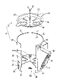
Referring to FIGS. 6-11, there is shown an apparatus for boosting fire
and collecting ash according to a third embodiment of the present
invention. The third embodiment is like the second embodiment except
four things. At first, the base 23 is separated from the wall 27. The
wall 27 is formed as an extension from the cylinder 41.
Secondly, the gate 11 includes a wall 52 instead of the wall 12. The
wall 52 is higher than the wall 12. The wall 52 includes windows 55
corresponding to the windows 51. Moreover, the wall 52 includes two
opposite apertures 56.
Thirdly, there is no flange, such as the flange 13, extending from an
edge 54 of the wall 52. Finally, the at least one operation element
includes a lever 60 instead of the tabs 15. The lever 60 includes a
threaded portion 61, a grip 62 opposite to the threaded portion 61, and a
flat portion 63 near the grip 62. The grip 62 is a hooked or lopped
portion of the lever 60.
The lever 60 is inserted in the apertures 56 via the slots 46. The
threaded portion 61 of the lever 60 is placed out of one of the slots 46
while the grip 62 and the flat portion 63 of the lever 60 are placed out of
the other slot 46. The threaded portion 61 of the lever 60 is engaged
with a butterfly nut 32. Thus, the gate 11 is kept in the cup 20 by the
lever 60, which is kept on the cup 20 by the flat portion 63 and the
butterfly nut 32.
In another embodiment, the wall 52 includes only one aperture 56
and the cylinder 41 also includes only one slot 46. The butterfly nut 32
7
CA 02818134 2013-05-22
is placed against an internal side of the wall 52 while the flat portion 63
of the lever 60 is placed against the external side of the cylinder 41.
Referring to FIG 7, coal 35 is placed in the gate 11 while tinder 34 is
placed below the grate 23. The tinder 34 is ignited by a burning match
(not shown). The coal 35 can be ignited by the burning tinder 34.
Referring to FIG 8, each of the slots 46 is defined between an upper
edge and a lower edge. The lower edge includes a boss 64 formed
thereon. The upper edge includes a recess 65 defined therein. The
width of each of the slots 46 remains constant from a left end to a right
end. The width of the slots 46 is larger than the diameter of the lever 60
so that the lever 60 can be smoothly pivoted in the slots 46.
When the lever 60 is pivoted to the right ends of the slots 46, the
windows 51 are completely closed by the gate 11 while the apertures 26
are completely opened, i.e., the apertures 26 are in perfect communication
with the apertures 16. In this position, the apparatus 10 is suitable for
boosting fire for providing the best stack effect.
When the lever 60 is pivoted to the left ends of the slots 46, the
windows 51 are completely opened, i.e., the windows 51 are in perfect
communication with the windows 55. The apertures 26 are completely
closed by the gate 11. In this position, the apparatus 10 is suitable for
collecting ash for providing the best stack effect
The boss 64 is used as an indicator. When the lever 60 is placed to
the right of the bosses 64, the apparatus 10 is suitable for boosting fire for
providing the best stack effect. When the lever 60 is placed to the left of
the bosses 64, the apparatus 10 is suitable for collecting ash for providing
8
CA 02818134 2013-05-22
the best stack effect.
Referring to FIG. 9, there is shown a barbecue grill 70 that includes a
bowl 71 and a cover 72. The coal 35 is moved into the bowl 71 from the
apparatus 10 after the coal 35 is ignited. The burning coal 35 is evenly
spread in the bowl 71.
Referring to FIGS. 10 and 11, the bowl 71 includes an opening 74.
An engagement piece 73 is welded to the bottom thereof around the
opening 74. The engagement piece 73 includes two parallel tracks 75
and a stop 76. The tracks 75 and the stop 76 are identical L-shaped
flanges in different positions. The flange 50 is slid on the tracks 75 so
that the flange 50 is stopped by the stop 76. Thus, the apparatus 10 is
connected to the bowl 71. The apparatus 10 is used for collecting ash
from the bowl 71.
The present invention has been described via the detailed illustration
of the embodiments. Those skilled in the art can derive variations from
the embodiments without departing from the scope of the present
invention. Therefore, the embodiments shall not limit the scope of the
present invention defined in the claims.
9