Note: Descriptions are shown in the official language in which they were submitted.
CA 02818595 2013-05-21
WO 2011/063265
PCT/US2010/057481
LIGHT ARRAY MAINTENANCE SYSTEM AND METHOD
Related Applications
[0001] This application claims priority to United States Patent
Application serial number 12/722,453 (entitled LIGHT ARRAY
MAINTENANCE SYSTEM AND METHOD, filed March 11, 2010) which is
incorporated herein by reference, and claims priority to United States
Provisional Application serial number 61/263,312 (entitled LIGHT ARRAY
MAINTENANCE SYSTEM AND METHOD, filed November 20, 2009) which
is incorporated herein by reference.
Background
[0002] Light emitting diodes have long been used individually or
grouped together as background or indicating lights in electronic devices.
Because of the efficient light production, durability, long life, and small
size
light emitting diodes were ideal for electronic applications.
[0003] Higher powered light emitting diodes also are used in
applications where a stronger emission of light is needed. In some high
intensity
applications, multiple fixed sets of serially connected light emitting diodes,
each
set having a common voltage drop are used to obtain desired luminescence. The
sets are formed along rails or bars, where an entire rail or bar may be
replaced by
the manufacturer if any portion of the rail becomes defective. If the
manufacturer is located a long distance, or has a backlog of repairs to make,
it
can take a long time to obtain such a repair. Such applications may be used
indoors or outdoors. The light emitting diodes electrically connected operate
as
a single application, sealed and protected as a single linear group.
Replacement
of the whole group of fixed light emitting diodes is needed if just one diode
fails.
[0004] In outdoor settings, an array of light emitting diodes may
consist
of multiple sets of light emitting diodes. One or more of the diodes may be
inoperative, due to either wearing out, defective manufacturing, or vandalism.
It
may be difficult to detect whether one or more light emitting diodes are
inoperative due to their brightness. Further, organizations, such as
municipalities may have many such arrays operating over a wide geographic are.
While reports from citizens may be collected to help identify light emitting
1
CA 02818595 2013-05-21
WO 2011/063265
PCT/US2010/057481
diodes that need replacing, it is difficult to ensure that all inoperative
light
emitting diodes are replaced. Maintenance thus becomes a difficult
proposition.
Brief Description of the Drawings
[0005] FIG. 1 is a top view of a matrix of light emitting diode modules
according to an example embodiment.
[0006] FIG. 2A is a top view of a matrix including sockets for light
emitting diode modules according to an example embodiment.
[0007] FIG. 2B is a top view of a circuit board for mating with the
matrix of FIG. 2B according to an example embodiment.
[0008] FIG. 3 is a perspective view of a high intensity light
emitting
diode module according to an example embodiment.
[0009] FIG. 4 is block schematic representation of wired sockets for
a
matrix of modules according to an example embodiment.
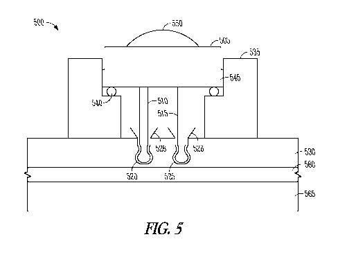
[0010] FIG. 5 is a block cross sectional view of a module supported in a
socket according to an example embodiment.
[0011] FIG. 6 is a block cross sectional view of a module having a
different connection mechanism to provide a sealed connection with a socket
according to an example embodiment.
[0012] FIG. 7 is a block cross sectional view of a module having a
different connection mechanism to provide a sealed connection with a socket
according to an example embodiment.
[0013] FIG. 8 is a block cross sectional view of a module having a
different connection mechanism to provide a sealed connection with a socket
according to an example embodiment.
[0014] FIG. 9 is a top view of connectors on a board for providing
electrical connection to a module according to an example embodiment.
[0015] FIG. 10 is a block cross section view of an alternative
module
supported in a socket according to an example embodiment.
[0016] FIG. 11 is a block cross section view of an alternative module for
plugging into a board according to an example embodiment.
[0017] FIG. 12 is a top view of a connector and side view of a
module
for plugging into the connector according to a further example embodiment.
2
CA 02818595 2013-05-21
WO 2011/063265
PCT/US2010/057481
[0018] FIG. 13 is a block diagram of a lighting system according to
an
example embodiment.
[0019] FIG. 14 is a flow chart illustrating a method of collecting
data
according to an example embodiment.
[0020] FIG. 15 is a flow chart illustrating a method of controlling the
lighting system conesponding to the collected data according to an example
embodiment.
[0021] FIG. 16 is a block diagram of a lighting system having
multiple
light anays according to an example embodiment.
[0022] FIG. 17 is a flow chart illustrating a method of controlling the
lighting system having multiple light arrays according to an example
embodiment.
[0023] FIG. 18 is a block diagram of an example computer system for
implementing one or more methods according to an example embodiment.
[0024] FIG. 19 is a block diagram of a light fixture that provides
communications related to light replacement according to an example
embodiment.
[0025] FIG. 20 is a block circuit diagram illustrating a light
socket with
detection circuitry according to an example embodiment.
[0026] FIG. 21 is a block diagram of a remote control device for
programming light fixtures according to an example embodiment.
[0027] FIGs. 22, 23, 24, and 25 illustrate perspective views of a
light
module and various aspects of a light fixture that utilizes replaceable light
modules according to example embodiments.
Detailed Description
[0028] In the following description, reference is made to the
accompanying drawings that form a part hereof, and in which is shown by way
of illustration specific embodiments which may be practiced. These
embodiments are described in sufficient detail to enable those skilled in the
art to
practice the invention, and it is to be understood that other embodiments may
be
utilized and that structural, logical and electrical changes may be made
without
departing from the scope of the present invention. The following description
of
3
CA 02818595 2013-05-21
WO 2011/063265
PCT/US2010/057481
example embodiments is, therefore, not to be taken in a limited sense, and the
scope of the present invention is defined by the appended claims.
[0029] The present application describes several embodiments of
light
fixtures, some of which have arrays of replaceable light emitting diode
modules.
Maintaining light fixtures includes identifying a high intensity light
emitting
diode that needs replacing in a light fixture having a high volume light
emitting
diode lighting array having a plurality of electrical sockets supported by a
matrix
and forming a matrix of electrical sockets. An ID of the light fixture is
provided,
and the light fixture transmits the ID and an indication that a light emitting
diode
needs replacing. The ID uniquely identifies the light fixture and has an
associated location of the light fixture.
[0030] Further embodiment are described that display light in
accordance
with a program that may be representative of a pre-recorded outdoor light
sequence, such as a day in the sun with clouds drifting past the sun. The
result is
a simulated day in the sun. The natural variations in color and intensity of
the
light provided by such a recording or program may provide a relaxing
environment. Light can affect the production of melatonin by the pineal gland
in
humans. Melatonin can be important in regulating circadian rhythms and sleep
cycles. Natural sunlight, including variations, may affect melatonin
production.
By simulating such natural sunlight, productivity of office and other indoor
workers may be improved.
Replaceable module embodiments
[0031] In one set of embodiments involving arrays of replaceable
light
emitting diodes, a high intensity light emitting diode light fixture for
producing
large volume of light for lighting large areas, such as parking lots, parking
ramps, highways, streets, stores, warehouses, gas station canopies, etc., is
illustrated in FIG. 1 generally at 100. FIG. 1 is a top view of light fixture
100,
which includes a rigid matrix 105. Multiple high intensity light emitting
diodes
may be encapsulated into modules 110, which may be seen in FIG. 1 through
cylindrical cooling structures 120. In this view, the modules provide light
pointing away from the surface of the figure.
[0032] In one embodiment, the cooling structures 120 and modules 110
are supported by the matrix 105, which is formed of aluminum in one
4
CA 02818595 2013-05-21
WO 2011/063265
PCT/US2010/057481
embodiment to provide both strength and heat conduction to help keep the
modules 110 cool. A board 130, such as a circuit board, may be placed
integrated with the cooling structures 120 and provides appropriate electrical
conductors between the modules 110. In one embodiment, board 130 may be a
standard circuit board with metallization for forming the conductors. In one
embodiment, a frame 140 may be formed around the matrix and be integrated
with the matrix.
[0033] The matrix and cooling structures 120 may be formed of
aluminum or other material that provides adequate structural support, is light
weight, and conducts heat well. A plurality of electrical sockets 150 may be
formed on the matrix between the cooling structures and are secured to the
board
130 in one embodiment, forming a matrix of electrical sockets 150 that may be
electrically interconnected in two dimensions by the board 130. One or more
light emitting diode modules 110 may be individually removable and replaceable
within any individual electrical socket within the matrix, which may be rigid
in
one embodiment and may be secured within the matrix 105 by an epoxy or other
filler material having suitable heat conducting and retentive properties to
ensure
the board 130 is securely held in place over the sockets 150.
[0034] As may be seen in FIG. 1, more sockets than can accommodate
modules may be provided in various patterns. The additional sockets provide
flexibility for a multitude of lighting needs. In one embodiment, the sockets
may provide for the use of an optimum number of modules to provide a high
volume of lighting for outdoor applications, such as parking lots, parking
ramps,
highways, streets, stores, warehouses, gas station canopies. For lower volume
lighting applications, fewer modules may be used in fewer sockets. For each
configuration of sockets with modules, the electrical connections may be
modified to provide a proper voltage for each module.
[0035] FIG. 2A is a top view of matrix 105 including sockets 150 for
light emitting diode modules according to an example embodiment. As shown
the matrix 105, with cooling structures 120 and sockets 150 have some depth to
them that provides both structural support may be formed of heat conducting
material. The sockets are disposed between the cooling structures such that
heat
is easily conducted to the cooling structures.
5
CA 02818595 2013-05-21
WO 2011/063265
PCT/US2010/057481
[0036] FIG. 2B is a top view of circuit board 130 for mating with
the
matrix of FIG. 2B according to an example embodiment. The board 130 has
openings conesponding to cooling structures 120 in one embodiment, and sets of
connectors conesponding to the sockets when coupled to the matrix.
[0037] Each individual light emitting diode module as shown in further
detail at 300 in FIG. 3 may include a base 310 and a light emitting diode 320.
The base may be configured and arranged for fitted electrical engagement
within
the electrical socket 150. Light emitting diode modules 300 may fit in the
electrical sockets 150 though multiple different types of connections. In
various
embodiments, the light emitting diode 320 may be different colors with most
colors being currently commercially available.
[0038] The base 310 of the light emitting diode module 300 may
include
heat dissipating radial fins 330 to dissipate heat away from the electrical
socket
150 and leads or contacts 340 for coupling to connectors on board 130 for
providing power to the light emitting diode 320. Because the light emitting
diode module 300 may be used for both inside and outside applications, some
embodiments are able to withstand a large ambient temperature range provided
it
is not too warm for proper operation, and may also withstand inclement weather
conditions including rain, snow, ice, dust, winds up to about 150 miles per
hour,
etc., while still efficiently emitting light. The heat dissipating fins 330
may
extend radially from a top of the base 310, drawing heat away from the light
emitting diode 320 and acting as a heat sink to prevent damage to the light
emitting diode or the surrounding components. The fins may couple to a heat
fin
ring 350 which may provide stability and a means of permitting ease of
handling
when assembling or replacing modules 300 in sockets 150.
[0039] FIG. 4 is a block diagram schematic representation of a
connector
board for a high intensity light emitting diode array shown generally at 400.
Openings in the board for the cooling structures are not shown. In one
embodiment, a board 410 is provided with a positive connector 415 and a
negative connector 420 for connection to a power source and driver, not shown.
Positive connector 415 is electrically coupled via a connector 425 to a first
socket 430. Given a supply of 24 volts across connectors 415 and 420, ten
sockets are serially electrically coupled, ending with socket 435, which in
turn,
is coupled via connector 440 to negative connector 420. These connections,
6
CA 02818595 2013-05-21
WO 2011/063265
PCT/US2010/057481
together with intermediate serial connections to eight other sockets provides
a
voltage drop of 2.4 volts DC for each light emitting diode plugged into the
socket. This ensures that each light emitting diode will receive the proper
voltage for proper operation.
[0040] If a different supply level is provided, and/or different light
emitting diodes are used with different voltage drops, it is a simple matter
to
divide the supply by the voltage drop to determine how many sockets should be
connected serially. The board may then be reconfigured consistent with the
number of sockets needed. As shown in FIG. 4, there are four such sets of
serially connected sockets, each being coupled between the positive and
negative
connectors 415 and 420. Many other different configurations are possible.
[0041] In still further embodiments, adaptive power supplies may be
used, and the number of modules in series may be varied with the supply
adapting to the proper output required to drive the modules. All sockets may
be
active with such drivers and modules plugged in as desired. In some
embodiments, modules may be removed or added in series if needed to be
compatible with the supply and driver circuitry. All the sockets may be wired
in
series in one embodiment. Plugs to short circuit open sockets may be used to
maintain the series connection, or suitable bypass circuitry may be used to
maintain a series connection if modules in sockets have malfunctioned, or
sockets are not used in some lighting applications.
[0042] In one embodiment, the cun-ent sockets are ananged in an oval
shape, but many other shapes may be easily used. The board 410 may be
suitably shaped to conform to the sockets to provide a shape suitable for
aesthetic design purposes. Similarly, the matrix 105 as shown in FIG. 1 may
also take many different shapes, from rectangular or circular as shown to just
about any shape desired, such as "u" shaped or kidney bean shaped to name a
few. Further, elongated shapes of one or more rows of sockets may be provided.
[0043] The matrix 105 and board 130 in some embodiments may be
made of any weather resistant metal such as aluminum or other material
suitable
for dissipating heat. In one embodiment, the electrical sockets are in a
uniformly
disbursed triangular matrix in relation to each other and may be part of a
cast
matrix 105.
7
CA 02818595 2013-05-21
WO 2011/063265
PCT/US2010/057481
[0044] In one embodiment, the electrical sockets 150 may be designed
to
accommodate a removable and replaceable light emitting diode module with
different connection types including, but not limited to, screw-in or Edison
type
connections, a bayonet-type connection, and snap-in or friction connection as
illustrated at 500 in FIG. 5.
[0045] In FIG. 5, a module 505 is secured via conducting pins 510,
515
into mating connectors 520, 525 in a board 530. The conducting pins and
mating connectors provide for a snap-in or friction connection that holds the
module 505 securely within a socket 535. In one embodiment, the mating
connectors 520 and 525 may be provided with guides 526 that ensure that the
pins are properly inserted and guided into the female mating connectors 520,
525, which may be made of brass in one embodiment and be spring loaded from
the sides to retentatively engage the pins 510, 515. The female connectors may
extend partly above the board, or within the board in various embodiments.
When within the board, the board essentially has a larger opening than the
diameter of the pins, and narrows to the point of the snap-in or friction
connection portion of the matting connectors.
[0046] In one embodiment, a sealing member such as a ring, disk or
washer 540 is positioned between the module 505 and a surface of the socket
535. The sealing member 540 is compressed when the module 505 is fully
secured by the pins and mating connectors to provide a water tight seal and
protect the electrical connections from elements which might degrade the
electrical contact formed by such connections. In various embodiments, the
sealing member may be formed of rubber, latex, Teflon, silicon rubber or like
compressible material. To provide for larger tolerances with respect to the
thickness of the board 530 and the distance of the connectors 520, 525 from
the
module when seated in the socket, the compressible sealing member may be
formed with a hollow center in some embodiments. In further embodiments, the
sealing member operates to provide a seal over a wide depth of compression.
[0047] In a further embodiment, plugs may be formed in the same shape
as module 505, having pins that mate with the mating connectors 520, 525 to
provide a seal around sockets that are not used for operational modules. The
pins of such plugs may be electrically isolated from each other to ensure that
no
short circuits occur, or may provide a short circuit to properly maintain a
series
8
CA 02818595 2013-05-21
WO 2011/063265
PCT/US2010/057481
connection in a pre-wired string of sockets. Such plugs ensure integrity of
all
electrical connections in the board when properly used in all sockets not
containing modules 505.
[0048] The ability to easily remove and replace modules in a sealing
manner facilitates maintenance and repair of high intensity large volume
matrix
lighting solutions. Each individual light emitting diode module may be removed
from an individual socket within the matrix. Because the individual light
emitting diode modules are individually replaceable, if one module fails there
is
no need to replace an entire bundle or group of electrical sockets or modules.
Simple removal and replacement of the failed module may be quickly
performed. Furthermore, light emitting diode modules emitting different colors
may be rearranged within the matrix to produce different color arrangements
without replacement of the entire bundle of electrical sockets or modules.
[0049] Module 505 also illustrates a lens 550 coupled to the light
emitting diode within module 505 and providing a protective seal. The lens 550
may be placed on and adhered to a filling material surrounding the actual
light
emitting diode. As the filling material solidifies, the lens may be securely
fastened to the filling material. Many different types and shapes of lenses
may
be used. For large area high intensity lighting applications, the lens may be
shaped to provide directional lighting, or a widely dispersed beam of light
such
that when all the modules in an array are properly oriented, a desired pattern
of
light is provided to light a large area, such as a parking lots, parking
ramps,
highways, streets, stores, warehouses, gas station canopies. Similarly,
different
lenses may be used for many different applications, such as for forming spot
lights, narrow beams from each module may be desired.
[0050] Module 505 may also be provided with guides 545, which along
with mating guides in a socket, ensure that the module is inserted into the
socket
in a desired orientation. In one embodiment, the guides 545 may be ridges
extending outward from the module and mating with grooves in the module to
provide a guide. In further embodiments, the grooves may be on the module
with mating ridges on the socket. Many different shapes and combinations of
grooves and ridges may be provided in various embodiments.
9
CA 02818595 2013-05-21
WO 2011/063265
PCT/US2010/057481
[0051] In yet a further embodiment, board 530 may be formed with a
filling material 560, and a further board 565. Such a combination provides a
seal
for the conductors on the board and protects them from the elements.
[0052] FIG. 6 is a further embodiment 600 of a screw in type of
connector, commonly refened to as an Edison connector. A sealing member is
also provided. In this embodiment, a simple cylinder may be used as the
socket,
with the top portion of the module with the sealing member simply compressed
against the tope of the socket when the module is fully engaged in a retentive
relationship with the socket.
[0053] FIG. 7 is a further embodiment 700 of a bayonet type connector,
also having a sealing member that is similarly compressed.
[0054] FIG. 8 is an alternative embodiment 800 to the module 505 of
FIG. 5, where the sealing member 805 is positioned over the base 810 of module
800. The pins are also similar in that they provide friction fit with
connectors on
aboard.
[0055] FIG. 9 is a block diagram schematic view of the bottom of a
socket 900, into which pins of the modules may be inserted. Six openings 905
are illustrated, representative of connectors for three differently oriented
sets of
pins. Also shown are grooves for providing a guide so modules are properly
inserted. In one embodiment, the board may have three or more different sets
of
wiring to provide different circuits for different types of LED modules, such
as
different color LEDs. The different circuits may then be used to independently
control the different color LEDs in a desired manner, and as further discussed
below to provide different color and intensity light. The differently oriented
sets
of pins along with grooves in one embodiment are formed to ensure that a light
of one color may only be plugged into a socket in a desired manner to connect
to
the desired circuit. In further embodiments, signals to control of lights may
be
multiplexed onto one or more control lines to provide separate circuits for
desired control of lights without having to plug them into the socket in
different
alignments. Still further, sockets may be prewired for a certain type of LED
module. In still further embodiments, sockets may be twisted or otherwise
oriented within a socket to make contact to a desired circuit.
[0056] In one embodiment, a circuit board may have 120 available
sockets for modules, to allow flexibility in positioning modules. In some
CA 02818595 2013-05-21
WO 2011/063265
PCT/US2010/057481
embodiments, different types of modules, such as different color modules may
be interspersed throughout the board. In one example, 90 white light modules,
and 30 yellow light modules may be properly inserted into sockets and
independently controllable, either by separate circuits, or predetermined
wiring.
Many other different combinations and total numbers of sockets per circuit
board may be used in further embodiments, including boards that support 60 to
90 sockets, 90 to 120 sockets, and 120-160 sockets for example.
[0057] FIG. 10 is an alternative embodiment of a module 1000 plugged
into a socket 150. In this embodiment, socket 150 has a flange 1005 at a
module
receiving end that operates to provide a surface for compression of sealing
material 1010 between flange 1005 and a ring 1015 formed on a base of module
1000. Socket 150 also has a second flange 1020 formed on a second end that
abuts board 1025. In this embodiment, pins 1027, 1028 extend a short distance
from a body 1030 of module 1000 to mate with female connectors 1035 and
1040. The female connectors 1035, 1040 may extend beyond the circuit board
into the compressible adhesive material 1045 in some embodiments.
[0058] FIG. 11 shows an alternative module 1100, wherein the female
connectors 1105 and 1110 extend significantly into a compliant adhesive
material 1115 between boards 1120 and 1125. The material 1115 provides
additional spring force for maintaining retentive force on the pins via female
connectors 1105 and 1110. In one embodiment, the material 1115 may be a
liquid rubber, latex, or silicon type material that is pliable and provides
good
adhesion over the boards.
[0059] FIG. 12 is a top view of multiple sets of female connectors
1210
on a board 1215 for mating with pins of a module 1230. Grooves 1220 are also
provided in the sides of the socket conesponding to the connectors to provide
for
guiding the module 1230 having a pair of mating ridges 1235. In one
embodiment, the module may be coupled to one of three different sets of
connectors by rotating the module and inserting it. The positions in which the
module may be inserted may be referred to as A, B and C in one embodiment.
Position A may correspond to wiring on the board such that 80 modules may be
inserted into sockets to provide lighting for an application requiring that
amount
of light. Position B may accommodate 120 modules, while position C may
accommodate 160 modules. The particular numbers of modules may be varied
11
CA 02818595 2013-05-21
WO 2011/063265
PCT/US2010/057481
considerably in different embodiments. In one embodiment, two grooves 1220
may be provided, and rotated to different positions to ensure that the module
is
properly inserted depending on the application desired. Templates may also be
used for each different configuration to help a user insert modules into the
proper sockets. After use of the template, the remaining open sockets may have
plugs inserted to ensure that the lighting fixture is properly sealed.
Light programs
[0060] The functions or algorithms described herein may be
implemented in software or a combination of software and human implemented
procedures in one embodiment. The software may consist of computer
executable instructions stored on computer readable media such as memory or
other type of storage devices. Further, such functions conespond to modules,
which are software, hardware, firmware or any combination thereof. Multiple
functions may be performed in one or more modules as desired, and the
embodiments described are merely examples. The software may be executed on
a digital signal processor, ASIC, microprocessor, or other type of processor
operating on a computer system, such as a personal computer, server or other
computer system.
[0061] In various embodiments of the present invention, one or more
light programs are used to control both the color and intensity of light
emitted
from one or more arrays of light emitting diode (LED) lights. In one
embodiment, light color and intensity may be measured in an outdoor setting
over the course of a day from morning to evening. Both the color, as measured
on a Kelvin temperature scale, and a photometer are used to digitally measure
light color and intensity over the course of the day. In one embodiment,
several
such days are recorded. Seven days worth of such light days may be recorded in
one embodiment and then serially or randomly used to control the LED lights in
an indoor space, such as an office. Such days may include clouds, such as
cumulus clouds drifting across the sun, adding more variety and comfort to the
light pattern experienced by occupants of the indoor space.
[0062] In one embodiment, the intensity of the light may be
maintained
at a desired sufficient level to facilitate office work. A threshold may be
set to
override periods when the recorded day that may dip below the threshold. For
12
CA 02818595 2013-05-21
WO 2011/063265
PCT/US2010/057481
instance, a thick cloud may obscure a significant amount of sunlight, bringing
the light intensity during playback of the recording to a level below a
desired
level and interfere with working. The threshold may be used to increase the
brightness, modify the color, or both, to ensure a level of light that does
not
interfere with work. The threshold may further be adjusted to levels that
promote a feeling of well being, while remaining above an ergonomically
acceptable level.
[0063] The changes in light level in one embodiment, may be fairly
subtle so that it is usually only subconsciously apparent. By removing
extremes,
the changes in light are not annoying, but rather may have a calming or
relaxing
effect on humans.
[0064] Kelvin temperature is a numerical measurement that describes
the
color appearance of the light produced by a light source, and the color
appearance of the light source itself, expressed on the Kelvin (K) scale.
[0065] In application, the Kelvin temperature of light sources is used to
categorize them as warm, neutral or cool sources. The terms are not directly
related to temperature; instead, they describe how the light source appears
visually. Warm sources actually have a lower color temperature (3500K or
less),
producing a red-yellow appearance similar to natural morning light. Neutral
sources (between 3500K and 4100K) tend to have a yellow appearance. A light
source with a color temperature of 5000K is considered pure white light (Full
Spectrum) with the lamp becoming more blue in color as the color temperature
is increased.
[0066] Warm light sources are traditionally used for applications
where
warm colors or earth tones dominate the environment, and where there is a need
to impart a feeling of comfort, coziness and relaxation. Cool light sources
(5000K to 7000K+) provide a white light, similar to full daylight. In prior
lighting arrangements, such white light has been associated with increased
productivity and reduced errors within an office environment.
[0067] An example lighting system is illustrated in block form in FIG.
13 at 1300. A light fixture, such as a light emitting diode (LED) array 1310
contains sets of LEDs adapted to emit at least two different colors of light.
In
one example embodiment, the colors correspond to approximately greater than
3000K, generally yellow, and approximately less than 7000K, generally white.
13
CA 02818595 2013-05-21
WO 2011/063265
PCT/US2010/057481
The actual Kelvin values may vary in different embodiments to better
approximate desired colors. Values above about 3000K generally are yellow,
with some red. They may be referred to as being warm colors. Values less that
about 7000K generally are white, and also contain some blue, and are referred
to
as corresponding to cool colors.
[0068] While most of the description herein refers to LEDs, other
lights
now known or hereafter discovered that produce different colors may also be
used. In one embodiment, by controlling the intensity of each color light, a
light
of about 5000K produces a white light that is advantageous for highway
lighting.
A range of about 4000K to 4500K produces a slightly yellower light, which may
be used to provide a softer light useful for lighting a streetscape (the
appearance
or view of a street) which is antique in style. The lighting may be controlled
to
produce a desired color and intensity for creating different lighting
conditions
suitable for the design of street and buildings being lighted. It provides a
flexible tool for setting hues of light to match a desired atmosphere for the
design or streetscaping of the street and buildings.
[0069] A controller 1320 is operatively coupled to fixture 1310, and
controls both the intensity of the sets of LEDs, and also allows selection of
a
range of colors, by increasing or decreasing the relative intensity of each of
the
different colors of lights. In one embodiment, controller 1320 has one or more
day programs to replicate the color and intensity of outside light during one
or
more typical or desired days. The controller 1320 may be coupled to a computer
1325 in one embodiment to facilitate downloading of day programs, user
generated programs, and to allow selection of a day program to run, or in
further
embodiments, may cycle through several day programs over the course of a
week or more. In some embodiments, it is desirable not to repeat a five day
sequence of lighting each week, but rather to vary it from week to week to
avoid
monotonous repetition. Having more than five days of recording or
programming, or including randomness to the selection of a program for each
day or week may further enhance the effectiveness of the lighting.
[0070] A switch 1330 may be provided to turn the fixture 1310 on and
off as with a standard lighting system. Power is indicated at 1340, and may be
coupled to the grid, or other power source as desired.
14
CA 02818595 2013-05-21
WO 2011/063265
PCT/US2010/057481
[0071] In one embodiment, the fixture 1310 comprises a matrix of
sockets coupled to a circuit board as described above with respect to Figures
1-
12. The circuit board may support the controller 1320 which is coupled to
multiple circuits for controlling LEDs for different color. In one embodiment,
a
first circuit may correspond to control of white LED modules, and a second
circuit may control yellow LED modules. Still further, a third circuit may be
used for driving all the LED modules. The controller may thus control Kelvin
color by balancing between yellow and white led. With an additional photo
sensor, the controller 1320 may control dimming as a function of brightness of
day, and also provide on/off control.
[0072] FIG. 14 is a flowchart illustrating a method 1400 of
collection
data to form one or more day programs. In one embodiment, data is captured at
1410 using a Kelvin meter and a photometer to capture both the color of light
and the intensity of the light. The data may be captured in an outdoor
location
over the course of a day. The data may include changes caused by the sun
changing its angle in the sky, from low during the morning, producing warmer
color tones to mid day, with commensurately higher intensity and cooler color
tones, to late afternoon, again producing warmer color tones and lower
intensity.
The data may also include changes due to different clouds moving past the sun,
producing somewhat random changes to warmer, lower intensity periods as a
cloud passes. Several different days of data may be collected to form many
different programs. In one embodiment, seven such programs may be formed
from different days of collected data.
[0073] In further embodiments, a program may be generated by a
person,
or from random events. Different types of cloud passings may be recorded, and
used randomly in the generation of such programs and overlayed on data
corresponding to a typical cloudless day. In one embodiment, during playback,
cloud passings may be played back to appear as a cloud moving overhead in a
room. The LED modules may be controlled individually or in groups to give the
appearance of the cloud passing by the sun and partially obscuring light from
the
sun. The cloud may appear to progress from one side of the room to the other.
Many such cloud passings may be recorded during a day being recorded. As
indicated above, if a cloud is too thick such that it obscures too much light,
a
minimum threshold for both intensity and color may be used to ensure the
CA 02818595 2013-05-21
WO 2011/063265
PCT/US2010/057481
program provides adequate light for a work environment at all times.
Similarly,
a maximum intensity threshold may be used to ensure that the light does not
become too bright during playback. In some embodiments, care may be taken to
ensure that mostly sunny days are recorded, as a cloudy day may not provide
relaxing variations in light as compared to days with occasional clouds
passing
by the sun. In further embodiments, a desired color or temperature range may
also be maintained by providing minimum and maximum temperature thresholds
for control of the lights. Many other methods of generating programs may also
be used to create simulated daylight programs.
[0074] At 1420, the data may be converted to control signals for the
controller to use in controlling light. The control signals may include an
intensity for each color of light in order to control the overall color of
light and
an overall intensity for a selected period of time. In one embodiment, the
selected period of time may be varied from several seconds or minutes, to less
than a second.
[0075] At 1430, the control signals are loaded into the controller
1320.
A set of control signals corresponding to a desired day is selected at 1440,
such
as by running them in sequence, or as selected by a user, and the signals are
executed.
[0076] In a further embodiment, multiple Kelvin meters and photometers
may be used to collect light over a space consistent with a space to be lit.
In
other words, if a room with a certain area is to be lit by multiple fixtures,
such as
LED arrays or panels, meters may be placed in the same pattern as the fixtures
will be arranged. A day program may thus consist of a separate program for
each of the fixtures corresponding to the captured data at positioned
correlated
with the respective fixtures. Thus, a cloud moving past the sun will result in
each of the different fixtures being controlled slightly differently at the
same
time, producing a more realistic feeling of being outdoors.
[0077] In still further embodiments, the sensors may be collecting
data in
real time, and the resulting program being provided directly to the controller
to
control lighting conditions such that they track the daylight variations
occurring.
In one embodiment, the sensors may be located just outside an office or other
space having a window, such that the lighting within the room is controlled to
track the conditions visible outside the room with as little delay as
possible.
16
CA 02818595 2013-05-21
WO 2011/063265
PCT/US2010/057481
Digital data collection, computing and data transfer capabilities allow for
collection of data and execution of the resulting program with very little
delay,
such that the delay is not perceivable to an occupant.
[0078] FIG. 15 is a flowchart illustrating a method 1500 of running
programs in the controller in an example embodiment. The control signals are
read at 1510. If the overall intensity is less than a threshold, the intensity
is set
to the threshold, or another value above the threshold if desired at 1520. The
overall color of the light need not be modified unless the intensity is still
too
low, in which case one of the colors is already at maximum, and the other
color
LEDs need to be increased in intensity. The threshold may be selected to
ensure
proper lighting per regulatory requirements, or as otherwise desired according
to
personal or ergonomic recommendations. The threshold may be selected via
computer 1325 in one embodiment, or a control may be provided at the switch
1330 or some other controller, such as a remote control (also represented with
reference number 1325), which may also be used to override programming to
provide either a different program, or a constant intensity of light at a
selected
color. In a further embodiment, a high intensity threshold is set to ensure
that
light intensity does not exceed a desired level. In one embodiment, the light
intensity of a program may be normalized or otherwise adjusted between a
desired high and low level to ensure that proper working conditions are
maintained for the duration of the day program.
[0079] At 1530, the fixture 1310 is controlled to the color and
intensity
identified in the day program for the selected period of time. As indicated,
the
overall intensity is a function of the combination of light produced from each
set
of different colored LEDs. At 1540, following the predetermined period of
time,
a next set of control signals is read from the day program and executed.
[0080] FIG. 16 is a block diagram of an array 1600 of fixtures 1610.
Each fixture is controlled by a controller 1620. A master controller 1620 may
be
used to control each fixture 1610, or in a further embodiment, each fixture
1610
has its own controller synchronized with the other controllers. In one
embodiment, controller 1620 runs a day program that includes individual
control
signals for each of the fixtures. Such individual control signals may be
formed
from data collected from multiple meters as described in an alternative
embodiment with respect to FIG. 14. Thus, the array of fixtures will more
17
CA 02818595 2013-05-21
WO 2011/063265
PCT/US2010/057481
accurately simulate a day outside. In a further embodiment, a single control
signals is provided in the day program, but it may be staggered by the
controller
such that it is applied in a manner that approximates events, such as cloud
passings. For instance, the control signals may be staggered such that it is
delayed between a first fixture or set of fixtures and a last fixture or set
of
fixtures in an array a matter of seconds or less. The delay may be varied
significantly in further embodiments.
[0081] With the lighting system embodiments described, lighting can
be
made to cause a drifting effect sensation as if clouds were actually passing
across the ceiling of an office from one fixture to the next, causing gentle
movement of the light intensity at the same time the Kelvin color of the light
is
changing from a yellower color in the morning to its peak brightness of white
in
the middle of the day, when natural sunlight is strongest. As the day
progresses
toward evening, more yellow color appears again. Many subtle changes in the
quality of the light provide stress relief that a human may need to feel
comfortable in the workplace. It has been only one hundred years or so that
humans have spent the majority of our day inside, under artificial light that
was
devised to take the sun's place and extend our day. It has been tens of
thousands
of years that humans have spent under the sun, genetically developing in
accordance with the changes that occur in outdoor lighting conditions.
Modifying indoor lighting to match or simulate such outdoor daylight
conditions
may be better suited to the evolved human.
[0082] FIG. 17 is a flow chart illustrating a method 1700 of
controlling
the array of fixtures 1610 in accordance with programs in the controller in an
example embodiment. The control signals are read at 1710. If the overall
intensity is less than a threshold, the intensity is set to the threshold, or
another
value above the threshold if desired at 1720. The overall color of the light
need
not be modified unless the intensity is still too low, in which case one of
the
colors is already at maximum, and the other color LEDs need to be increased in
intensity. The threshold may be selected to ensure proper lighting per
regulatory
requirements, or as otherwise desired according to personal or ergonomic
recommendations. The threshold may be selected via computer 1325 in one
embodiment, or a control may be provided at the switch 1330 or some other
controller, such as a remote control (also represented with reference number
18
CA 02818595 2013-05-21
WO 2011/063265
PCT/US2010/057481
1325), which may also be used to override programming to provide either a
different program, or a constant intensity of light at a selected color.
[0083] At 1730, the fixtures 1610 are controlled to the color and
intensity
identified in the day program for the selected period of time. As indicated,
the
overall intensity is a function of the combination of light produced from each
set
of different colored LEDs, and as either recorded by an array of sensors, or
staggered between fixtures 1610 as described above. At 1740, following the
predetermined period of time, a next set of control signals is read from the
day
program and executed.
[0084] In one embodiment, each fixture 1610 may have multiple color
LEDs that are independently controllable. In further embodiments, an anay of
fixtures 410 may be used, with each fixture array 1610 having LEDs that emit a
single color. The fixtures may then be interspersed with different color
fixtures
1610, and controlled such that the overall anay provides the desired color and
intensity of light according to a day program.
[0085] In one embodiment, a photometer may be used to measure the
intensity of light emitted from the fixtures to provide a feedback signal to
account for a subtle decrease in intensity of LEDs or other types of lights in
the
fixtures over their life. Thus, even though the LEDs are aging and producing
less light, the light provided by them is still in accordance with the
programming. If the LEDs cannot produce the desired intensity, an indication
may be provided to inform that one or more LEDs may need replacing.
[0086] A block diagram of a computer system that executes
programming for performing one or more of the above algorithms and allowing
networking is shown in FIG. 18. A general computing device in the form of a
computer 1810, may include a processing unit 1802, memory 1804, removable
storage 1812, and non-removable storage 1814. Memory 1804 may include
volatile memory 1806 and non-volatile memory 1808. Computer 1810 may
include ¨ or have access to a computing environment that includes ¨ a variety
of
computer-readable media, such as volatile memory 1806 and non-volatile
memory 1808, removable storage 1812 and non-removable storage 1814.
Computer storage includes random access memory (RAM), read only memory
(ROM), erasable programmable read-only memory (EPROM) & electrically
erasable programmable read-only memory (EEPROM), flash memory or other
19
CA 02818595 2013-05-21
WO 2011/063265
PCT/US2010/057481
memory technologies, compact disc read-only memory (CD ROM), Digital
Versatile Disks (DVD) or other optical disk storage, magnetic cassettes,
magnetic tape, magnetic disk storage or other magnetic storage devices, or any
other medium capable of storing computer-readable instructions. Computer 1810
may include or have access to a computing environment that includes input
1816, output 1818, and a communication connection 1820. The computer may
operate in a networked environment using a communication connection to
connect to one or more remote computers. The remote computer may include a
personal computer (PC), server, router, network PC, a peer device or other
common network node, or the like. The communication connection may include
a Local Area Network (LAN), a Wide Area Network (WAN) or other networks.
[0087] Computer-readable instructions stored on a computer-readable
medium are executable by the processing unit 1802 of the computer 1810. A
hard drive, CD-ROM, and RAM are some examples of articles including a
computer-readable medium.
Networked lighting for maintenance
[0088] FIG. 19 is a block diagram of a light fixture 1900, that
includes
multiple LED lights 1910, and a transceiver 1920. As described above with
respect to Figures 1-12, the light fixture may include a circuit board having
multiple sockets with LED modules (lights 1910), as well as circuits using
flexible wire connections to provide power and control to the modules. In one
embodiment, the LED modules may be formed of Nichi chips that provide 100
lumens per watt, model number NS6W083B. The transceiver 1920 may be
supported on the circuit board, such as a silver pcb board, and may include
control functions for controlling the modules, which may include different
color
lights 1910 to provide desired colors and intensity of lighting to facilitate
streetscaping or other goals to be accomplished by lighting.
[0089] In one embodiment, each light 1910 is coupled to a circuit
1930
that receives power for the light and is capable of passing power to a next
light
to bypass a burned out or inoperative light. Further, the circuits 1930 are
coupled to each other via one or more busses 1935 to pass an indication that
an
associated light, such as an LED module, is inoperative. The indications are
received by transceiver 1920, which contains logic and a communication
CA 02818595 2013-05-21
WO 2011/063265
PCT/US2010/057481
protocol to transmit information indicating that a light is inoperative. An ID
may be stored at 1940 for inclusion in the transmitted information. The ID for
the light fixture 1900 may be used to uniquely identify each light fixture
1900
from several to several thousand or more light fixtures being maintained.
[0090] In one embodiment, the transceiver 1920 is operable to receive
transmitted information from other transceivers 1920 being maintained, and
pass
the received information to a series of other transceivers in further light
fixtures
being maintained. The transceiver 1920 may utilize RF, WIFI or other
communication protocols.
[0091] In one embodiment, the information is accumulated at a central
controller 1950. Central controller 1950 accumulates the transmitted
information and may be used to generate a list of light fixtures needing
lights
replaced. In one embodiment, the ID information of the light fixtures is
correlated to a specific location for the light fixture and may also be
correlated
with the types of lights needing replacement, such as different color LEDs in
module form. The central controller 1950 may provide the list of light
fixtures
with corresponding lights needed to be replaced at each light fixture. The
list
may be in electronic form or printed form. In electronic form, it may be
viewed
on a hand held device which may also be used to navigate to the corresponding
light fixture. The list may be ordered for efficient routes to follow in
performing
maintenance.
[0092] In one embodiment, the particular light needing replacement
within the fixture may be identified, allowing easy identification on site,
without
having to inspect the lights in the light fixture in an attempt to determine
which
light needs to be replaced. Such attempts may have involved turning on the
light
fixture, and wearing sunglasses or other protective eyewear to view the very
bright LEDs to determine the location of the inoperative LED.
[0093] FIG. 20 is a block circuit diagram of an example circuit
1930. In
one embodiment, bus 1935 includes a power line 2010, a ground line 2030, and
a communications line 2020. The communications line is coupled to a
communications module 2040, which in one embodiment contains information
identifying a location of the light 1910 to which the circuit 1930 is
attached.
Communications module 2040 is coupled to a supply and detection module
2050, which in coupled to power the light via lines 2060 and 2070. The
21
CA 02818595 2013-05-21
WO 2011/063265
PCT/US2010/057481
detection module decouples the light from line 2060 and 2070 when the light
presents a short circuit so that other lights in the light fixture may
continue to
receive power. Detection module 2050 indicates to communications module
2040 that the light is inoperative, either by detection of a short, or an open
circuit, or otherwise inappropriate power demands of the light 1910. In
further
embodiments, separate communication lines may be provided to each circuit
1930 such that logic within the transceiver can identify the location of an
inoperative light by correlating one or more communication lines with
locations
of the inoperative lights in the array of lights. This simplifies the
circuitry
further, decreasing overall costs of the light fixture.
[0094] FIG. 21 is a block diagram of a remote control device 2100.
Control device 2100 includes a transceiver 2110 that communicates directly
with
a local light fixture, or to the central controller, either directly, or
through a
network of light fixtures having transceivers as described above. The control
device 2100 in one embodiment has a data entry devices, such as keys or
touchscreen 2120, that allows a user to select a light fixture to control. A
GPS
unit may provide location information, which when provided to the central
controller, causes the central controller to display light fixture proximate
the
location of the remote control device 2100.
[0095] The remote control device 2100 displays local light fixtures, and
provides an interface allowing the user to select a control program for a
fixture,
or otherwise control the relative intensities of the color lights to obtain a
desired
color corresponding to a desired streetscape goal.
[0096] FIGs. 22, 23, 24, and 25 illustrate an LED light module 2200
having a cylindrical body portion 2210 with a compressible washer 2215 that
may be formed of rubber or other compressible material. Part of the washer
2215 may be formed with an opening to increase the amount of compression
provided when the module 2200 is inserted into a fixture. Body portion 2210
may be formed of metal, such as aluminum or other heat conducting materials,
and may have a heat sink portion 2220 formed on one end. The heat sink
portion 2220 may be formed with fins 2222 or other structures to facilitate
conduction of heat away from an LED supported by the module 2200 at the
same end.
22
CA 02818595 2013-05-21
WO 2011/063265
PCT/US2010/057481
[0097] A second end of the body portion 2200 may include a foot 2225
spaced apart from the body portion and at least partially formed of an
electrically
insulating material. Foot 2225 is formed in an oval shape in one embodiment,
with contacts 2230 positioned at both ends of the oval shape. The contacts
extend to the side of the foot that is not shown, but is facing the
compressible
washer 2215. When the foot 2225 is inserted and into a bar of a matrix 2310
(in
FIG. 23) and twisted into position, it compresses the washer 2215 against a
portion of the bar, bringing the contacts into good electrical connection with
power contacts 2310 in the bar to supply power to the module 2200. Conductors
2235 may be coupled to the contacts and fed through an opening in the foot
back
through the body portion to supply power to the LED. A further sealing washer
2240 may be provided on the body portion between the washer 2215 and the foot
2225 to form a weather tight seal against a socket in the matrix 2310 in
further
embodiments.
[0098] The module is inserted in the socket on the bar of the matrix, then
turned into position as to align the contact points to a given circuit. The
pressure
on the contact points is developed from the compression of the weather sealing
washer of the module, pulling in an outward manner, pulling out on the
backside
surface of the bar, sandwiching the bar between the foot of the module, and
the
inside of the matrix plate bar assembly creating extensive pressure on the
contact
points, resulting in reliable electrical contact through much expansion and
contraction of the fixture in time.
[0099] FIG. 24 illustrates a lighting fixture 2400 showing several
light
modules installed on multiple bars of a matrix. FIG. 25 is a top perspective
view
of light fixture 2400. Light figure 2400 in one embodiment is designed as an
outdoor light fixture for outdoor lighting of large surface areas, and may be
used
as a street light or parking area light, as well as in many other outdoor
applications. Holes 2510 may be provided to facilitate air circulation to
convectively cool the modules in one embodiment. The modules are easily
replaceable and have no moving parts in one embodiment.
[00100] Adendum including various statements related different
inventions described in this application. While referred to as claims, they
are not
meant to be examined at this time, but to provide support for claims in
further
application.
23
CA 02818595 2013-05-21
WO 2011/063265
PCT/US2010/057481
[00101] Outdoor statements:
1. A light fixture comprising:
a matrix;
a circuit board supported by the matrix;
a plurality of electrical sockets fixedly coupled to the matrix and forming
a matrix of electrical sockets, wherein the circuit board has conductors
between
the sockets to provide one or more sets of series connections of the sockets;
a detection circuit associated with each socket to detect inoperative light
emitting diode modules; and
a transmitter coupled to the detection circuits for transmitting
information identifying the array as having at least one inoperative light
emitting
diode plugged into a socket.
2. The light fixture of claim 1 wherein the light emitting diodes comprise
modules for removable connection to the sockets
3. The light fixture of claim 1 wherein the transmitter includes a receiver
to
receive communications from other light fixture transmitters and forward such
communications.
4. The light fixture of claim 1 wherein the transmitter includes a light
fixture ID in transmitted information.
5. The light fixture of claim 1 wherein the sockets are electrically
coupled
via the circuit board in a desired pattern.
6. A method of maintaining light fixtures, the method comprising:
identifying a high intensity light emitting diode that needs replacing in a
light fixture having a high volume light emitting diode lighting array having
a
plurality of electrical sockets supported by a matrix and forming a matrix of
electrical sockets;
obtaining an ID of the light fixture; and
24
CA 02818595 2013-05-21
WO 2011/063265
PCT/US2010/057481
transmitting the ID and an indication that a light emitting diode needs
replacing, wherein the ID uniquely identifies the light fixture and has an
associated location of the light fixture.
7. The method of claim 6 wherein transmitting further comprises
transmitting the location of the light emitting diode in the light fixture
that needs
replacing.
8. The method of claim 6 and further comprising providing power to
sockets following a socket that has a light emitting diode that needs
replacing.
9. A method of maintaining light fixtures having arrays of light emitting
diodes, the method comprising:
receiving communications from multiple light fixtures identifying the
light fixtures;
correlating the light fixtures to physical locations of the light fixtures;
and
providing a list of physical locations needing light emitting diodes
replaced.
10. The method of claim 9 wherein the communications identify a location
within the a light fixture of the light emitting diode that needs replacing.
11. The method of claim 10 wherein the list provides an identification of
the
location within a light fixture of the light emitting diode that needs
replacing.
12. The method of claim 11 wherein the list provides an indication of the
type of light emitting diode to be replaced at each light fixture.
CA 02818595 2013-05-21
WO 2011/063265
PCT/US2010/057481
[00102] Module statements:
1. A high intensity light emitting diode module for a high intensity light
array, the module comprising:
a high intensity light emitting diode;
a heat sink thermally coupled to the high intensity light emitting diode;
a pair of contacts coupled to the light emitting diode, each contact for
matting with conesponding contacts on an electrical connection board having an
array of contacts forming a high intensity light array to produce a large
volume
of light;
a socket thermally coupled to the heat sink; and
a sealing element adapted to be compressed against a portion of the
socket to provide a sealed electrical contact with the electrical connection
board
when the pair of contacts are mated with the corresponding contacts on the
electrical connection board.
2. The high intensity light emitting diode module of claim 1 wherein the
pair of contacts coupled to the light emitting diode contact the corresponding
contacts by twisting the module into the socket.
3. The high intensity light emitting diode module of claim 1 and further
comprising a guide coupled to the high intensity light emitting diode adapted
to
fit with a mating guide coupled to the electrical connection board to align
the
contacts of the light emitting diode with the contacts on the electrical
connection
board.
4. The high intensity light emitting diode module of claim 1 wherein the
sealing element comprises a compressible ring that provides a water tight seal
with the socket when the module contacts are mated with the electrical
connection board. sealing the electrical connection from outside elements.
5. The high intensity light emitting diode module of claim 4 wherein the
compressible ring comprises an 0-ring or a flat washer.
26
CA 02818595 2013-05-21
WO 2011/063265
PCT/US2010/057481
6. An anay of high intensity light emitting diode modules, the anay
comprising:
a matrix;
a circuit board supported by the matrix;
a plurality of electrical sockets fixedly coupled to the matrix and
forming a matrix of electrical sockets, wherein the circuit board has
conductors
between the sockets to provide one or more sets of series connections of the
sockets such that light emitting diode modules removably connected to all the
sockets in a set cause a desired voltage drop, and wherein the sockets provide
a
pair of contacts for each module to sealingly retain each module in a water
tight
electrical connection with the socket.
7. The array of claim 6 wherein the sockets are electrically coupled via
the
circuit board in a desired pattern.
8. The array of claim 6 wherein the sets of series connected sockets have
10
or more sockets in each set.
9. The array of claim 6 wherein the sets of series connected sockets have a
number of sockets in them equal to a supply voltage divided by a voltage drop
per module.
10. An anay of high intensity light emitting diode modules for high volume
light applications, the array comprising:
a matrix;
a circuit board supported by the matrix;
a plurality of electrical sockets fixedly coupled to the matrix and
forming a matrix of electrical sockets, wherein the circuit board has
conductors
between the sockets to provide one or more sets of series connections of the
sockets such that light emitting diode modules removably connected to all the
sockets in a set cause a desired voltage drop, and wherein the circuit board
provides a pair of contacts for each module and sealingly retain each module
in a
water tight electrical connection with the socket, and wherein each module
comprises:
27
CA 02818595 2013-05-21
WO 2011/063265
PCT/US2010/057481
a high intensity light emitting diode;
a heat sink thermally coupled to the high intensity light emitting
diode;
a pair of contacts coupled to the light emitting diode, each contact
having a portion shaped to electrically couple with conesponding contacts on
an
electrical connection board; and
a sealing element adapted to be compressed against a socket to
provide a sealed electrical contact with the electrical connection board when
the
pair of contacts are electrically coupled to the corresponding contacts on the
electrical connection board, such that each module in the array of modules is
replaceable.
11. The array of claim 10 wherein the array comprises a sufficient number
of
diode modules for large area outdoor lighting.
12. The array of claim 10 wherein the larger area outdoor lighting
comprises
parking lots, parking ramps, highways, streets, stores, warehouses, gas
station
canopies.
13. A high intensity light emitting diode module for a high intensity light
anay, the module comprising:
a high intensity light emitting diode;
a heat sink thermally coupled to the high intensity light emitting diode;
a socket thermally coupled to the heat sink;
a pair of contacts coupled to the light emitting diode, each contact having
a portion shaped to electrically couple with corresponding contacts on an
electrical connection board having an anay of contacts forming a high
intensity
light anay to produce a large volume of light;
a sealing element adapted to be compressed against a portion of the
socket to provide a sealed electrical contact with the electrical connection
board
when the pair of contacts are electrically coupled with the corresponding
contacts on the electrical connection board.
28
CA 02818595 2013-05-21
WO 2011/063265 PCT/US2010/057481
[00103] The Abstract is provided to comply with 37 C.F.R. 1.72(b) to
allow the reader to quickly ascertain the nature and gist of the technical
disclosure. The Abstract is submitted with the understanding that it will not
be
used to interpret or limit the scope or meaning of the claims.
29