Note: Descriptions are shown in the official language in which they were submitted.
CA 02818758 2013-06-12
MOBILE INDUSTRIAL RACK SYSTEM
BACKGROUND OF THE INVENTION
This is a divisional of Application No. 2,699,405, filed September 18, 2007.
The present invention relates generally to industrial storage systems and,
more
particularly, to a mobile industrial rack system for use on unleveled
flooring.
Industrial rack systems are commonly used in storage facilities to store
products until those products are shipped either directly to a consumer or to
a retailer.
Typically, the industrial racks store loaded pallets that are placed on and
removed from the
racks using a forklift. The industrial racks are spaced from one another in a
manner to form
relatively wide aisles to allow sufficient room for the forklift to load and
remove the pallets.
Since each industrial rack has a fixed position, each industrial rack must
have a dedicated
aisle. Moreover, since each aisle is typically as wide, if not wider than, the
rack itself, more
than half the floor space occupied by the industrial rack system may be
occupied by aisles and
thus not usable for product storage.
Mobile industrial rack systems, however, are designed to reduce the number of
fixed aisles and, as a result, increase the amount of floor space used for
product storage.
More particularly, in a typical configuration, a single aisle may be allocated
for the entire
industrial rack system. The position of that single aisle can be changed by
moving the
industrial racks along a track or rail that is mounted or otherwise secured to
the storage
facility flooring, which is typically a concrete slab. While in some
configurations each
industrial rack is moved independently, it is common for back-to-back
industrial racks to be
coupled using a rigid flue spacer connector and moved as a single unit by a
single mobile
carriage supporting both racks. To access a forward rack of a given back-to-
back
configuration, the racks are moved such that an aisle is formed immediately
forward of the
back-to-back configuration. To access a rearward rack of the given back-to-
back
configuration, the racks are moved such that an aisle is formed immediately
rearward of the
back-to-back configuration. Mobile industrial rack systems provide nearly
twice the storage
capacity of a similarly sized fixed rack system.
1
CA 02818758 2015-04-15
Conventional mobile industrial rack systems must be mounted on a level floor
such that the heavy loading of the industrial racks does not create an
undesired imbalance as
the racks are being moved. Thus, in a typical implementation, the existing
concrete floor of a
storage facility, which is generally not level within the specifications
required for the mobile
industrial rack system, must be leveled by applying a thin coat of concrete
material to the
concrete floor. The rails along which the racks move are then anchored through
the thin coat
of concrete material and to the concrete floor. Alternately, footings may be
anchored to the
concrete floor and the rails anchored through the footings to the concrete
floor. When
footings are used, grout or similar material is typically placed between the
rails and the
concrete floor. In both instances, measures must be taken to provide a level
surface for the
rails along which the racks move, which are generally quite costly.
BRIEF DESCRIPTION OF THE INVENTION
The present invention is directed to a mobile industrial rack system usable on
unleveled flooring surfaces. The mobile rack system includes a flue spacer
connector having
a play feature that allows the industrial racks arranged in a back-to-back
configuration to
move relative to one another when the back-to-back configuration is being
moved across an
unleveled floor surface.
The present invention is also directed to a mobile industrial rack system in
which industrial racks of a back-to-back configuration are independently
supported by a
respective carriage. The pair of carriages is coupled to another by a carriage
spacer that
allows the carriages to move independently of one another while maintaining a
union of the
two carriages.
The present invention is also directed to a mobile industrial rack in which an
industrial rack is translated by a series of carriages each having a motor
driven roller. An
encoder is associated with each motor and provides feedback to a synchronous
motor control
that adjusts the speed by which each motor drives its respective roller. In
this regard, the
motors are controlled independently, but are synchronized such that each motor
drives its
roller at approximately the same speed.
2
CA 02818758 2015-04-15
Therefore, in accordance with one aspect of the invention, a mobile industrial
rack system includes a first industrial rack and a second industrial rack. A
mobile carriage is
adapted to ride along a rail and support the first industrial rack and the
second industrial rack.
A flue spacer interconnects the first industrial rack and the second
industrial rack and allows
the first industrial rack and the second industrial rack to move relative to
another when the
mobile carriage translates along the rail.
In accordance with another aspect of the invention, a mobile industrial rack
system includes a rail adapted to be mounted to a concrete slab, a first
industrial rack adapted
to support a load such as a plurality of pallets, and a second industrial rack
adapted to support
a load such as a plurality of pallets. A flue spacer interconnects the first
industrial rack and
the second industrial rack to form a back-to-back configuration. A first
mobile carriage is
adapted to ride along the rail and support the first industrial rack, and a
second mobile
carriage is adapted to ride along the rail and support the second industrial
rack. A carriage
spacer interconnects the first mobile carriage and the second mobile carriage
and is adapted to
allow the first and second carriages to move independently of one another when
the racks are
translated together along the rail.
According to another aspect of the invention, a mobile industrial rack system
includes a series of rails arranged parallel to and spaced from one another
along a concrete
slab. An industrial rack is designed to be translated along the rails by first
and second motors.
A synchronous motor control is communicatively linked with the first and
second motors to
synchronize operation of the first and second motors.
Other objects, features, and advantages of the invention will become apparent
to those skilled in the art from the following detailed description and
accompanying drawings.
It should be understood, however, that the detailed description and specific
examples, while
indicating preferred embodiments of the present invention, are given by way of
illustration
and not of limitation. The scope of the claims should not be limited by
particular
embodiments set forth herein, but should be construed in a manner consistent
with the
specification as a whole.
3
CA 02818758 2013-06-12
BRIEF DESCRIPTION OF THE DRAWINGS
The drawings illustrate the best mode presently contemplated for carrying out
the invention. In the drawings:
Fig. 1 is an isometric view of a representative embodiment of a mobile
industrial rack system incorporating the features of the present invention;
Fig. lA is top schematic plan view of the mobile industrial rack system of
Fig. 1;
Fig. 2 is a top plan view of a carriage incorporated into the mobile
industrial
rack system of Fig. 1;
Fig. 3 is a side elevation view of the carriage shown in Fig. 2;
Fig. 4 is a section view of the carriage taken along line 4-4 of Fig. 2;
Fig. 5 is a section view of the carriage taken along line 5-5 of Fig. 2;
Fig. 6 is an end view of a surface mounted rail incorporated into the mobile
industrial rack system of Fig. 1;
Fig. 7 is an isometric view of a flue spacer incorporated into the mobile
industrial rack system of Fig. 1;
Fig. 8 is a side elevation view of the flue spacer sho wn in Fig. 7;
Fig. 9 is an isometric view of a carriage spacer incorporated into the mobile
industrial rack system shown in Fig. 1;
Fig. 9A is an exploded view of the carriage spacer shown in Fig. 9; and
Fig. 10 is a schematic representation of a synchronous motor control
incorporated into the mobile industrial rack system shown in Fig. 1.
DETAILED DESCRIPTION OF THE INVENTION
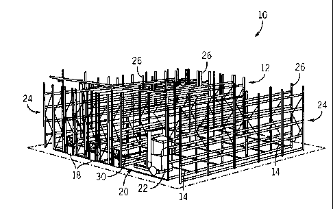
Referring now to Figs. 1 and 1A, a mobile industrial rack system 10 is
comprised of a series of industrial racks 12 that are movable along a series
of spaced and
parallel rails 14. The industrial racks 12 are arranged in pairs so as to form
multiple back-to-
back configurations 16, with each back-to-back configuration 16 having a
forward rack 12a
and a rearward rack 12b, and being movable as a single unit. Each back-to-back
configuration 16 is associated with a control interface 18 that controls
movement of the
4
CA 02818758 2013-06-12
industrial racks 12 along the rails 14. Either through an input directly to
the control interface
1 8 or using suitable remote controls, the back-to-back configurations 16 can
be translated
along the rails 14 to move the location of an aisle 20 between adjacent back-
to-back
configurations 16, based on the industrial rack 12 that is to be accessed. In
a preferred
embodiment, the racks 12 are moved such that aisle 20 is sufficiently wide to
accommodate a
forklift 22. One skilled in the art will appreciate that if the forward rack
12a of a back-to-back
configuration 16 is to be accessed, the industrial racks 12 are moved such
that aisle 20 is
formed immediately forward of the forward rack 12a. On the other hand, if the
rearward rack
12b of the back-to-back configuration 16 is to be accessed, the industrial
racks 12 are moved
such that aisle 20 is formed immediately rearward of the rearward rack 12b.
Additionally, in a preferred embodiment, the mobile industrial rack system 10
may include a pair of stationary industrial racks 24 that bookend the movable
industrial racks
12, as shown in Fig. 1A. The stationary industrial racks 24 are aligned with
rails 14 but do
not translate along the rails 14. One skilled in the art will appreciate that
stationary industrial
racks 24 may be mounted proximate a wall (not shown) such that access to the
racks 24 is
available only if an aisle 20 is formed between a stationary rack 24 and a
movable rack 12 or,
alternately, each stationary rack 24 may be positioned such that an aisle (not
shown) is formed
between the stationary rack 24 and the wall.
Each industrial rack 12, 24 is comprised of vertical posts 26 of generally
equal
height connected to one another by a series of bars 28. In a preferred
implementation, each
industrial rack 12, 24 will include multiple sets of bars 28 that are
connected to the vertical
posts 26 such that multiple storage bays 30 are defined for each industrial
rack 12, 24. In a
preferred embodiment, each storage bay 30 is adapted to support a load such as
at least one
pallet (not shown).
Referring now to Fig. 2, each movable industrial rack 12 is translated along
rail
14 by a carriage that includes a series of carriage drive units 32, each of
which includes a
drive roller 34 and a driven roller 36. Each carriage drive unit 32 further
includes a pair of
support members 38 of length generally equal to the depth of the industrial
rack that it
supports. The support members 38 couple to two vertical posts 26 using a
suitable
connection. In addition to being joined indirectly through the coupling of the
vertical posts
CA 02818758 2013-06-12
26, the support members are interconnected by a drive roller axle 40 and a
driven roller axle
42. In a manner as is known, the carriage drive units 32 are secured together
by a suitable
frame structure the supports the industrial racks 12.
As further shown in Fig. 3, the drive roller 34 includes a drive wheel 44 that
is
caused to rotate about axle 40 by a belt and gear assembly 46. The belt and
gear assembly 46
includes a gear 48 centered about axle 40 and designed to rotate in either a
clockwise or
counterclockwise direction based on the translational direction of belt 50.
Alternately, belt 50
may be a chain. The belt 50 is trained about gear 48 and a drive gear 52 that
is centered about
drive shaft 54. When drive shaft 54 is caused to rotate, the drive gear 52
also rotates and
translates belt 50 about its trained path thereby causing drive wheel 44 to
rotate and thus
travel along rail 14. The drive shaft 54 is caused to rotate by a motor
assembly 56.
Referring back to Fig. 2, the driven roller 36 includes a driven wheel 58
that, in
a preferred embodiment, is not forcibly driven like drive wheel 44 of the
drive roller. In this
regard, driven wheel 58 is not directly caused to rotate, but will only rotate
when the carriage
drive unit 32 as a whole is caused to move by rotation of drive wheel 44.
Referring now to Figs. 2 and 4-6, rail 14 includes a base plate 60 that, in a
preferred embodiment, is anchored to the floor 62 using suitable anchors 64,
such as concrete
screws. In this embodiment, the rail 14 is surface mounted to the floor 62;
although it is
contemplated that rail 14 could be recessed mounted. In a preferred
embodiment, the upper
surface of the base plate 60 is shaped to define a pair of end sections 66 and
a center section
68. A pair of channels 70 are defined between end sections 66 and the center
section 68. The
channels 70 are designed to mirror the tread pattern of wheels 44, 58. More
particularly, each
wheel 44, 58 has a tread pattern 72, 74, respectively, defined by a centered
recess 76, 78,
respectively, formed between a pair of flanges 80, 82, respectively. The
flanges 80, 82 are
designed to ride along the channel 70 and the centered recesses 76, 78 are
designed to ride
along the center section 68 of rail 14.
As further shown in Fig. 4, the driven wheel 58 is coupled in a known way to a
hub 84 defining a central bore 86 through which axle 42 extends between the
pair of support
members 38. Axle spacers 87 position the driven wheel 58 between the pair of
support
members 38. As further shown in Fig. 5, the drive wheel 44 also has a hub 88
defining a
6
CA 02818758 2013-06-12
central bore 90 through which axle 40 extends between support members 38. Gear
48 is
supported by a gear plate 92 that is mounted to an exterior surface of drive
wheel 44 and is
designed to rotate around axle 40. Axle spacers 93 position the drive wheel 44
between
support members 38. Gear 48 further includes a pair of pins 94 that
interconnect the gear 48
and the drive wheel 44. The interconnection couples the gear 48 and the drive
wheel 44 to
one another so that rotation of the gear 48 by belt 50 causes rotation of the
drive wheel 44.
Referring now to Figs. 7-8, a flue spacer 96 according to one aspect of the
invention is shown interconnecting the forward rack 12a and the rearward rack
12b of a back-
to-back configuration 16. The flue spacer 96 includes a forward mounting plate
98a and a
rearward mounting plate 98b. The forward mounting plate 98a is coupled to a
vertical post 26
of the forward rack 12a and the rearward mounting plate 98b is coupled to a
vertical post 26
of the rearward rack 12b using suitable connectors (not shown), such as bolts.
Each mounting
plate 98a, 98b carries an extension member 100a, 100b, respectively, that is
sized such that
extension member 100a at least partially shrouds extension member 100b. In
this regard,
extension member 100a is designed to slide within extension member 100b.
Extension member 100a has a vertical slot 102 whereas extension member
100b has a horizontal slot 104. When the extension members 100a, 100b are
properly
aligned, a portion of the vertical slot 102 is aligned with horizontal slot
104 such that bolt 106
may extend through the vertical slot 102 and the horizontal slot 104 along an
axis that is
transverse to both the vertical slot 102 and the horizontal slot 104.
More particularly, extension member 100a includes a top plate 108 and a pair
of downwardly extending side plates 110; only one of which is visible in the
figures. The
vertical slot 102 is formed in one of the side plates 100 whereas a second
vertical slot (not
shown) aligned with vertical slot 102 is formed in the other of the side
plates. Extension
member 100b also includes a top plate 112 and a pair of downwardly extending
side plates
114, with each side plate 114 having a horizontal slot 104 formed therein.
Bolt 106 has a
length sufficient to extend through the horizontal slot 104 of each side plate
114.
In operation, the flue spacer 96 is designed to allow relative movement of the
industrial racks 12a, 12b when the industrial racks 12a, 12b are moved along
an uneven
surface. Specifically, as the forward rack 12a is moved in the forward
direction and
7
CA 02818758 2013-06-12
encounters an area of rail 14 that is on a non-level portion of the underlying
floor, the forward
rack 12a will experience an angular displacement relative to the rearward rack
12b. The flue
spacer 96 allows the forward rack 12a to play in two different directions
relative to the
rearward rack 12b as a result of the change in floor incline. More
particularly, the vertical slot
102 allows the forward rack 12a to ride upward relative to the rearward rack
12b as a result of
the change in floor incline. Thus, extension member 100a will move upward
relative to bolt
106.
Additionally, the flue spacer 96 will permit the forward rack 12a to slide
forward or rearward relative to the rearward spacer 12b. More particularly,
the extension
member 100a may slide along the top plate 112 and side plates 114 of extension
member
100b without the extensions members 100a, 100b disconnecting from one another.
The bolt
106 extending through the vertical and horizontal slots 102, 104 maintains the
interconnection
of the extension members 100a, 100b and thus racks 12a, 12b but allows a
limited
displacement or play of the racks 12a, 12b relative to one another. The ends
of the slots 102,
104 define the range of relative vertical and horizontal movement between the
racks 12a, 12b,
to accommodate a desired degree of angular displacement between the racks 12a,
12b.
Flue spacers such as 96 are provided on selected ones of posts 26 and at one
or
more locations along the height of the posts 26, according to the length and
height of the
industrial racks 12, in order to securely maintain the racks together when the
racks 12 are
moved together in a back-to-back configuration 16.
Referring now to Figs. 9 and 9A, the racks 12a, 12b of a back-to-back
configuration 16 are also joined by a carriage spacer 116 that includes a pair
of braces 118
arranged parallel to another with a pin connection 120 interconnected
therebetween. The
carriage spacer 116 is mounted in a conventional manner to carriage drive unit
32 of the
forward industrial rack 12a and the carriage drive unit 32 of the rearward
rack 12b. As
illustrated in Fig. 9, mounting brackets 122 are interconnected between the
carriage spacer
116 and the carriage drive units 32. The mounting brackets 122 include legs
124 that are
designed to mate against the lower surface of a vertical post 26 and secured
to the vertical
post 26 by inserting bolts (not shown) through holes (not shown) formed in the
vertical post
26 that are aligned with slots 126 formed in the legs 124.
8
CA 02818758 2013-06-12
Referring particularly to Fig. 9A, braces 118 are each comprised of a pair of
wall members 128, a top plate 130, and a bottom plate 132. Holes 134, which
are aligned
with one another, extend through the pair of wall members 128. The braces 118
are both
fastened in a known way to end plate 136 that is fastened to the mobile
carriage drive unit 32
of the rearward rack 12b. The carriage spacer 116 further includes a mounting
plate 138 that
is fastened in a known way to the carriage drive unit 32 of the forward rack
12a. The
mounting plate 138 has a pair of projections 140 each of which is defined by a
narrow plate
142 having a hole 144 formed therethrough. When assembled, the mounting plate
138 is
positioned relative to the braces 118 such that holes 134 and 144 are aligned.
Pivot pin 146 is
then inserted through both sets of holes 134, 144 and retained therethrough by
ring 147. The
pivot pin 146 provides a pivot against which the racks 12a, 12b may move
relative to another
when the racks 12a, 12b are being moved along rail 14.
In a preferred embodiment, holes 144 are slightly larger and more elongated
than holes 134. Thus, holes 144 effectively form slots in which the pivot pin
146 may move
vertically relative to the mounting plate 138 when the racks 12a, 12b are
being moved in the
rearward direction. Alternately, holes 144 allow the mounting plate 138 to
move relative to
the pivot pin 146 when the racks 12a, 12b are being moved in the forward
direction. Thus,
when variations in the incline of the floor are encountered, the carriage
spacer 116 will
maintain connection of the back-to-back racks 12a, 12b but permit limited
displacement so as
to reduce the impact of the unleveled floor.
In a preferred embodiment, each back-to-back configuration 16 will have
multiple carriage drive units 32 to translate the racks along rails 14 As
described above, each
carriage includes a drive wheel and a driven or follower wheel; although, it
is contemplated
that each wheel may be motor driven. Each motor driven wheel is driven
independently by a
dedicated motor; however, in a preferred embodiment, the operation of each
motor is
synchronized so that the motors for a given back-to-back configuration 16
operate at
approximately the same speed.
As shown in Fig. 10, each motor assembly 56 includes a drive shaft 148 driven
by a motor 150. Each motor 150 includes an encoder 152 that counts rotations
of the motor
150. The encoder counts are provided to an encoder interface 154 that outputs
the encoder
9
CA 02818758 2015-04-15
counts to control board 156. The control board 156 associated with each motor
assembly 56
includes software that causes a processor 158 to compare the encoder count
value of each
motor 150 and then provide command signals to the motor 150 to synchronize
motor speed
for all the motors 150 for a given rack 12 or back-to-back configuration 16.
More
particularly, each processor 158 compares the encoder count for each motor and
adjusts
operation of its associated motor 150 such that the encoder count differential
between motors
approaches zero. The encoder count values are communicated between processors
158
through a high-speed link 160. Thus, while the motors 150 are controlled
independently, their
operation is synchronized to reduce racking or skewing during translation of
the racks 12 over
an unleveled surface.
While the present invention has been described with respect to industrial
racks,
it is understood that the invention may also be used in other mobile rack
systems where it is
desirable to account for, rather than replace or modify, an unleveled floor.
Additionally, while
the invention has been described with respect to an industrial rack system
having flue spacers,
carriage spacers, and a synchronous motor control, it is understood that these
structural
components operate independent of another and thus a given rack system may
incorporate less
than all these features to account for an unleveled floor. Also, it is
understood that the rack
system may include other features not specifically described herein to provide
additional rack
stability such as load distribution sensors, tip rails, and the like.
The scope of the claims should not be limited by particular embodiments set
forth herein, but should be construed in a manner consistent with the
specification as a whole.