Note: Descriptions are shown in the official language in which they were submitted.
'CA 02818928 2013-05-23
METHOD FOR PRODUCTION OF JOINT MEMBER FOR CARBON FIBER
COMPOSITE MATERIAL
Technical Field
The present invention relates to a method for producing a joint member between
a carbon fiber composite material and a metal.
Background Art
A carbon fiber composite material has high specific strength and specific
rigidity
and is valued as an extremely excellent material. However, in joining a
conventional
carbon fiber composite material using a thermosetting resin as a matrix to a
different kind
of a member, particularly a metal, those are jointed using bolt/nut, a rivet
or the like that
are mechanical joints, or an adhesive. The mechanical joint by bolt/nut or the
like
generally involves increase in weight. Particularly, there is a concern that
in a composite
material, stress concentrates in a joint point, and in the worst case fracture
continuously
proceeds starting from the first stress concentrated point. In the joint using
an adhesive,
an adhesive layer having a certain thickness must be generally secured in
order to
secure strength.
Particularly, in the case of joining a large-sized member, a
considerably amount of the adhesive is required. As a result, there is a
concern in great
increase in weight of the member obtained, and additionally, there is a defect
that its
strength is not always sufficient with only the adhesive. Furthermore, because
much
time is required until the adhesive develops generally practical strength, an
aging step
must be taken into consideration. On the other hand, in a carbon fiber
composite
material using a thermoplastic resin as a matrix (hereinafter sometimes
referred to as a
"thermoplastic carbon fiber composite material"), materials are joined to each
other by
1
CA 02818928 2013-05-23
welding in a range that resins are compatible, and joint strength comparable
to the matrix
resin can be expected. However, there are many cases that the joint to a metal
by
welding is difficult even in the thermoplastic carbon fiber composite
material.
To weld the thermoplastic carbon fiber composite material to a metal, it is
required that the thermoplastic resin itself used as a matrix can weld to a
metal. Patent
Document 1 describes that the reason that a metal and a resin can be joined by
welding
is due to an anchor effect by injection-molding a resin to an aluminum
material having
finely porous surface. Patent Documents 2 and 3 describe that a resin and a
metal are
joined by applying a treatment to a metal surface.
Furthermore, Patent Document 4 describes a joining method by providing an
intermediate resin layer having an affinity with both a thermosetting carbon
fiber
composite material and a metal.
Patent Document 1: JP-A-2003-103563
Patent Document 2: JP-B-5-51671
Patent Document 3: W02009/157445 pamphlet
Patent Document 4: JP-A-2006-297927
Disclosure of the Invention
Problems that the Invention is to Solve
An object of the present invention is to provide a method for producing a
joint
member between a carbon fiber composite material containing a resin as a
matrix and a
metal, and particularly to provide a method for producing a joint member
between a
carbon fiber composite material containing a thermoplastic resin as a matrix
and a metal,
characterized in that joint and molding can be conducted simultaneously.
The advantage of a thermoplastic carbon fiber composite material is that its
2
'CA 02818928 2013-05-23
shape easily changes by applying heat, and due to this, injection- or press-
molding can
be conducted in an extremely short period of time as compared with a
thermosetting
carbon fiber composite material. Therefore, if a carbon fiber composite
material
containing a thermoplastic resin as a matrix is used and the joint can be
extremely easily
performed by thermo-compression bonding in a mold simultaneously with the
molding or
just after the molding, a joint body with a metal material can be obtained
extremely
efficiently. However, even though the thermoplastic carbon fiber composite
material is
tried to join to a metal by the joining method of a thermoplastic resin and a
metal as
described in Patent Documents 2 and 3, the thermoplastic carbon fiber
composite
material is that a thermoplastic resin is in a state of "soaking into" a
carbon fiber bundle.
Thus, the resin is not always homogeneously present on the surface of the
material, and
in some cases, a "deficient" portion of a resin is present. Therefore, there
was a
concern that sufficient joint strength is not developed and joint strength
shows great
variations. Furthermore, the carbon fiber causes a so-called electrolytic
corrosion to a
metal. Therefore, when the carbon fiber has been brought into contact with a
metal in a
portion where the resin has been deficient, the contact has caused the
corrosion of a
metal.
Means for Solving the Problems
As a result of intensive investigations on the joint between a thermoplastic
carbon fiber composite material and a metal, the present inventors have found
that the
metal and the thermoplastic carbon fiber composite material can be joined
strongly and
stably by forming a layer containing a triazine thiol derivative on the
surface of the metal,
providing a thermoplastic resin layer between the layer containing the
triazine thiol
derivative and the thermoplastic carbon fiber composite material, and melting
the
thermoplastic resin layer, thereby joining the metal to the carbon fiber
composite material,
3
CA 02818928 2013-05-23
and have reached the present invention. The constitution of the present
invention is
described below.
1. A method for producing a joint member between a carbon fiber composite
material containing a thermoplastic resin as a matrix and a metal, the method
comprising
forming a layer containing a triazine thiol derivative on a surface of the
metal, providing a
thermoplastic resin layer between the layer containing the triazine thiol
derivative and the
carbon fiber composite material, and melting the thermoplastic resin layer to
join the
metal to the carbon fiber composite material.
2. The method for producing a joint member as described in item 1 above,
wherein
the metal is heated to be joined by means of electromagnetic induction.
3. The method for producing a joint member as described in any one of items
1 to 2
above, wherein the thermoplastic resin layer has a thickness of from 51.1m to
5 mm.
4. The method for producing a joint member as described in any one of items
1 to 3
above, wherein an element constituting the metal mainly comprises iron or
aluminum.
5. The method for producing a joint member as described in any one of items
1 to 4
above, wherein an amount of the thermoplastic resin present in the carbon
fiber
composite material is from 50 to 1,000 parts by weight per 100 parts by weight
of the
carbon fiber.
6. A joint member comprising a thermoplastic carbon fiber composite
material and
a metal that are joined in joint strength of 5 MPa or more, obtained by the
production
method of any one of items 1 to 5 above.
7. A method for producing a metal composite molded body comprising a carbon
fiber composite material containing a thermoplastic resin as a matrix and a
metal, that are
joined, the method comprising forming a layer containing a triazine thiol
derivative on a
surface of the metal, and melting a thermoplastic layer provided between the
layer
4
CA 02818928 2013-05-23
containing the triazine thiol derivative and the carbon fiber composite
material to
simultaneously or continuously conduct joint between the metal and the carbon
fiber
composite material, and molding thereof.
Advantages of the Invention
According to the present invention, a thermoplastic carbon fiber composite
material and a metal can be joined strongly and stably by a simplified method.
Furthermore, by joining the thermoplastic carbon fiber composite material to
the metal
through a thermoplastic resin, electrolytic corrosion caused by carbon fiber
can be
simultaneously prevented. Additionally, a joint member between the carbon
fiber
composite material and the metal can be obtained in a short period of time and
in less
number of steps by simultaneously or continuously conducting joint and molding
steps.
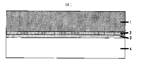
Brief Description of the Drawings
Fig. 1 is a schematic view showing one embodiment of the joint member of the
present invention.
Fig. 2 is a schematic view showing the shape of the molded body obtained in
Example 5.
Fig. 3 is a schematic view showing the shape of the metal composite molded
body obtained in Example 5. In the drawing, a circular SPCC sheet was shown by
an
oblique line.
Description of Reference Numerals
1 Thermoplastic carbon fiber composite material
2 Thermoplastic resin layer
3 Layer containing a triazine thiol derivative
CA 02818928 2013-05-23
4 Metal
Best Mode for Carrying out the Invention
The present invention relates to a method for producing a joint member between
a carbon fiber composite material containing a thermoplastic resin as a matrix
and a
metal. One embodiment of the joint member of the present invention is shown in
Fig. 1,
and an embodiment of the present invention is described below.
[Thermoplastic carbon fiber composite material]
The thermoplastic carbon fiber composite material used in the present
invention
is a material containing a thermoplastic resin as a matrix, and a carbon
fiber. The
thermoplastic carbon fiber composite material preferably contains the
thermoplastic resin
in an amount of from 50 to 1,000 parts by weight per 100 parts by weight of
the carbon
fiber. More preferably, the amount of the thermoplastic resin is from 50 to
400 parts by
weight per 100 parts by weight of the carbon fiber. Still more preferably, the
amount of
the thermoplastic resin is from 50 to 100 parts by weight per 100 parts by
weight of the
carbon fiber. Where the amount of the thermoplastic resin is less than 50
parts by
weight per 100 parts by weight of the carbon fiber, dry carbon fiber in the
composite
material may be increased. On the other hand, where the amount exceeds 1,000
parts
by weight, the amount of the carbon fiber is too small, and the carbon fiber
may become
inappropriate as a structural material.
Examples of the thermoplastic resin include polyamide, polycarbonate,
polyoxymethylene, polyphenylene sulfide, polyphenylene ether, modified
polyphenylene
ether, polyethylene terephthalate, polybutylene terephthalate, polyethylene
naphthalate,
polyethylene, polypropylene, polystyrene, polymethyl methacrylate, AS resin
and ABS
resin. Particularly, from the balance between costs and properties, at least
one selected
6
CA 02818928 2013-05-23
from the group consisting of polyamide, polypropylene, polycarbonate and
polyphenylene
sulfide is preferred. As the polyamide (sometimes abbreviated as PA, and
sometimes
called nylon), at least one selected from the group consisting of PA6 (called
polycaproamide or polycaprolactam, and more accurately, poly e-caprolactam),
PA26
(polyethylene adipamide), PA46 (polytetramethylene
adipamide), PA66
(polyhexamethylene adipamide), PA69 (polyhexamethylene azepamide), PA610
(polyhexamethylene sebacamide), PA611 (polyhexamethylene undecamide), PA612
(polyhexamethylene dodecamide), PA11 (polyundecane amide), PA12 (polydodecane
amide), PA1212 (polydodecamethylene dodecamide), PA6T (polyhexamethylene
terephthalamide), PA6I (polyhexamethylene isophthalamide), PA912
(polynonamethylene dodecamide), PA1012 (polydecamethylene dodecamide), PA9T
(polynonamethylene terephthalamide), PA9I (polynonamethylene isophthalamide),
PA1 OT (polydecamethylene terephthalamide), PA1 01
(polydecamethylene
isophthalamide), PA11 T (polyundecamethylene
terephthalamide), PA11I
(polyundecamethylene isophthalamide), PA12T (polydodecamethylene
terephtalamide),
PA12I (polydodecamethylene isophthalamide) and polyamide MXD6 (polymetaxylene
adipamide) is preferred.
The form of the carbon fiber in the thermoplastic carbon fiber composite
material
is not particularly limited. A woven fabric comprising continuous fibers or a
fabric having
fibers arranged in one direction may be used. In the case of arranging the
fibers in one
direction, the fiber layers are stacked in a multilayer by changing the
direction of layers.
For example, the layers can be alternately stacked. Furthermore, it is
preferred that the
stacking face is arranged symmetrically to a thickness direction.
In the thermoplastic carbon fiber composite material, discontinuous carbon
fibers
may be dispersed and arranged so as to overlap. In this case, a fiber length
is
7
CA 02818928 2013-05-23
preferably from 5 to 100 mm. In the case of the discontinuous carbon fibers,
the carbon
fibers may be present in the state of carbon fiber bundle in the composite
material, and it
is preferred that the carbon fiber bundle and single fiber are intermingled.
It is also
preferred that the discontinuous carbon fibers are arranged two-dimensional-
randomly in
the composite material.
As the thermoplastic carbon fiber composite material, long-fiber pellets, that
is,
pellets obtained by a step of adjusting a molten resin to a viscosity,
impregnating carbon
fiber of continuous fiber with the molten resin, and then cutting may be used,
and molded
into a shape by an injection molding machine.
[Metal]
Examples of the metal used in the present invention specifically include
metals
such as iron, stainless steel, aluminum, copper, brass, nickel and zinc. It is
preferred
that the element constituting the metal mainly comprises iron or aluminum. The
term
"mainly" used herein means 90% by weight or more. Particularly, iron such as
SS steel,
SPCC steel or high tensile steel, stainless steel such as SUS304 or 316,
aluminum of
#1000-700, and its alloy are preferably used.
The shape of the metal to be joined is not particularly limited, and can be
appropriately selected according to the desired joint member.
[Layer containing triazine thiol derivative]
The layer containing a triazine thiol derivative is formed on the surface to
be
joined of a metal, and is used for joining. The layer containing a triazine
thiol derivative
is not required to be formed on the entire surface to be joined of the metal,
and its
thickness is not particularly limited so long as adhesiveness is secured.
Preferred
examples of the triazine thiol derivative include dehydrated silanol-
containing triazine
thiol derivative to which chemical bonding to a metal can be expected, and an
8
CA 02818928 2013-05-23
alkoxysilane-containing triazine thiol derivative.
The alkoxysilane-containing triazine thiol derivative is preferably at least
one
selected from the group consisting of compounds represented by the following
general
formulae (1) and (2):
R1 NR2SiX3_nYn
N N (1)
HSLNSM
NR3SiX3_nYn
N N (2)
HS )N )SM
(In the above general formulae (1) and (2), R1 is any one of H¨, CH3¨, C2H5¨,
CH2=CHCH2¨, C4H9¨, C6H5¨ and C6H13¨. R2 is any one of ¨CH2CH2¨, ¨CH2CH2CH2¨,
¨CH2CH2CH2CH2CH2CH2¨, ¨CH2CH2SCH2CH2¨ and ¨CH2CH2NHCH2CH2CH2¨. R3 is
¨(CH2CH2)2CHOCONHCH2CH2CH2¨ or ¨(CH2CH2)2N¨CH2CH2CH2¨, and in this case, N
and R3 form a cyclic structure.
In the above general formulae (1) and (2), X is any one of CH3¨, C2H5¨, n-
C3F17¨,
i-C3H7¨, n-C4H9¨, i-C4H9¨, t-C4H9¨ and C6H5¨, Y is any one of CH30¨, C2H50¨, n-
C3H70¨,
i-C3H70¨, n-C4H90¨, t-C4H90¨ and C6H50¨, n is any one of 1, 2 and 3, and
M
is ¨H or an alkali metal.), and
the following general formula (3):
9
CA 02818928 2013-05-23
HS N SM'
NN
(3)
R4
CONHCjHziSi(Z)3
(In the above general formula (3), R4 is S , O , NHCH2C6H40¨, ¨NHC6H40¨,
¨NHC6H3(CI)0¨, ¨NHCH2C6H3(NO2)0¨, ¨NHC6H3(NO2)0¨, ¨NHC6H3(CN)0¨,
¨NHC6H2(NO2)20¨, ¨NHC6H3(COOCH3)0¨, ¨NHC10H60¨, ¨NHC101-15(NO2)0¨,
¨NHC10H4(NO2)20¨, ¨NHC6H4S-, ¨NHC6H3(CI)S¨,
¨NHCH2C6H3(NO2)S¨,
¨NHC6H3(NO2)S¨, ¨NHC6H3(CN)S¨, ¨NHC6H2(NO2)2S¨, ¨NHC6H3(COOCH3)S¨,
¨NHC10H6S¨, ¨NHC101-15(NO2)S¨ and ¨NHC10H4(NO2)2S¨, M' is ¨H or an alkali
metal, Z is
an alkoxy group, and preferably an alkoxy group having from 1 to 4 carbon
atoms, and j is
an integer of from 1 to 6.).
In the above general formulae (1) to (3), the alkali metal is at least one
selected
from the group consisting of lithium, sodium, potassium, rubidium and cesium.
Preferred example of the triazine thiol derivative used in the present
invention
specifically includes the following monosodium
triethoxysilylpropylaminotriazine thiol that
is an alkoxysilane-containing triazine thiol derivative showing excellent
effect.
HS 0C2H5
Si¨OC H
\ 2 5
OC2H5
NaS
Preferred examples of the method for forming the layer containing a triazine
thiol
derivative includes the method described in W02009/157445, pamphlet.
Specifically, a
method of dipping in alkoxysilane-containing triazine thiol, water and ethanol
solution,
CA 02818928 2013-05-23
pulling out, subjecting to heat treatment, completing reaction and drying is
exemplified.
The layer containing a triazine thiol derivative may contain substances other
than the
triazine derivative in a range that the object of the present invention is not
impaired.
[Metal compound layer]
A metal compound layer such as a hydroxide, a carbonate, a phosphate or a
sulfate may be formed between the layer containing a triazine thiol derivative
and the
metal, and the formation can expect further enhancement in joint strength,
which is
preferred. The method for forming the metal compound layer preferably includes
the
method described in W02009/157445, and specifically includes a method of
dipping in
an acid such as hydrochloric acid, sulfuric acid or phosphoric acid.
[Thermoplastic resin layer]
The present invention is characterized in that the thermoplastic resin layer
is
provided between the thermoplastic carbon fiber composite material and the
layer
containing a triazine thiol derivative provided on the metal, and the
thermoplastic resin
layer is melted, thereby joining the metal to the carbon fiber composite
material. The
thermoplastic resin layer is not required to be provided on the entire surface
to be joined,
so long as adhesiveness is secured. The thermoplastic resin layer is arranged
in a film
form, a woven fabric form, a non-woven fabric form or a powder form, and heat
and
pressure are applied to melt the thermoplastic resin to such an extent that
fibers of the
thermoplastic carbon fiber composite material can be impregnated with the
thermoplastic
resin, thereby joining the metal to the carbon fiber composite material.
The thermoplastic resin constituting the thermoplastic resin layer is
preferably a
resin that is compatible with the matrix resin of the thermoplastic carbon
fiber composite
material, and preferably includes the same resin as the matrix resin
constituting the
thermoplastic carbon fiber composite material. More preferably, the
thermoplastic resin
11
CA 02818928 2013-05-23
constituting the thermoplastic resin layer and the thermoplastic resin
constituting the
thermoplastic carbon fiber composite material are the same kind of resins. The
preferred examples of the thermoplastic resin constituting the thermoplastic
resin layer
include the same resins as described in the thermoplastic resin constituting
the
thermoplastic carbon fiber composite material.
The thermoplastic resin layer has a thickness of preferably from 5 pan to 5
mm,
more preferably from 20 ptm to 4 mm, and still more preferably from 40 pim to
3 mm.
Where the thickness of the resin layer is less than 5 m, a resin necessary
for welding
becomes insufficient, and there is a case that sufficient strength is not
obtained. Where
the thickness of the resin layer exceeds 5 mm, moment acts on a joint surface
when
shear load is applied to both, and strength may be decreased as a whole. By
providing
the resin layer in a thickness of 5 1.1m or more, sufficient resin can be
supplied when
welding, and the carbon fiber can be prevented from contacting with the metal.
As a
result, prevention of electrolytic corrosion can be expected, which is
preferred.
[Welding method]
In the method for producing a joint member of the present invention, the
thermoplastic resin layer is provided between the layer containing a triazine
thiol
derivative on the surface of the metal and the carbon fiber composite
material, and the
thermoplastic resin layer is melted, thereby joining the metal firmly to the
carbon fiber
composite material.
The method for melting a thermoplastic resin layer is preferably a method by
heating and pressurizing. The heating method is preferably heat transfer,
radiation, and
the like by an external heater. The method for heating a metal to be joined by
electromagnetic induction is extremely preferred for the reason that a joint
surface to a
resin can be directly heated. The timing of heating the metal is preferably to
match
12
CA 02818928 2013-05-23
when molding the heated resin, from the standpoint that joint strength is most
increased.
However, on the step, it is possible to heat the metal after molding, and
again
pressurizing to join.
The heating temperature is preferably from a melting temperature of the
thermoplastic resin constituting the thermoplastic resin layer to a
decomposition
temperature thereof, and more preferably from (melting temperature + 15 C) to
(decomposition temperature ¨ 30 C). The pressuring conditions are that a
pressure of
from 0.01 to 2 MPa, preferably from 0.02 to 1.5 MPa, and still more preferably
from 0.05
to 1 MPa, is applied to the welding surface. Where the pressure is less than
0.01 MPa,
good joint strength may not be obtained, and there is a case that the
composite material
springs back during heating, and the shape cannot be maintained, thereby
decreasing
material strength. On the other hand, where the pressure exceeds 2 MPa,
pressurized
part crushes, thereby the shape may be difficult to maintain the shape or
material
strength may be decreased.
The thermoplastic resin layer provided between the layer containing a triazine
thiol derivative and the carbon fiber composite material may be formed by
previously
adhering the resin layer to any one side of those. In the case of forming the
thermoplastic resin layer on any one side, the thermoplastic resin layer is
preferably
provided by adhesion at the side of the metal layer having the layer
containing a triazine
thiol derivative formed on the surface thereof. Furthermore, the joint member
can be
produced by stacking the thermoplastic resin layer and the carbon fiber
composite
material on the metal layer having the layer containing a triazine thiol
derivative attached
thereto, and simultaneously thermocompression-bonding the whole.
The temperature of the step of forming the thermoplastic resin layer is more
preferably from (melting temperature of thermoplastic resin + 15 C) to
(decomposition
13
CA 02818928 2013-05-23
temperature thereof ¨ 30 C). The thermoplastic resin layer can be arranged by
using
the thermoplastic resin in a film form, a woven form, a non-woven form or a
sheet form
and thermocompression-bonding the same, or adhering the molten resin in small
thickness by injection molding.
The temperature of the metal when contacting the molten thermoplastic resin is
preferably from (melting temperature of thermoplastic resin + 15 C) to
(decomposition
temperature thereof ¨ 30 C). Where the temperature of the metal is lower than
the
range, there is a case that the resin is difficult to adapt to the surface. On
the other hand,
where the temperature exceeds the range, decomposition of the resin may
proceed.
The time for maintaining the temperature is better to be short as possible if
the time for
substantially joining the metal to the thermoplastic carbon fiber composite
material can be
secured. The joint strength between the thermoplastic resin layer and the
metal is that
affinity by the layer containing a triazine thiol derivative on the surface of
the metal is
important, and there is generally a concern that the layer containing a
triazine thiol
derivative modifies by high temperature. For this reason, high temperature in
a long
period of time is not preferred. As one example, the joint time at 275 C is
preferably 10
minutes or shorter.
[Metal composite molded body]
In the case of joining a carbon fiber composite material containing a
thermosetting resin as a matrix to a metal, it has been forced to use of an
adhesive or the
molding over a long period of time in an autoclave after inserting the metal
in a prepreg.
The present invention, however, uses the carbon fiber composite material
containing a
thermoplastic resin as a matrix, and therefore, the joining of the metal can
be conducted
simultaneously with a molding step such as pressing, or continuously. That is,
the
present invention includes a method for producing a metal composite molded
body in
14
CA 02818928 2013-05-23
=
which a carbon fiber composite material and a metal are joined, characterized
in that the
molding and the joining are simultaneously conducted in a mold.
Accordingly, the present invention also relates to a method for producing a
metal
composite molded body in which a carbon fiber composite material containing a
thermoplastic resin as a matrix and a metal are joined, characterized in that
a layer
containing a triazine thiol derivative is provided on the surface of the
metal, and a
thermoplastic resin layer provided between the layer containing a triazine
thiol derivative
and the carbon fiber composite material is melted, thereby simultaneously or
continuously conducting the joining and molding of the metal and the carbon
fiber
composite material. The molding and joining in the production of the metal
composite
molded body can be conducted in a short period of time. Therefore, the method
of the
present invention is an industrially superior method as compared with the case
of using
the conventional carbon fiber composite material containing a thermosetting
resin as a
matrix. In the method for producing a metal composite molded body of the
present
invention, the term "continuously conducting the joining and molding of the
metal and the
carbon fiber composite material" includes not only an embodiment that the
molding is
continuously conducted after joining the metal to the carbon fiber composite
material, but
also an embodiment that after molding the carbon fiber composite material into
a desired
shape, the metal is continuously joined.
[Joint member]
The joint member comprising a carbon fiber composite material and a metal that
are strongly joined is obtained. Joint strength of the joint member is 5 MPa
or more.
The joint strength can be evaluated by a tensile test, and the upper limit of
the joint
strength is substantially about 50 MPa. The joint member and the metal
composite
molded body, obtained in the present invention are suitably used as a
structural member
=
CA 02818928 2013-05-23
requiring strength. Example of the structural member includes a part
constituting a
moving vehicle such an automobile. The number of a joint part of the joint
member is
not limited, and can be optionally selected depending on single lap or double
lap, and
depending on joint environment. The double lap is that the area becomes two
times,
and therefore, the joint strength becomes two times.
Example
The present invention is specifically described below on the basis of
examples,
but the invention is not limited to those.
Conditions of the measurement of physical properties and the evaluation in
each
example and comparative example are as follows.
1) Joint strength
Five joint members as described in each example were prepared, and a value of
a tensile strength obtained by conducting a tensile test in a rate of 1 mm/min
by a
universal tester INSTRON 5587 was defined as a joint strength of the joint
member.
[Reference Example 1]
Production of carbon fiber composite material of continuous fiber 00 and 90
alternate
stacking materials
Continuous carbon fibers (TENAX STS40-24KS (fiber diameter: 7 m, tensile
strength: 4,000 MPa), manufactured by Toho Tenax Co., Ltd.) were stacked into
64 layers
alternately in fiber directions of 0 and 900 while stacking nylon 6 films
(UNITIKA
EMBLEM ON, 25 tm thick) (carbon fiber: 64 layers, nylon: 65 layers), and the
resulting
assembly was compressed under heating at 260 C under a pressure of 2 MPa for
20
minutes. Thus, a carbon fiber composite material having 0 and 90 alternate
fibers,
symmetric stacking, volume ratio of carbon fibers: 47% (content of carbon
fibers in mass
16
CA 02818928 2013-05-23
basis: 57%) and a thickness of 2 mm was prepared.
[Reference Example 2]
Production of flat plate carbon fiber composite material comprising random
material
Carbon fibers (TENAX STS40, average fiber diameter: 7 lam, manufactured by
Toho Tenax Co., Ltd.) cut in an average fiber length of 16 mm were randomly
arranged to
made a fiber sheet having an average density is 540 g/m2, and were sandwiched
among
cloths of UNITIKA KE 435-POG (nylon 6). The resulting assembly was pressed at
260 C under 2.5 MPa to prepare a flat plate carbon fiber composite material
having a
carbon fiber volume ratio of 35% (carbon fiber content on the basis of mass:
45%) and a
thickness of 2 mm.
[Metal surface treatment]
A metal sheet having a length of 100 mm, a width of 25 mm and a thickness of
1.6 mm was degreased in a sodium hydroxide aqueous solution having a
concentration
of 15.0 g/L at a temperature of 60 C for 60 seconds. The metal sheet was then
washed
with water for 60 seconds and dried in an oven at 80 C for 30 minutes. The
metal sheet
was dipped in a phosphoric acid aqueous solution (90% or more of components
other
than water is phosphoric acid) having a concentration of from 30 to 50 g/L for
300
seconds, and then washed with hot water (60 C) for 60 seconds and washed with
water
for 60 seconds, to form a metal compound coating film comprising a metal
phosphate and
a hydroxide as main components on the surface of the metal sheet. The metal
sheet
having the metal compound coating film was dipped in an ethanol/water (volume
ratio:
95/5) of monosodium triethoxysilylpropylaminotriazine thiol having a
concentration of 0.7
g/L at room temperature for 30 minutes. The metal sheet was heat-treated in an
oven at
160 C for 10 minutes. The metal sheet was dipped in an acetone solution
containing
N,N'-m-phenylenedimaleimide having a concentration of 1.0 g/L and dicumyl
peroxide
17
CA 02818928 2013-05-23
having a concentration of 2 g/L at room temperature for 10 minutes, and heat-
treated in
an oven at 150 C for 10 minutes. An ethanol solution of dicumyl peroxide
having a
concentration of 2 g/L was sprayed to the entire surface of the metal sheet at
room
temperature, and air-dried to provide a triazine thiol derivative layer over
the entire
surface of the metal sheet.
[Example 1]
The metal surface treatment described above was applied to both surfaces of
SPCC (cold-reduced carbon steel sheet) having a length of 100 mm, a width of
25 mm
and a thickness of 1.6 mm, and two nylon 6 films (UNITIKA EMBLEM ON, 25 vim
thick,
melting point: 225 C) were provided on both surfaces thereof. The SPCC sheet
was
heated to 250 C by electromagnetic induction heating, and then immediately
cooled to
ordinary temperature. The nylon films were melted and closely attached, and
then
solidified to form a layer of nylon 6 on the SPCC surface. The carbon fiber
composite
material obtained in Reference Example 2 was cut into a length of 100 mm and a
width of
25 mm, stacked on the SPCC sheet having the nylon layer in a range of 25 mm x
25 mm
by single lap, and pressurized under heating at 250 C under 0.2 MPa for 5
minutes using
a mold to prepare a joint member between the thermoplastic carbon fiber
composite
material and the SPCC sheet. Five joint members were prepared, and subjected
to a
tensile test in a rate of 1 mm/min by a universal tester INSTRON 5587. As a
result, the
average value of the joint strength was 12 MPa.
[Example 2]
The metal surface treatment described above was applied to both surfaces of a
590 MPa category high tensile steel having a length of 100 mm, a width of 25
mm and a
thickness of 1.6 mm, two nylon 6 films (UNITILA EMBLEM ON, 25 vtm thick) were
provided on both surfaces thereof. The high tensile steel was heated to 250 C
by
18
CA 02818928 2013-05-23
electromagnetic induction heating, and then immediately cooled to ordinary
temperature.
The nylon films were melted, closely attached and solidified to form a layer
of nylon 6 on
the high tensile steel surface. The flat sheet comprising the random material
obtained in
Reference Example 2 was cut into a length of 100 mm and a width of 25 mm,
stacked on
the high tensile steel having the nylon layer in a range of 25 mm x 25 mm by
single lap,
the thermoplastic carbon fiber composite material was heated at 250 C, and the
high
tensile steel was heated to 140 C, followed by pressuring under heating under
0.2 MPa
for 1 minute using a mold. Subsequently, the high tensile steel in the
material lapped
was heated to 250 C by electromagnetic induction heating, and pressurized
under
heating under 0.2 MPa for 1 minute to prepare a joint member between the
thermoplastic
carbon fiber composite material and the high tensile steel. Five joint members
were
prepared, and subjected to a tensile test in a rate of 1 mm/min by a universal
tester
INSTRON 5587. As a result, the average value of the joint strength was 17 MPa.
[Example 3]
Two nylon 6 films (UNITIKA EMBLEM ON, 25 p.m thick) were provided on both
surfaces of the SPCC sheet having a length of 100 mm, a width of 25 mm and a
thickness of 1.6 mm, which was subjected to the metal surface treatement in
the same
steps as in Example 1. The carbon fiber composite material obtained in
Reference
Example 1 was cut into a length of 100 mm and a width of 25 mm, was heated to
250 C,
stacked on the SPCC sheet having the nylon 6 layer in a range of 25 mm x 25 mm
by
single lap, and pressurized under heating together with the SPCC sheet
previously
heated to 250 C by electromagnetic induction heating under a pressure of 0.2
MPa for 5
minutes using a mold to prepare a joint member between the thermoplastic
carbon fiber
composite material and the SPCC. Five joint members were prepared, and
subjected to
a tensile test in a rate of 1 mm/min by a universal tester INSTRON 5587. As a
result, the
19
CA 02818928 2013-05-23
average value of the joint strength was 7.4 MPa.
[Example 4]
A layer of nylon 6 was formed on the surface of an aluminum sheet in the same
manner as in Example 1, except that 5052 aluminum sheet having a thickness of
1 mm
was used in place of the SPCC sheet. The flat sheet comprising a random
material
obtained in Reference Example 2 was cut into a length of 100 mm and a width of
25 mm,
and stacked on the aluminum steel having the nylon layer in a range of 25 mm x
25 mm
by single lap, followed by pressuring under heating at 250 C under a pressure
of 0.2 MPa
for 5 minutes using a mold, thereby preparing a joint member between the
thermoplastic
carbon fiber composite material and the 5052 aluminum sheet. Five joint
members were
prepared, and subjected to a tensile test in a rate of 1 mm/min by a universal
tester
INSTRON 5587. As a result, the aluminum sheet part was broken. Calculating
from
breaking strength of the aluminum sheet, it was seen that the joint strength
was 7.1 MPa
or more.
[Comparative Example 1]
The same operation as in Example 1 was conducted, except that the nylon 6
layer was not provided on the SPCC sheet having a length of 100 mm, a width of
25 mm
and a thickness of 1.6 having been subjected to metal surface treatment, and
in place of
the carbon fiber composite material obtained in Reference Example 2, a nylon 6
piece
having the same size was joined. However, as a result that it was tried to
measure joint
strength of the joint member obtained, the nylon 6 piece was broken off.
[Example 5]
The carbon fiber composite material obtained in Reference Example 1 was
heated to 250 C, and pressed under a pressure of 20 MPa using a mold at 140 C
to
obtain a nearly U-shaped molded body having a length of 1,200 mm, a width of
150 mm
CA 02818928 2013-05-23
and a height of 50 mm as shown in Fig. 2. Five holes having a diameter of 10
mm were
formed in the molded body as shown in Fig. 2. The SPCC sheet having a hole
having a
diameter of 10 mm at the center thereof, and having a diameter of 100 mm and a
thickness of 1.6 mm having been subjected to the metal surface treatment in
the same
steps as in Example 1 was placed on each of five holes through two nylon 6
films
(UNITILA EMBLEM ON, 25 vtm thick) having the same size. The resulting assembly
was heated to 250 C by electromagnetic induction heating, and the SPCC sheet
was
pressurized until reaching about 100 C by a force of 20 kgf (196N), thereby
joining to the
molded body. Thus, a metal composite molded body was obtained. The metal
composite molded body can be used as a part of a seat rail, and its shape is
shown in Fig.
3.
Industrial Applicability
The joint member of the present invention has excellent joint strength, and
can
be used in various uses such as a part constituting a moving vehicle such as
an
automobile.
21