Note: Descriptions are shown in the official language in which they were submitted.
CA 02819086 2013-06-13
LOAD-BAR ASSEMBLY HAVING ACTUATABLE LATCH ASSEMBLY
[0001] TECHNICAL FIELD
[0002] Aspects are generally related to (and not limited to) a load-bar
assembly,
including (and not litnited to) a latch assetnbly and a latch actuator.
[0003] BACKGROUND
[0004] Load securing, also known as cargo securing, is the securing of
cargo for
transportation. The European Commission Transportation Department has
estimated that
up to 25% of accidents involving trucks can be attributable to inadequate
cargo securing.
Cargo that is improperly secured can cause severe accidents and lead to the
loss of cargo,
the loss of lives, the loss of vehicles, or cause environmental hazards.
[0005] There are many different ways and materials available to stabilize
and secure
cargo in vehicles and/or intennodal containers. Blocking and bracing is a load
secureinent method utilizing lumber and metal bars to reduce or inhibit front
to rear
shifting of freight/cargo. Plastic forms are also used. Depending on the type
of load and
the particular vehicle, large bolts and nails may be used. These may be on the
load itself
or on wood blocks used to brace the load. Dunnage for securing cargo has
included scrap
wood to fill voids in cargo, wooden boards forming cribs, blocking and
bracing, and
modern mechanical, spring-loaded post-and-socket systems. Dunnage segregates
cargo
into the hold and prevents shifting of the cargo in response; to ship or
vehicle motions.
Strapping is used to create a transportable unit. Types of strapping include
steel,
polyester, polypropylene, nylon, paper, and composites. The type of strap used
depends
upon the requireinents, for example, strength, elasticity, ability to
withstand various
environments, ease of use, safety, and cost. All types of tensioned strapping,
particularly
steel, need to be handled carefully because of potential injury. Lashing is
the securing of
cargo for transportation with the goal of minimizing shifting. Items used for
lashing
include ropes, cables, wires, chains, strapping, and nets. These items are
anchored to the
1
HON-ZLB/CDA
CA 02819086 2013-06-13
container and tensioned against the cargo. Lashing may be used for devices
attached to
the top ()Teach corner of a container. Whereas strapping and lashing is often
used to
secure odd-shaped cargo such as machinery, structures, and vehicles, dunnage
bags are
mostly used for homogeneous shaped cargo such as food and beverage products,
electronics and appliances and roll paper. Often, strapping/lashing and
dunnage bags are
used in combination to secure chemical products. Dunnage bags, also known as
air bags,
were introduced years ago as a convenient, last and cost-effective alternative
to secure
and stabilize cargo in sea-containers, closed railcars, trucks and (ocean
going-) vessels.
The purpose of dunnage bags is often misunderstood when they are considered as
a void
filler only to prevent lateral movement of cargo. When properly applied,
however,
dunnage bags form a 3-dimensional bulkhead of the cargo itself preventing both
lateral
and longitudinal movement. Heavy loads are sometimes secured to vehicles with
tie
down straps, heavy-duty strapping, or tensioned chains.
[0006] SUMMARY
[0007] I, the inventor, have researched at least one problem associated
with known load
bars configured to secure loads in a cargo hold of a vehicle. After much
study, I believe I
have arrived at an understanding of at least one problem and at least one
solution, which
are stated below (in no particular order of importance).
[0008] Known load bars (also known as decking bars), nylon load straps, and
jack bars
are mechanisms configured to restrain loads in a truck during transit. An E-
track system
is a track system mounted to the inside walls of thc back of the truck. There
can be
separate rows of the E-track on each of the sidewalls (on opposite facing
walls). The
known load bar is configured to connect to (interface with) the E-track and to
secure the
load from shifting and falling during transit. The load bar is configured to
be lengthwise
adjustable.
[0009] Known load bars are difficult to remove from the e-track for the
case where the
load bar is under some load pressure. In order to remove the known load bar,
the operator
has to use a non-ergo friendly body position and use an amount of force that
exceeds
ergonomic guidelines that may inadvertently result in operator injury. When
the known
2
HON-ZLB/CDA
CA 02819086 2013-06-13
load bars are jammed and cannot be easily removed (if at all), the operator
may use pry
bars to dislodge the load bar from the E-track, and this may result in
operator injury along
with wasted time/effort. As well, since there are no handles on the known load
bars, this
makes them difficult to maneuver, and the operator may have to use a high
amount of
pinch pressure to carry the known load bars to a storage rack.
[00010] Storage straps may not work for a trailer loaded wall to wall with
cargo (a load),
as during transit the load may bump against mechanisms of the straps that are
interfaced
with the E-track (wall track, bracket), and this situation may inadvertently
cause
unwanted interference or failure of the storage straps.
[00011] The jack bar (also known as a cargo bar) does not use the E-Track;
the jack bar
has rubber pads that are pushed outward to contact the sidewalls of the truck.
The jack
bar uses friction to hold itself and the load in place. The jack bar is not
functional with
heavier loads or loads that are susceptible to shifting.
[00012] In order to mitigate at least some of the above issues, in
accordance with an aspect
of my work, I (the inventor) have developed an apparatus that includes a load-
bar
assembly configured to latchably selectively extend between spaced-apart
opposed walls
once the load-bar assembly is positioned to do just so. The apparatus also
includes a latch
actuator configured to actuatably urge latchable operation of the load-bar
assembly froin
a latch-extended position, in which the load-bar assembly is inadvertently
jammed, to a
latch-retracted position, in which the latch assembly becomes unjammed.
[00013] In order to mitigate at least some of the above issues, ,in
accordance with an aspect
of my work, I (the inventor) have developed an apparatus for a vehicle having
spaced-
apart opposed walls of a cargo-holding zone. The apparatus comprises a load-
bar
assembly configured to extend between the spaced-apart opposed walls once the
load-bar
assembly is positioned to do just so. The load-bar assembly has a latch
assembly
configured to selectively latch with a respective instance of the spaced-apart
opposed
walls once the latch assembly is positioned to do just so. A latch actuator is
fixedly
mounted to the load-bar assembly 102, and is configured to actuatably urge the
latch
assembly to selectively move from a latch-extended position (in which the
latch assembly
is inadvertently jammed with the spaced-apart opposed walls) to a latch-
retracted 'position
(in which the latch assembly becomes unjammed from the spaced-apart opposed
walls so
3
HON-ZLB/CDA
CA 02819086 2015-12-08
that the load-bar assembly is removable from the spaced-apart opposed walls
once the
latch assembly is unjammed).
[00014] In order to mitigate at least some of the above issues, in accordance
with an aspect
of my work, I (the inventor) have developed an apparatus for a vehicle. The
vehicle has
opposed wall brackets facing each other. The opposed wall brackets are mounted
to
spaced-apart opposed walls of a cargo-holding zone of the vehicle. The opposed
wall
brackets define instances of a track groove. The apparatus further comprises a
load-bar
assembly configured to extend between the opposed wall brackets once the load-
bar
assembly is positioned to do just so. The apparatus further comprises a latch
assembly
configured to: (A) operatively mount the load-bar assembly; (B) biasedly move
toward an
instance of the opposed wall brackets once the latch assembly is positioned to
do just so;
and (C) securely latch with the instance of the opposed wall brackets once the
latch
assembly is positioned to do just so. A latch actuator is configured to
operatively couple
with the latch assembly, and to actuatably urge the latch assembly to
selectively move
from a latch-extended position to a latch-retracted position.The load bar
assembly
includes a first longitudinal inner passage in communication with the latch
assembly,
and a second lateral passage in communication with the first longitudinal
inner passage,
the latch actuator includes an elongated member extending from the latch
assembly along
the first longitudinal inner passage; and a lever pivotally mounted relative
to the load bar
assembly and extending through the second lateral passage and operatively
connected to
the elongated member, the lever being adjustably movable in such a way that
the
elongated member urges the latch assembly to move from the latch-extended
position to
the latch-retracted position.
[00015] In order to mitigate at least some of the above issues, in accordance
with another
aspect of my work, I (the inventor) have developed an apparatus for the
vehicle. The
apparatus comprises a load-bar assembly configured to extend between the
opposed wall
brackets. The load-bar assembly has a first end and also has a second end
spaced apart
from the first end. Each of the first end and the second end face a respective
instance of
the opposed wall brackets once the load-bar assembly is positioned to do just
so. The
apparatus further comprises a latch assembly configured to: (A) operatively
mount at any
one of the first end and the second end of the load-bar assembly; (B) biasedly
move along
4
HON-ZLIVCDA
CA 02819086 2015-05-28
a longitudinal axis of the load-bar assembly toward an instance of the opposed
wall
brackets once the latch assembly is positioned to do just so; and (C) securely
latch with
the instance of the opposed wall brackets once the latch assembly is
positioned to do just
so. The apparatus further comprises a latch actuator configured to: (A)
operatively mount
the load-bar assembly; and (B) actuatably urge the latch assembly to
selectively move
from a latch-extended position to a latch-retracted position.
[00016] In order to mitigate at least some of the above issues, in accordance
with yet
another aspect of my work, I (the inventor) have developed a method of
operating an
apparatus for a vehicle having spaced-apart opposed walls of a cargo-holding
zone. The
method comprises: (A) extending a load-bar assembly between the spaced-apart
opposed
walls once the load-bar assembly is positioned to do just so, and the load-bar
assembly
having a latch assembly configured to selectively latch with a respective
instance of the
spaced-apart opposed walls once the latch assembly is positioned to do just
so; and (B)
actuatably urge a latch assembly to selectively move from a latch-extended
position, in
which the latch assembly is inadvertently jammed with the spaced-apart opposed
walls,
to a latch-retracted position, in which the latch assembly becomes unjarnmed
from the
spaced-apart opposed walls so that the load-bar assembly is removable from the
spaced-
apart opposed walls once the latch assembly is unjammed.
[00017] In order to mitigate at least some of the above issues, in accordance
with yet
another aspect of my work, I (the inventor) have developed a method of
operating an
apparatus. The method comprises: (A) extending a load-bar assembly between the
opposed wall brackets once the load-bar assembly is positioned to do just so,
and a latch
assembly is operatively mounted to the load-bar assembly; (B) biasedly moving
the latch
assembly toward an instance of the opposed wall brackets once the latch
assembly is
positioned to do just so; (C) securely latching the latch assembly with the
instance of the
opposed wall brackets once the latch assembly is positioned to do just so, and
a latch
actuator is operatively coupled to the latch assembly; and (D) actuatably
urging the latch
assembly to selectively move from a latch-extended position to a latch-
retracted position.
[00018] In accordance with other aspects of my work, I (the inventor) have
developed and
provided other aspects as provided in the claims.
HON-ZLB/CDA
CA 02819086 2015-05-28
[00019] Generally speaking, the aspects of the present invention may be
configured to
reduce (eliminate) safety and/or ergonomic concerns associated with removing
known
load bars from the cargo area of a transport truck,
[00020] Other aspects and features of the non-limiting embodiments may now
become
apparent to those skilled in the art upon review of the following detailed
description of
the non-limiting embodiments with the accompanying drawings.
[00021] BRIEF DESCRIPTION OF DRAWINGS
[00022] The non-limiting embodiments may be more fully appreciated by
reference to the
following detailed description of the non-limiting embodiments when taken in
conjunction with the accompanying drawings, in which:
[00023] FIGS. IA and 1B depict a side view and a top view, respectively, of a
schematic
example of an apparatus.
[00024] FIGS. 2A and 2B depict side views of another schematic example of the
apparatus
of FIGS. IA and 1B.
[00025] FIGS. 3A, 3B and 3C depict a side view and top views, respectively, of
schematic
examples of the apparatus of FIGS. lA and 1B.
[00026] FIGS. 4A and 4B depict side views of yet another schematic example of
the
apparatus of FIGS. lA and 1B.
[00027] FIGS. 5A and 5B depict side views of yet another schematic example of
the
apparatus of FIGS. IA and I B.
[00028] FIGS. 6A and 6B depict side views of yet another schematic example of
the
apparatus of FIGS. IA and 1B.
[00029] FIG. 7 depicts a side view of yet another schematic example of the
apparatus of
FIGS. lA and 1B.
[00030] The drawings are not necessarily to scale and may be illustrated by
phantom lines,
diagrammatic representations and fragmentary views. In certain instances,
details not
necessary for an understanding of the embodiments (and/or details that render
other
details difficult to perceive) may have been omitted.
6
HON-ZLB/CDA
CA 02819086 2015-05-28
[00031] DETAILED DESCRIPTION OF EXEMPLARY EMBODIMENTS
[00032} The following detailed description is merely exemplary in nature and
is not
intended to limit the described embodiments or the application and uses of the
described
embodiments. As used herein, the word "exemplary" or "illustrative" means
"serving as
an example, instance, or illustration." Any implementation described herein as
"exemplary" or "illustrative" is not necessarily to be construed as preferred
or
advantageous over other implementations. All of the implementations described
below
are exemplary implementations provided to enable persons skilled in the art to
make or
use the embodiments of the disclosure and are not intended to limit the scope
of the
disclosure, which is defined by the claims. For purposes of description
herein, the terms
"upper," "lower," "left," "rear," "right," "front," "vertical," "horizontal,"
and derivatives
thereof shall relate to the examples as oriented in the drawings. Furthermore,
there is no
intention to be bound by any expressed or implied theory presented in the
preceding
technical field, background, brief summary or the following detailed
description. It is also
to be understood that the specific devices and processes illustrated in the
attached
drawings, and described in the following specification, are simply exemplary
embodiments (examples), aspects and/or concepts defined in the appended
claims.
Hence, specific dimensions and other physical characteristics relating to the
embodiments
disclosed herein are not to be considered as limiting, unless the claims
expressly state
otherwise.
[00033] FIGS. IA and 1B depict a side view and a top view, respectively, of a
schematic
example of an apparatus 100.
[00034] Referring now to FIGS. 3A and 3B, the apparatus 100 is, generally
speaking, for a
vehicle 10. An example of the a vehicle 10 is a tractor trailer (and any
equivalent
thereof). The vehicle 10 has opposed wall brackets 12 facing each other. The
opposed
wall brackets 12 are mounted to spaced-apart opposed walls 14 of a cargo-
holding zone
16 of the vehicle 10. Each of the opposed wall brackets 12 defines instances
of a track
groove 18 positioned in a spaced-apart linear relationship (one instance
positioned after
the other instance) along the opposed wall brackets 12.
7
HON-ZLB/CDA
CA 02819086 2015-05-28
[00035] Referring back to FIGS, IA and 1B, the apparatus 100 includes a load-
bar
assembly 102, a stop pin 103, a latch assembly 111, a first latch-support
member 105, a
second latch-support member 107, a latch actuator 108, a lever 112, a housing-
handle
assembly 114, and a lever handle 116. The load-bar assembly 102 has a housing
assembly 101 defining a longitudinal passage. The housing assembly 101 defines
a lateral
passage in the form of a housing passageway 113 configured to accommodate, at
least in
part, extension of the latch actuator 108 so that the latch actuator 108 may
extend from
inside (that is from the longitudinal passage) of the load-bar assembly 102 to
outside of
the load-bar assembly 102. In this way, the user may have manipulative access
to the
exposed portion of the lever 112 that extends externally from the load-bar
assembly 102.
The lever 112 is operatively mounted to the load-bar assembly 102. The load-
bar
assembly 102 has a first end 126 and a second end 128 that is set apart from
the first end
126, each of which are located at opposite ends of the load-bar assembly 102.
The
definition of "operatively" means in a manner to produce an effect (such as
being
mounted so as to operate without operative interference). The housing assembly
101
includes a central portion, and also includes (at least in part) hollow
tubular members that
extend from the opposite end sections of the central portion (and as well
extend along the
longitudinal axis that extends through the load-bar assembly 102). The hollow
tubular
members may have any type of cross-sectional shape (square shaped, etc.).
[00036] 13y way of example: (A) the first latch-support member 105 may include
a
movable plunger (and any equivalent thereof), (B) the second latch-support
member 107
may include a movable plunger (and any equivalent thereof), and/or (C) the
latch
assembly 111 may include a first latch 104, and a second latch 106 spaced
apart from the
first latch 104. The first latch-support member 105 and the second latch-
support member
107 are each configured to be slidably (movably) received in the first end 126
and the
second end 128, respectively (in the hollow tubular members of the load-bar
assembly
102). The definition of "slidably received" means that an object is received
in a channel
or groove by sliding movement or action of the object.
[00037] The housing assembly 101 defines instances of a pass-through hole 132
(depicted
in FIG. 1B) positioned at the first end 126 and at the second end 128
(respectively) of the
load-bar assembly 102. The pass-through hole 132 is axially aligned through
the load-bar
8
HON-ZLB/CDA
CA 02819086 2015-05-28
assembly 102. The pass-through hole 132 is dimensioned in such a way that the
stop pin
103 may axially slide into the pass-through hole 132 (so that the stop pin 103
remains
stationary relative to the load-bar assembly 102 while the stop pin 103 is
received in the
pass-through hole.132). The first latch-support member 105 and the second
latch-support
member 107 each defines an instance of an elongated slot 130 (as depicted in
FIG. 1A)
located proximate to a respective instance of the stop pin 103. Instances of
the stop pin
103 are configured to slide into: (A) a respective instance of the pass-
through hole 132
defined by the housing assembly 101, and (B) a respective instance of the
elongated slot
130 defined by the first latch-support member 105, and (C) a respective
instance of the
elongated slot 130 defined by the second latch-support member 107. The
instances of the
stop pin 103 are configured to permit limited sliding movement of the first
latch-support
member 105 and of the second latch-support member 107 along the longitudinal
axis of
the load-bar assembly 102 (while the load-bar assembly 102 remains relatively
stationary). In this manner, the first latch-support member 105 and the second
latch-
support member 107 are slidably movable between stop limits (relative to the
load-bar
assembly 102) along the longitudinal axis extending through the load-bar
assembly 102).
[00038] For the case (not depicted) where the housing assembly 101 defines
instances of
the pass-through hole 132 that are linearly aligned along each instance of the
first end
126 and the second end 128 of the load-bar assembly 102, the stop pin 103 is
configured
to allow lengthwise adjustment of the apparatus 100 (of the load-bar assembly
102).
Relocation of the stop pin 103 allows the first latch-support member 105 and
the second
latch-support member 107 to be repositioned or relocated on the housing
assembly 101 of
the load-bar assembly 102. In this manner, a distance between the spaced-apart
opposed
walls 14 (depicted in FIG. 3B) may be accommodated depending on the particular
type of
vehicle 10 in which the apparatus 100 is to be used.
[00039] Retelling to FIGS. IA and 1B, the first latch-support member 105 and
the second
latch-support member 107 are slidably movable along the longitudinal axis
extending
through the load-bar assembly 102. The instances of the elongated slot 130
extend along
the longitudinal axis of the load-bar assembly 102. The instances of the
elongated slot
130 receive a respective instance of the stop pin 103 so that the first latch-
support
member 105 and the second latch-support member 107 are permitted to have
limited
9
HON-ZLB/CDA
CA 02819086 2015-05-28
1r
1
linear slide movement along the longitudinal axis of the load-bar assembly
102. The
instances of spring assembly 118 (not depicted in FIGS. lA and 1B but depicted
in FIGS.
2A and 2B) are mounted inside the load-bar assembly 102, and are configured to
biasedly
move the first latch-support member 105 and the second latch-support member
107
outwardly along the longitudinal axis of the pivot assembly 120 between
physical limits
or stops as a result of the stop pin 103 abutting the end sections of each
instance of the
elongated slot 130. The definition of "biasedly move" means that an object has
a
tendency or inclination or preference to move in a certain direction.
[00040] Referring to FIGS. lA and 1B, the stop pin 103 does not move relative
to the
housing assembly 101 of the load-bar assembly 102, but the first latch-support
member
105 and the second latch-support member 107 are movable (may travel) relative
to the
stop pin 103 to the extent or to the dimension of the elongated slot 130. In
this manner,
the first latch-support member 105 and the second latch-support member 107,
generally
speaking, are slidably mounted to the load-bar assembly 102 at the respective
opposite
ends of the load-bar assembly 102, and travel between the two limits or stops.
[00041] The first latch 104 of the latch actuator 108 extends (outwardly and
away) from
the first latch-support member 105 at the first end 126 along the horizontal
axis that
extends through the housing assembly 101. The second latch 106 of the latch
actuator
108 extends (outwardly and away) from the second latch-support member 107 at
the
second end 128 along the horizontal axis that extends through the housing
assembly 101.
The first latch 104 and the second latch 106 extend in (along) opposite
directions from
the load-bar assembly 102 (along the longitudinal axis of the load-bar
assembly 102).
[00042] By way of example, the latch actuator 108 includes: (A) the lever 112
operatively
mounted to the load-bar assembly 102, and (B) the lever handle 116 that
fixedly extends
from the lever 112. The definition of "fixedly extends" means an object is
fixedly
connected to another object, and extends from said another object. The lever
handle 116
is configured for user manipulation. In addition, the housing-handle assembly
114 fixedly
extends axially from the housing assembly 101 of the load-bar assembly 102 at
a position
proximate to the first end 126, and extends from an outer portion of the load-
bar
assembly 102. The apparatus 100 may be configured to provide the housing-
handle
HON-ZLB/CDA
CA 02819086 2015-05-28
assembly 114 located strategically on the load-bar assembly 102 (to be
balanced for
carrying) to reduce the effort required (by the user) to carry the apparatus
100.
[00043] According to an option, the load-bar assembly 102 is configured to
extend
between the opposed wall brackets 12 (of FIG. 3B). The load-bar assembly 102
has the
first end 126 and also has the second end 128 spaced apart from the first end
126. Each of
the first end 126 and the second end 128 faces a respective instance of the
opposed wall
brackets 12 once the load-bar assembly 102 is positioned to do just so (as
depicted in
FIG. 3B).
[00044] According to an option, the latch assembly 111 is configured to
operatively mount
at any one of the first end 126 and the second end 128 of the load-bar
assembly 102. The
latch assembly 111 is further configured to biasedly move (is spring biased)
along the
longitudinal axis of the load-bar assembly 102 toward an instance of the
opposed wall
brackets 12 once the latch assembly 111 is positioned to do just so (as
depicted in FIG.
3B). The latch assembly 111 is further configured to securely latch with
instances of the
opposed wall brackets 12 once the latch assembly 111 is positioned to do just
so (as
depicted in FIG. 3B).
[00045] According to an option, the latch actuator 108 is configured to be
operatively
mounted to the load-bar assembly 102. The latch actuator 108 is further
configured to
actuatably urge the latch assembly 111 to selectively move from a latch-
extended
position (as depicted in FIG. 2A) and a latch-retracted position (as depicted
in FIG. 2B).
The definition of "actuatably urge" means that an object is urged to operate
by way of an
actuator.
[000461 In accordance with another example, a method of operating the
apparatus 100 is
also provided. The method includes the step of extending the load-bar assembly
102
between the opposed wall brackets 12 once the load-bar assembly 102 is
positioned to do
just so (depicted in FIG. 3B). A latch assembly 111 is operatively mounted to
the load-
bar assembly 102. The method also includes the step of biasedly moving the
latch
assembly 111 toward an instance of the opposed wall brackets 12 once the latch
assembly
111 is positioned to do just so. The method also includes the step of securely
latching the
latch assembly 111 with the instance of the opposed wall brackets 12 once the
latch
assembly 111 is positioned to do just so (as depicted in FIG. 3B). A latch
actuator 108 is
HON-ZI.B/CDA
CA 02819086 2015-05-28
operatively coupled to the latch assembly 111. The method also includes the
step of
actuatably urging the latch assembly 111 to selectively move from a latch-
extended
position to a latch-retracted position.
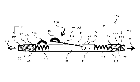
[00047] FIGS. 2A and 2B depict side views of another schematic example of the
apparatus
100 of FIGS. lA and 1B, in which there is depicted a spring assembly 118, a
pivot
assembly 120, and an elongated member 110. By way of example, the elongated n-
iernber
110 may include a cable element and/or a wire element (and any equivalent
thereof).
[00048] FIG. 2A depicts the load-bar assembly 102 in the latch-extended
position. In the
latch-extended position, the latch assembly 111 is wall-bracket engagable once
the latch
assembly 111 is positioned to do just so in such a way that the latch assembly
111
becomes securely latched to (a selected one of) the opposed wall brackets 12
(as depicted
in FIG. 3B). The first latch 104 and the second latch 106 move away from the
central
section of the load-bar assembly 102 along the longitudinal axis of the load-
bar assembly
102,
[000491 Referring to FIG. 2A, the lever 112 is biased to move (travel) along
the direction
indicated by the arrow 200 (toward the load-bar assembly 102). The instances
of the
spring assembly 118 are configured to push (move) the first latch-support
member 105
and the second latch-support member 107 along the direction indicated by the
arrow 202
and the arrow 204 (respectively) away from the central portion of the load-bar
assembly
102 and along opposite directions that extend along the longitudinal axis of
the load-bar
assembly 102. In this manner, the first latch 104 and the second latch 106 may
latch with
a respective instance of a track groove 18 of the opposed wall brackets 12 (as
depicted in
FIG. 3B).
[00050] Referring to FIG. 2B, the load-bar assembly 102 is depicted in the
latch-retracted
position. In the latch-retracted position, the latch assembly 111 is wall-
bracket dis-
engagable in such a way that the latch actuator 108 detaches the latch
assembly 111 from
(the selected one of) the opposed wall brackets 12 so that the load-bar
assembly 102 is
removable from (the selected one of) the opposed wall brackets 12 (as depicted
in FIG.
3C). The first latch 104 and the second latch 106 move toward the central
section of the
load-bar assembly 102.
12
ION-ZLB/CDA
CA 02819086 2015-05-28
[00051J Referring to FIG. 2B, as a result of the user pulling on the lever
112, the lever 112
moves (travels) along the direction indicated by the arrow 206 (away from the
load-bar
assembly 102) since the User pulls with enough force to overcome the force of
the spring
assembly 118 in such a way that the first latch-support member 105 and the
second latch-
support member 107 are moved along the direction indicated by the arrow 208
and the
arrow 210 (respectively) toward the central portion of the load-bar assembly
102. In this
manner, the first latch 104 and the second latch 106 may be removed (de-
latched) from
the respective instance of the track groove 18 of the opposed wall brackets 12
(as
. depicted in FIG. 3C). Now the apparatus 100 may be more easily removed or
relocated
(in comparison to using the known load bar) so that then the load 20 may be
removed
from the vehicle 10 (depicted in FIG. 3C).
[000521 Referring to FIG. 2B, an instance of the spring assembly 118 is
positioned
between the first latch-support member 105 and the central portion of the
housing
assembly 101 of the load-bar assembly 102. Another instance of the spring
assembly 118
is positioned between the second latch-support member 107 and the central
portion of the
housing assembly 101 of the load-bar assembly 102. The instances of the spring
assembly
118 are configured to biasedly move (urge) the first latch-support member 05
and the
second latch-support member 107 away from the central portion of the housing
assembly
101. The instances of the spring assembly 118 abut the first latch-support
member 105
and the second latch-support member 107, and abut the central section of the
load-bar
assembly 102. The instances of the spring assembly 118 extend along the
longitudinal
axis of the load-bar assembly 102.
[00053] The latch actuator 108 is configured to move the first latch-support
membex 105
and the second latch-support member 107 in such a way so as to overcome the
forces of
the spring assembly 118 thus retracting the first latch 104 and the second
latch 106
toward the central portion of the housing assembly 101 thus overcoming the
force exerted
by the spring assembly 118.
C000541 According to an option, the latch assembly 111 includes the first
latch I 04. The
elongated member 110 extends from the first latch 104 along the longitudinal
length of
the load-bar assembly 102. The lever 112 is operatively connected to the
elongated
member 110 (pivotally mounted as depicted in FIGS. 2A, 2B). The lever 112 is
13
HON-ZLIVCDA
CA 02819086 2015-05-28
operatively (pivotally) mounted to the load-bar assembly 102. The lever 112 is
adjustably
movable in such a way that the elongated member 110 urges the first latch 104
to move
from the latch-extended position to the latch-retracted position.
[00055] According to an option, the latch assembly 111 further includes the
second latch
106. The elongated member 110 extends from second latch 106 along a
longitudinal
length of the load-bar assembly 102. The lever 112 is connected to the
elongated member
110. The lever 112 is operatively mounted (pivotally) to the load-bar assembly
102. The
lever 112 is adjustably movable in such a way that the elongated member 110
urges the
second latch 106 to move from the latch-extended position to the latch-
retracted position.
[00056] According to the following options: (A) the latch assembly 111 is
configured to
pivotally mount to the load-bar assembly 102, and/or (B) the lever 112 is
configured to
pivotally mount to the load-bar assembly 102.
[00057] According to an option, the latch actuator 108 includes the elongated
member 110
and the lever 112. The elongated member 110 (such as a wire or a cable)
extends from
the latch assembly 111 along a longitudinal length of the load-bar assembly
102, The
lever 112 is connected to the elongated member 110. The lever 112 is
operatively
mounted (pivotally) to the load-bar assembly 102. The lever 112 is adjustably
movable in
such a way that the elongated member 110 urges the latch assembly 111 to move
from
the latch-extended position to the latch-retracted position.
[00058] FIGS. 3A, 3B and 3C depict a side view and top views, respectively, of
schematic
examples of the apparatus 100 of FIGS, IA and IB, The apparatus 100 is for the
vehicle
10. The vehicle 10 may have opposed wall brackets 12 that face each other. The
opposed
wall brackets 12 arc mounted to the spaced-apart opposed walls 14 of the cargo-
holding
zone 16 of the vehicle 10, The opposed wall brackets 12 each defines instances
of a track
groove 18.
[00059] During transportation, a load 20 positioned in the cargo-holding zone
16 of the
vehicle 10 may become displaced or may inadvertently move, and as a result,
the load 20
imparts a pressure 22 directed to the apparatus 100 while the apparatus 100 is
latched to
the instances of the track groove 18 of the opposed wall brackets 12. As a
result, the load-
bar assembly 102 rnay become inadvertently cleformably warped (but not
necessarily
irrevocably damaged), and thus the user may find it more difficult to rerriOVC
the load-bar
14
HON-ZLB/CDA
CA 02819086 2015-05-28
assembly 102 from the opposed wall brackets 12 (while the load-bar assembly
102
receives the pressure 22, the first latch 104 and the second latch 106 may
become
jammed). The definition of "deformably warped" means that an object may be in
the state
of being deformable (a measure of the extent to which something is deformable)
but the
object is able to recoil or spring back into its original shape after bending,
stretching, or
being compressed or receiving a pressure,
[00060] However, the features of the apparatus 100 may be used by the user to
more
conveniently remove the load-bar assembly 102 under this case. For this case,
the
apparatus 100 has a technical advantage in that after the vehicle 10 arrives
at its
destination, the user may manipulate the apparatus 100 in such a way that the
apparatus
100 allows relatively easier de-latching and removal from the opposed wall
brackets 12
(as depicted in FIG. 3C) in comparison to the way that the known load bars are
operated
and/or used.
[00061] For the case where pressure is applied to the known load bar, the user
may find it
difficult to remove the known load bar from the wall brackets; the known load
bar may
cause an ergonomic concern and/or a safety concern when they are forcibly
removed
from the wall brackets. When the known load bar becomes inadvertently stuck
(jammed)
to the wall brackets of the side walls of the vehicle 10, the user may have to
use a pry bar
to remove the known load bar, resulting in an increase in time to unload or
remove the
load from the vehicle and/or the increased possibility of unwanted injury to
the user. The
known load bars are relatively more difficult to remove in comparison to the
effort
required to remove the apparatus 100 (when the pressure 22 is applied to the
apparatus
100).
[00062] For the known load bar, testing showed that the average pressure
applied to the
known load bar may range from 113.5 pounds to 269.5 pounds thus resulting in a
required pull force (to be applied by the user) ranging from 85 pounds to 211
pounds.
[00063] In sharp contrast, the apparatus 100 was relatively easier to remove
from the
opposed wall brackets 12. Testing of the apparatus 100 showed that the average
pressure
applied to the apparatus 100 may range from 104.5 pounds to 600 pounds,
resulting in a
required pull force (to be applied by the user) ranging from 11.2 pounds to 21
pounds.
The apparatus 100 provides a distinct advantage that improves ease of removal
of the
HON-ZLB/CDA
CA 02819086 2015-05-28
load-bar assembly 102 for the case where the load-bar assembly 102 is
operatively
latched to the opposed wall brackets 12 while the load-bar assembly 102
receives the
pressure 22 from the load 20 (as depicted in FIGS. 3B and 3C). The apparatus
100 may
be configured to provide mechanical leverage configured to retract the latch
assembly
111 from the opposed wall brackets 12 (such as an E-track).
[00064] Referring to FIG. 3B and 3C, in accordance with an option, the
apparatus 100
includes a combination of the load-bar assembly 102 and the latch actuator
108. As a
minimum, the apparatus 100 may be used with the vehicle 10 that has (at the
very least in
terms of structural components) the spaced-apart opposed walls 14 of the cargo-
holding
zone 16. For example, a variation of this option includes the following set-
up: the vehicle
may or may not include the opposed wall brackets 12, if so desired, for the
case where
the opposed wall brackets 12 are replaced with an equivalent structure. For
example, the
spaced-apart opposed walls 14 are (directly or indirfectly) adapted to
accommodate the
load-bar assembly 102. The load-bar assembly 102 is configured to extend
between the
spaced-apart opposed walls 14 once the load-bar assembly 102 is positioned to
do just so.
The load-bar assembly 102 has the latch assembly 111 configured to selectively
latch
with a respective instance of the spaced-apart opposed walls 14 once the latch
assembly
111 is positioned to do just so. The latch actuator 108 is fixedly rnounted to
the load-bar
assembly 102. The latch actuator 108 is configured to actuatably urge the
latch assembly
111 to selectively move from the latch-extended position to the latch-
retracted position.
In the latch-extended position, the latch assembly 111 is inadvertently jammed
with the
spaced-apart opposed walls 14. In the latch-retracted position, the latch
assembly 111
' becomes unjammed from the spaced-apart opposed walls 14 so that the load-bar
assembly 102 is removable from the spaced-apart opposed walls 14 once the
latch
assembly 111 is unjammed (as depicted in FIG. 3C). The latch assernbly 111
becomes
unjammed from the spaced-apart opposed walls 14 while the latch assembly 111
inadvertently receives the pressure 22 from the load 20. In the latch-extended
position,
the load 20 inadvertently imparts the pressure 22 to the load-bar assembly 102
while the
latch assembly 111 is latched to the spaced-apart opposed walls 14 in such a
way that the
latch assembly 111 becomes inadvertently jammed.
16
HON-ZLB/CDA
CA 02819086 2015-05-28
[00065] It will be appreciated that in accordance with a broad concept, the
apparatus 100
includes a variation to the load-bar assembly 102 in which the load-bar
assembly 102 is
configured to latchably selectively extend between the spaced-apart opposed
walls 14
once the load-bar assembly 102 is positioned to do just so. The apparatus 100
also
includes a variartion of the latch actuator 108 in which the latch actuator
108 is
configured to actuatably urge latchable operation of the load-bar assembly 102
from a
latch-extended position, in which the load-bar assembly 102 is inadvertently
jammed, to a
latch-retracted position, in which the latch assembly 102 becomes unjammed. As
well, a
method is provided in which, general speaking, the method includes latchably
selectively
extending the load-bar assembly 102 between spaced-apart opposed walls 14 once
the
load-bar assembly 102 is positioned to do just so, and actuatably urging
latchable
operation of the load-bar assembly 102 from a latch-extended position, in
which the load-
bar assembly 102 is inadvertently jammed, to a latch-retracted position, in
which the
latch assembly 102 becomes unjarrirned.
[00066] FIGS. 4A and 4B depict side views of yet another schematic example of
the
apparatus 100 of FIGS. IA and 1B, in which the elongated member 110 connects
the
lever 112 to the first latch-support member 105. The elongated member 110 does
not
connect the lever 112 to the second latch-support member 107. The lever 112 is
actuated
so as to slidably move the first latch-support metnber 105 (and hence the
first latch 104 as
well) along the longitudinal axis of the load-bar assembly 102. Each of the
first latch-
support member 105 and the second latch-support member 107 are operatively
coupled to
respective instances of the spring assembly 118 in such a way that the first
latch-support
member 105 and the second latch-support member 107 are biasedly movable in
response
to the action of the instances of the spring assembly 118. According to this
example, the
elongated member 110 extends from the lever 112 to the first latch 104. The
second latch
106 is not connected to the lever 112. The second latch 106 remains spring
biased.
[00067] Referring to FIG. 4A, the lever 112 is biased (move or travel) along
the direction
indicated by the arrow 220 (toward the load-bar assembly 102). The instances
of the
spring assembly 118 are configured to push and move the first latch-support
member 105
and the second latch-support member 107 along the direction indicated by the
arrow 222
and the arrow 224 (respectively) away from the central portion of the load-bar
assembly
17
HON-ZLB/CDA
CA 02819086 2015-05-28
102. In this manner, the first latch 104 and the second latch 106 may latch
(couple) with
the track groove 18 of the opposed wall brackets 12 (as depicted in FIG. 3B).
[00068] Referring to FIG. 4B, as a result of the user pulling on the lever
112, the lever 112
moves (travels) along the direction indicated by the arrow 226 (pivotally away
from the
load-bar assembly 102). The user pulls with enough force to overcome the force
of the
spring assembly 118 in such a way that the first latch-support member 105 and
the
second latch-support member 107 are moved along the direction indicated by the
arrow
228 and the arrow 230 (respectively) toward the central portion of the load-
bar assembly
102. In this manner, the first latch 104 and the second latch 106 may be
removed from
the instances of the track groove 18 of the opposed wall brackets 12 (as
depicted in FIG.
3C).
[00069] kefening back to FIGS. 4A and 4B, according to an option, the latch
assembly
111 includes the first latch 104 configured to operatively mount at the first
end 126 of the
load-bar assembly 102. The first latch 104 is also configured to securely
interface with an
instance of the opposed wall brackets 12 once the first latch 104 is
positioned to do just
so. The first latch 104 is further configured to biasedly move (such as,
spring biased)
along the longitudinal axis of the load-bar assembly 102 toward the latch-
extended
position so that the first latch 104 is wall-bracket engagable once the first
latch 104 is
positioned to do just so (as depicted in FIG, 3B), In this manner, the first
latch 104
becomes securely latched to a selected instance of the opposed wall brackets
12. The first
latch 104 is further configured to move from the latch-extended position to
the latch-
retracted position in response to actuation of the latch actuator 108. In the
latch-retracted
position, the first latch 104 is wall-bracket dis-engagable in such a way that
the load-bar
assembly 102 is removable from the selected one of the opposed wall brackets
12 (as
depicted in FIG. 3C).
[00070] FIGS. 5A and 5B depict side views of yet another schematic example of
the
apparatus 100 of FIGS. lA and 1B, in which the elongated member 110 connects
the
lever 112 to the first latch-support member 105, The elongated member 110 does
not
connect the lever 112 to the second latch-support member 107. The lever 112 is
actuated
so as to (slidably) move the first latch 104 along the longitudinal axis of
the load-bar
assembly 102. The first latch-support member 105 is operatively coupled to the
spring
18
HON-ZLB/CDA
CA 02819086 2015-05-28
assembly 118 in such a way that the first latch-support member 105 is biasedly
movable
(within limits or between stops set apart from each other). The second latch-
support
member 107 is fixedly attached to an end section of the load-bar assembly 102,
and is not
movable relative to the housing assembly 101. In this way, the second latch
106 is not
spring biased but is fixedly positioned relative to the central section of the
load-bar
assembly 102.
[00071] Referring to FIG. 5A, the lever 112 is biased to move (travel) along
the direction
indicated by the arrow 240 (toward the load-bar assembly 102) since the spring
assembly
118 is configured to push and move the first latch-support member 105 along
the
direction indicated by the arrow 242 away from the central portion of the load-
bar
assembly 102. In this way, the first latch 104 may be moved into an instance
of the track
groove 18 after the second latch 106 has been moved into position in another
instance of
the track groove 18 located on the opposite instance of the opposed wall
brackets 12 (as
depicted in FIG. 3B),
[00072] Referring to FIG. 5B, as a result of the user pulling on the lever
112, the lever 112
moves (travels) along the direction indicated by the arrow 246 (away from the
load-bar
assembly 102). The user pulls with enough force to overcome the force of the
spring
assembly 118 in such a way that the first latch-support member 105 is moved
along the
direction indicated by the arrow 248 toward the central portion of the load-
bar assembly
102. In this manner, the first latch 104 is retracted from an instance of the
track groove 18
(depicted in FIG. 3C) so that the load-bar assembly 102 may then be removed;
in
response, the second latch 106 becomes removed from the track groove 18 (as
the load-
bar assembly 102 is removed; depicted at least in part in FIG. 3C).
[00073] FIGS. 6A and 6B depict side views of yet another schematic example of
the
apparatus 100 of FIGS. 1A and IB, in which the elongated member 110 connects
the
lever 112 to the first latch-support member 105, and connects the lever 112 to
the second
latch-support member 107. The lever 112 is actuated so as to (slidably) move
the first
latch 104 and the second latch 106 along the longitudinal axis of the load-bar
assembly
102. The first latch-support member 105 is operatively coupled to an instance
of the
spring assembly 118 and the second latch-support member 107 is operatively
coupled to
19
HON-ZLB/CDA
CA 02819086 2015-05-28
an instance of the spring assembly 118 in such a way that the first latch-
support member
105 and the second latch-support member 107 are biasedly (slide) movable,
[00074] FIG, 6A depicts two instances of a handle. FIG. 6B depicts three
instances of a
handle (two instances of the handle each positioned at opposite ends of the
lever 112). In
accordance with an option, the lever 112 includes a bent or angled section
(arrn) so that in
the latch extended position, the lever 112 is aligned parallel to the
longitudinal axis that
extends through the load-bar assembly 102. FIG. 6B depicts an auxiliary
extension 122
and an auxiliary handle assembly 124 (if so desired as an option). In
accordance with
several options: (A) the lever 112 includes a lever handle 116 extending from
the lover
112, and/or (B) the lever 112 further includes an auxiliary handle assembly
124 attached
to and extending from an outer portion of the load-bar assembly 102, and the
auxiliary
handle assembly 124 is spaced apart from the lever handle 116.
[00075] The latch assembly 111 includes the first latch 104 and also includes
the second
latch 106. The second latch 106 is configured to: (A) operatively mount to the
second end
128 of the load-bar assembly 102; and (B) securely interface with an instance
of the
opposed wall brackets 12 once the second latch 106 is positioned to do just
so. The
second latch 106 is configured to biasedly move (such as, spring biased) along
the
longitudinal axis of the load-bar assembly 102 toward the latch-extended
position; in this
manner, the second latch 106 is wall-bracket engagable once the second latch
106 is
positioned to do just so. In this manner, the second latch 106 becomes
securely latched to
a selected one of the opposed wall brackets 12. The second latch 106 is
configured to
move from the latch-extended position to the latch-retracted position in
response to
actuation of the latch actuator 108. In the latch-retracted position, the
second latch 106 is
wall-bracket dis-engagable in such a way that the load-bar assembly 102 is
removable
from the selected one of the opposed wall brackets 12 (as depicted in FIG.
3C).
[00076] FIG. 7 depicts a side view of yet another schematic example of the
apparatus 100
of FIGS. IA and IB. The arrow 250 indicates the direction in which the user
pulls on the
load-bar assembly 102 so that the load-bar assembly 102 is balanced in an
angled
alignment, and thus the ;apparatus 100 may be more easily stored in a vertical
position in
a vertically-aligned rack storage system (not depicted).
1-10N-ZUVCDA
CA 02819086 2015-05-28
[00077] The apparatus 100 provides the load-bar assembly 102 configured to
interface
with a wall track, such as an E-track or any equivalent thereof. The apparatus
100 may
include the latch assembly 111 (such as, the lever 112) configured to provide
a
mechanical advantage for the user of the apparatus 100 in such a way so as to
reduce user
(operator) effort required to remove the apparatus 100 from the wall track (E-
track). The
apparatus 100 may be configured to allow the user to maintain an ergonomically
friendly
body position. The lever 112 may be configured (as an option) to be pulled
along a
straight up and a smooth motion. For example, with a 16:1 mechanical advantage
provided by the lever 112, the need to use pry bars may be reduced (if not
entirely
eliminated) thereby reducing the potential of inadvertent and unwanted injury
to the user.
The apparatus 100 helps reduce the amount of effort the user requires for
removing
jammed known load bars and/or not having to find and use pry bars to remove
the
jamtned known load bars and therefore may result in efficiency (faster loading
and
unloading of cargo from the vehicle). If so desired (as an option), a carry
handle may be
used and make the apparatus 100 easier to maneuver with a reduced amount of
pinch
force to be applied by the user. The lever 112 may be mounted to a top section
of the
apparatus 100. The lever 112 may be configured to interact with a gear system
that pulls
the elongated member 110 that runs inside the apparatus 100 from the gear
system to the
latch assembly 111 positioned on at least one end or at each end section
(portion) of the
apparatus 100. The latch assembly 111 may be configured to release the
apparatus 100
from the wall track (E-track). The latch assembly 111 may be strategically
located on the
apparatus 100 to cooperate in conjunction with the handle attached to the
apparatus 100
in such a way that the operator may manipulate the load-bar assembly 102 in a
balanced
and ergo-friendly carrying position.
[00078] It may be appreciated that the assemblies and modules described above
may be
connected with each other as may be required to perform desired functions and
tasks that
are within the scope of persons of skill in the art to make such combinations
and
permutations without having to describe each and every one of them in explicit
terms.
There is no particular assembly, components, or software code that is superior
to any of
the equivalents available to the art. There is no particular mode of
practicing the
disclosed subject matter that is superior to others, so long as the functions
may be
21
HON-ZLB/CDA
CA 02819086 2015-05-28
performed. It is believed that all the crucial aspects of the disclosed
subject matter have
been provided in this document. It is understood that the scope of the present
invention is
limited to the scope provided by the independent claim(s), and it is also
understood that
the scope of the present invention is not limited to: (i) the dependent
claims, (ii) the
detailed description of the non-limiting embodiments, (iii) the summary, (iv)
the abstract,
and/or (v) description provided outside of this document (that is, outside of
the instant
application as filed, as prosecuted, and/or as granted). It is understood, for
the purposes of
this document, the phrase "includes" is equivalent to the word "comprising."
It is noted
that the foregoing has outlined the non-limiting embodiments (examples). The
description is made for particular non-limiting embodiments (examples). It is
understood
that the non-limiting embodiments are merely illustrative as examples.
22
HON-ZLEVCDA