Language selection

Search

Patent 2819196 Summary

Third-party information liability

Some of the information on this Web page has been provided by external sources. The Government of Canada is not responsible for the accuracy, reliability or currency of the information supplied by external sources. Users wishing to rely upon this information should consult directly with the source of the information. Content provided by external sources is not subject to official languages, privacy and accessibility requirements.

Claims and Abstract availability

Any discrepancies in the text and image of the Claims and Abstract are due to differing posting times. Text of the Claims and Abstract are posted:

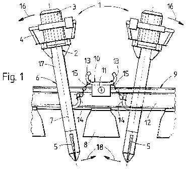
  • At the time the application is open to public inspection;
  • At the time of issue of the patent (grant).
(12) Patent Application: (11) CA 2819196
(54) English Title: METHOD OF TAMPING A TRACK
(54) French Title: PROCEDE POUR BOURRER UNE VOIE FERREE
Status: Deemed Abandoned and Beyond the Period of Reinstatement - Pending Response to Notice of Disregarded Communication
Bibliographic Data
(51) International Patent Classification (IPC):
  • E01B 27/14 (2006.01)
(72) Inventors :
  • WIDLROITHER, OTTO (Germany)
(73) Owners :
  • ROBEL BAHNBAUMASCHINEN GMBH
(71) Applicants :
  • ROBEL BAHNBAUMASCHINEN GMBH (Germany)
(74) Agent: RICHES, MCKENZIE & HERBERT LLP
(74) Associate agent:
(45) Issued:
(86) PCT Filing Date: 2011-12-21
(87) Open to Public Inspection: 2012-07-26
Availability of licence: N/A
Dedicated to the Public: N/A
(25) Language of filing: English

Patent Cooperation Treaty (PCT): Yes
(86) PCT Filing Number: PCT/EP2011/006463
(87) International Publication Number: EP2011006463
(85) National Entry: 2013-05-28

(30) Application Priority Data:
Application No. Country/Territory Date
10 2011 008 893.8 (Germany) 2011-01-19

Abstracts

English Abstract


Prior to immersion into the ballast, a hand tamper (1) for tamping a track is
detachably connected to an anchor element (10), fixed to the track (9) and
lying
opposite with regard to a tamping motion (18), by means of a fixing member
(15)
fastened to a tamper section (6) situated between a drive motor (3) and a
tamping
blade (5). Thus, an improved compaction effect can be achieved.


French Abstract

Procédé pour bourrer une voie ferrée par plongé d'une bourroir manuel (1) dans le ballast. Avant la plongée dans le ballast, le bourroir manuel (1) est raccordé de manière libérable à un élément d'ancrage (10) fixé sur la voie ferrée (9), face à la zone où s'effectue le mouvement de bourrage (18), par l'intermédiaire d'un organe de fixation (15), fixé à une partie (6) du bourroir située entre un moteur d'entraînement (3) et une pelle de bourrage (5)

Claims

Note: Claims are shown in the official language in which they were submitted.

5
Claims
1. A method of tamping a track by immersing a hand tamper into ballast,
characterized in that, prior to the immersion into the ballast, the hand
tamper (1) is
detachably connected to an anchor element (10), fixed to the track (9) and
lying
opposite with regard to a tamping motion, by means of a fixing member (15)
fastened to a tamper section (6) situated between a drive motor (3) and a
tamping
blade (5).
2. A method according to claim 1, characterized in that two hand tampers
(1),
each serving as an anchor element (10), are used for tamping, the tampers
being
connected to one another by means of the fixing member (15) and plunging into
the ballast at the same time at an opposite longitudinal side of a sleeper,
respectively, with regard to a tamping movement (18).
3. A method according to claim 1, characterized in that a rail anchor
detachably connected to the rail is used as an anchor element (10).
4. A method according to claim 3, characterized in that the anchor element
(10) is fastened at an intersection of the sleeper (8) and the rail (12).

6
5. A method according to one of claims 1 to 4, characterized in that the
fixing
member (15) is fastened to a connecting tube (17), arranged between the drive
motor (3) and a tamping blade (5), in the half of the tube situated closer to
the
tamping blade (5)

Description

Note: Descriptions are shown in the official language in which they were submitted.


= CA 02819196 2013-05-28
1
Method of tamping a track
[001] The invention relates to a method of tamping a track by means of a hand
tamper.
[002] Well-known hand tampers are gripped in an upper section comprising the
drive and have a vibrating tamping blade which is immersed into the
ballast. During the immersing operation, one tries to achieve a compacting
motion with the tamping blade in the direction towards the sleeper by
lowering the upper drive section in the direction towards the operator. The
compaction effect resulting from this, however, is unsatisfactory since the
ballast ¨ used as a kind of abutment behind the tamping blade ¨ does not
offer much resistance due to the vibrations.
[003] It is the object of the present invention to provide a method of the
type
mentioned at the beginning with which it is possible to achieve an
improved ballast compaction.
[004] According to the invention, this object is achieved with a method of the
specified kind in that, prior to the immersion into the ballast, the hand
tamper is detachably connected to an anchor element, fixed to the track
and lying opposite with regard to a tamping motion, by means of a fixing
member fastened to a tamper section situated between a drive motor and
a tamping blade.
[005] As a result of this temporary connection to the track, a non-
displaceable
abutment is created so that the downward motion of the upper section of

= CA 02819196 2013-05-28
2
the hand tamper causes a forced countermotion of the tamping blade in
the direction towards the sleeper. With this, the ballast is positively
displaced underneath the sleeper and compacted.
[006] Additional advantages of the invention become apparent from the
dependent claims and the drawing description.
[007] The invention will be described in more detail below with reference to
embodiments represented in the drawing in which Fig. 1 shows a view ¨ in
the longitudinal direction of the sleeper ¨ of two hand tampers, Fig. 2
shows a top view and Fig. 3 a simplified representation of a further variant
of the invention.
[008] Hand tampers 1, shown in Figs. 1 to 3, each have a drive motor 3,
arranged in an upper section 2, and handles 4. A central tamper portion 6
provided between the drive motor 3 and a tamping blade 5 is configured as
a connecting tube 17, having a longitudinal direction 7, in which an
eccentric shaft (not shown) is set in rotation.
[009] Located above a sleeper 8, to be tamped, of a track 9 is an anchor
element
in the shape of a rail anchor which is detachably connected to a rail 12
by means of a quick fastener 11 and has hooks 13. A fixing member 15 in
the shape of a chain or rope, for example, is fastened to the connecting
tube 17 on a hook 14 in the half of the tube lying closer to the tamping
blade 5.

CA 02819196 2013-05-28
3
[010] To execute the tamping method, the hook 14 is connected by means of the
fixing member 15 to a hook 13 of the anchor element 10 fixed to the track.
In order to achieve an optimal compaction effect, the handle 4 together
with the drive motor 3 is moved in a working direction 16 towards the
operator. Due to the connection of the central tamper section 6 to the
anchor element 10, this produces a forced tamping motion 18 of the
tamping blade 5 in the direction towards the adjacent sleeper 8.
[011] Further optimisation of the procedure of tamping the track 9 can be
achieved by synchronously employing two hand tampers 1 positioned
opposite one another ¨ with regard to the sleeper 8 to be tamped ¨ and
each connected to the anchor element 10. As indicated in dash-and-dot
lines in Fig. 2, it is also possible, by using four hand tampers 1 each
attached to the anchor element 10, to carry out synchronous tamping
motions for tamping the sleeper 8.
[012] After the ballast has been sufficiently compacted, the fixing member 15
is
detached from the anchor element 10. After attaching the anchor element
above the succeeding sleeper, the above-described tamping method is
repeated. It is also possible, of course, to fasten the anchor element 10
directly to the sleeper. Moreover, one could also use, for example, a rail
clip or the like, connecting the rail 12 to the sleeper 8, as an anchor
element for fastening the fixing member 15 to the track 9.

CA 02819196 2013-05-28
.=
4
[013] For carrying out the method according to the application, it would
alternatively also be possible to directly connect to one another by means
of the fixing member 15 only the hooks 14, serving as anchor element 10,
of two hand tampers 1 lying opposite one another, (see Fig. 3). For
achieving the best possible ballast compaction, the movement of the two
hand tampers 1 in the working direction 16 should be carried out largely
synchronously.

Representative Drawing
A single figure which represents the drawing illustrating the invention.
Administrative Status

2024-08-01:As part of the Next Generation Patents (NGP) transition, the Canadian Patents Database (CPD) now contains a more detailed Event History, which replicates the Event Log of our new back-office solution.

Please note that "Inactive:" events refers to events no longer in use in our new back-office solution.

For a clearer understanding of the status of the application/patent presented on this page, the site Disclaimer , as well as the definitions for Patent , Event History , Maintenance Fee  and Payment History  should be consulted.

Event History

Description Date
Application Not Reinstated by Deadline 2014-12-23
Time Limit for Reversal Expired 2014-12-23
Deemed Abandoned - Failure to Respond to Maintenance Fee Notice 2013-12-23
Inactive: Cover page published 2013-08-29
Inactive: Notice - National entry - No RFE 2013-07-05
Inactive: IPC assigned 2013-07-04
Inactive: First IPC assigned 2013-07-04
Application Received - PCT 2013-07-04
National Entry Requirements Determined Compliant 2013-05-28
Application Published (Open to Public Inspection) 2012-07-26

Abandonment History

Abandonment Date Reason Reinstatement Date
2013-12-23

Fee History

Fee Type Anniversary Year Due Date Paid Date
Basic national fee - standard 2013-05-28
Owners on Record

Note: Records showing the ownership history in alphabetical order.

Current Owners on Record
ROBEL BAHNBAUMASCHINEN GMBH
Past Owners on Record
OTTO WIDLROITHER
Past Owners that do not appear in the "Owners on Record" listing will appear in other documentation within the application.
Documents

To view selected files, please enter reCAPTCHA code :


To view images, click a link in the Document Description column (Temporarily unavailable). To download the documents, select one or more checkboxes in the first column and then click the "Download Selected in PDF format (Zip Archive)" or the "Download Selected as Single PDF" button.

List of published and non-published patent-specific documents on the CPD .

If you have any difficulty accessing content, you can call the Client Service Centre at 1-866-997-1936 or send them an e-mail at CIPO Client Service Centre.

({010=All Documents, 020=As Filed, 030=As Open to Public Inspection, 040=At Issuance, 050=Examination, 060=Incoming Correspondence, 070=Miscellaneous, 080=Outgoing Correspondence, 090=Payment})


Document
Description 
Date
(yyyy-mm-dd) 
Number of pages   Size of Image (KB) 
Description 2013-05-27 4 116
Drawings 2013-05-27 1 39
Claims 2013-05-27 2 34
Abstract 2013-05-27 1 11
Abstract 2013-08-21 1 11
Representative drawing 2013-08-28 1 20
Notice of National Entry 2013-07-04 1 193
Reminder of maintenance fee due 2013-08-21 1 112
Courtesy - Abandonment Letter (Maintenance Fee) 2014-02-16 1 172
PCT 2013-05-27 5 190