Note: Descriptions are shown in the official language in which they were submitted.
CA 02819325 2013-06-26
IN THE UNUED STATES PATENT AND TRADEMARK OFFICE
Utility Patent Application (Provisional)
Use of latching relays in signal switching
Thermtest Inc Employees:
Dale Hume, James Kozlowski
SPECIFICATION
CROSS-REFERENCE TO RELATED APPLICATIONS
Not Applicable
STATEMENT REGARDING FEDERALLY SPONSORED RESEARCH OR DEVELOPMENT
Not Applicable
REFERENCE TO SEQUENCE LISTING, A TABLE, OR A COMPUTER PROGRAM LISTING
COMPACT DISK APPENDIX
Not Applicable
BACKGROUND OF THE INVENTION
The present invention is in the technical field of signal measurement. More
particularly, the present
invention is in the technical field of signal switching
While other signal switching devices exist, Latching relays have not been used
to keep signal
integrity.
SUMMARY OF THE INVENTION
The present invention is a device for switching signals from multiple sources
to a single
testing or measuring device using latching relays.
BRIEF DESCRIPTION OF THE DRAWINGS
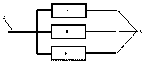
Fig. 1 is an example of a latching relay switch
CA 02819325 2013-06-26
DETAILED DESCRIPTION OF THE INVENTION
The present invention is a device for switching signals from multiple sources
to a single testing or
measuring device using latching relays. Standard relays can have a large
effect on small highly
accurate signals causing inaccurate test data. The use of latching relays
removes the always-on coil
and heat generation present in standard relays, resulting in a cleaner more
accurate signal for
testing or measuring.
Referring now to the invention in more detail, in Fig. 1 there is shown an
example switch, A is the
signal (wire(s), PCB trace(s), or other signal transfer method) going to the
testing or measuring
device, B is any number of latching relays and C is the signal (wire(s), PCB
trace(s), or other signal
transfer method) going to the testing or measuring point/sensor.
In more detail, still referring to the invention of Fig. 1 a signal that needs
to be tested or measured
enters into the system through point C and one of the relays(B) are switched
on to allow the signal
to pass through to point A where it will connect to the testing or measuring
device.
The signal switch as shown in Fig. 1 could include any number of latching
relays, as required, and
be constructed on a PCB, or simply with wires or screw terminals or one of the
many other
methods of connecting electrical components.
The advantages of the present invention include, a cleaner more reliable
signal allowing for a better
test or measurement.
While the foregoing written description of the invention enables one of
ordinary skill to make and
use what is considered presently to be the best mode thereof, those of
ordinary skill will understand
and appreciate the existence of variations, combinations, and equivalents of
the specific
embodiment, method, and examples herein. The invention should therefore not be
limited by the
above described embodiment, method, and examples, but by all embodiments and
methods within
the scope and spirit of the invention.
