Note: Descriptions are shown in the official language in which they were submitted.
CA 02819819 2013-06-03
- 1 -
DESCRIPTION
STRUCTURE FOR SIDE PORTION OF VEHICLE BODY
Technical Field
The present invention relates to a vehicular side structure including a roof
side rail (rail assembly) extending in a front-and-rear direction of a vehicle
body
and defining an upper portion of the structure, a roof rail (arch assembly)
having an end located on the rail assembly, and a roof panel supported by the
arch assembly.
Background Art
A vehicular side structure of type above is well known, as disclosed in JP-A-
2003-118634. The side structure disclosed in JP-A-2003-118634 includes a rail
assembly including an inner member (an inner panel) defining an inner wall of
the rail assembly. The rail assembly also includes an outer member (a pillar
reinforcement member) overlying an exterior surface of a portion of the inner
member to provide the rail assembly with a closed cross-section. The side
structure also includes an arch assembly extending laterally of a vehicle and
connected to the rail assembly. A roof panel is disposed above the arch
assembly to cover the arch assembly.
The arch assembly includes upper and lower members which define a
closed cross-section. The arch assembly of closed cross-section is spot welded
to the rail assembly of closed cross-section to rigidify the vehicular side
structure.
As for the side structure disclosed in JP-A-2003-118634, since the outer
member of the rail assembly overlies the portion of the inner member of the
rail
assembly, a boundary between the portion of the inner member and the
remaining portion of the inner member defines a boundary between the outer
member and the inner member. Thus, to provide the roof panel atop the inner
CA 02819819 2013-06-03
- 2 -
and outer members of the rail assembly, a flange of the roof panel is welded
to
both of the inner and outer members astride the boundary between the inner
and outer members.
However, due to molding or fabrication tolerances of the inner and outer
members, it is difficult to accurately form the boundary between the inner and
outer members in assembling the inner and outer members together. It is thus
difficult to accurately position the roof panel relative to the inner and
outer
members during a process of welding the flange of the roof panel to both of
the
inner and outer members astride the boundary therebetween.
As for the side structure disclosed in JP-A-2003-118634, further, the arch
assembly of closed cross-section, the rail assembly of closed cross-section
and
the roof panel are spot welded to one another with the roof panel, the arch
assembly and the rail assembly overlapping. This spot welding may be done
with four members, that is, the inner member, the outer member, the upper
member and the roof panel overlapping or with four members, that is, the inner
member, lower member, the upper member and the roof panel overlapping. In
this regard, typically, it is desirable to limit the number of sheet members
to
three when spot welding the sheet members to one another.
Prior Art Literature
Patent Literature:
Patent Literature 1: JP-A-2003-118634
SUMMARY OF INVENTION
Technical Problem
An object of the present invention is to provide a vehicular side structure
having an increased rigidity and designed to achieve accurate positioning of a
roof panel as well as to ensure sufficient strength of coupling among a rail
assembly, an arch assembly and the roof panel.
Solution to Problem
CA 02819819 2015-01-21
- 3 -
According to one aspect of the present invention, there is provided a side
structure of a vehicle body, the side structure comprising: a rail assembly
extending in a front-and-rear direction of the vehicle body and defining an
upper
part of the side structure of the vehicle body; an arch assembly extending
laterally
of the vehicle body and having an end located on the rail assembly; a roof
panel
supported by the arch assembly; the rail assembly including: an outer portion
extending in the front-and-rear direction of the vehicle body and located
laterally
outwardly of the vehicle body; an inner portion disposed closer to a lateral
center of
the vehicle body than the outer portion, the inner portion cooperating with
the
outer portion to define a closed cross-sectional structure extending in the
front-
and-rear direction of the vehicle body; an outer extension portion formed
integrally
with the outer portion and extending toward the lateral center of the vehicle
body;
and an inner extension portion formed integrally with the inner portion and
extending toward the lateral center of the vehicle body, the inner extension
portion
having a lateral inner end located closer to the lateral center of vehicle
body than a
lateral inner end of the outer extension portion, the inner extension portion
cooperating with the outer extension portion to define a closed cross-
sectional
structure; the arch assembly including: an upper member having a lateral outer
end carried on the outer extension portion; and a lower member disposed below
the
upper member and having a lateral outer end carried on the inner extension
portion, the lower member cooperating with the upper member to define a closed
cross-sectional structure extending laterally of the vehicle body. The roof
panel
includes a panel body and a roof flange protruding forwardly of the vehicle
body
from the panel body, the upper member includes an upper body and an upper
flange protruding from the upper body of the upper member in overlapping
CA 02819819 2015-01-21
=
- 4 -
relationship to the roof flange, the upper flange including an upper
projection
protruding forwardly of the vehicle body more than the roof flange, the lower
member includes a lower body and a lower flange protruding from the lower body
of the lower member in overlapping relationship to the upper flange, the outer
extension portion of the rail assembly includes an extension body and an outer
flange protruding from the extension body of the outer extension portion in
overlapping relationship to the upper flange, the outer flange having a
lateral
inner end including an outer projection, the inner extension portion of the
rail
assembly includes an extension body and an inner flange protruding from the
extension body of the inner extension portion in overlapping relationship to
the
lower flange, the inner flange having an inner projection overlapping the
outer
projection, and the upper flange, the outer flange and the inner flange define
a
first spot welding region in which the upper projection, the outer projection
and
the inner projection are spot welded to one another.
Preferably, the roof flange has a portion corresponding to the outer
projection,
the upper projection and the inner projection, the portion of the roof flange
having
a roof recess contoured to avoid the outer projection, the upper projection
and the
inner projection.
Preferably, a roof side spot welding region in which the roof flange, the
upper
flange, and the lower flange are spot welded to one another is located closer
to the
lateral center of the vehicle body than the first spot welding region, the
lower
flange has a lower flange recess located closer to the lateral center of the
vehicle
body than the roof side spot welding region, the inner flange of the inner
extension
portion includes a lateral inner end terminating in the lower flange recess,
and a
CA 02819819 2015-01-21
- 5
second spot welding region in which the roof flange, the upper flange and the
inner
flange are spot welded to one another is located in the lower flange recess.
Preferably, a third spot welding region in which the roof flange, the upper
flange and the inner flange are spot welded to one another is located
laterally
outwardly of the lower member and located closer to the lateral center of the
vehicle body than the outer extension portion, and a fourth spot welding
region in
which the roof flange, the outer flange, and the inner flange are spot welded
to one
another is located laterally outwardly of the upper member.
Preferably, the rail assembly further includes: a reinforcing rail patch
disposed between the outer portion and the inner portion; and a patch
extension
portion formed integrally with the reinforcing rail patch and extending within
the
closed cross-sectional structure defined by the outer extension portion and
the
inner extension portion.
Advantageous Effects of Invention
The outer extension portion is formed integrally with the outer portion, and
the inner extension portion is formed integrally with the inner portion. The
outer
extension portion cooperates with the inner extension portion to define the
closed
cross-sectional structure. The arch assembly has the closed cross-sectional
structure defined by the upper and lower members. The upper member is carried
on the outer extension portion, and the lower member is carried on the inner
extension portion. This means that the arch assembly having the closed cross-
sectional structure is provided to the outer and inner extension portions
having
the closed cross-sectional structure, thereby rigidifying the side structure
of the
vehicle body.
CA 02819819 2015-01-21
- 6 -
The rail assembly and the arch assembly are arranged substantially
perpendicularly to each other. If the rail assembly and the arch assembly were
connected to each other at a junction where the rail assembly meets a line
passing
through the arch member in a direction perpendicular to the rail member, a
stress
would be concentrated on the junction in which case it would be difficult to
keep
the junction rigid.
In this regard, the outer extension portion is formed integrally with the
outer
portion, and the inner extension portion is formed integrally with the inner
portion. The upper member is provided on the outer extension portion, and the
lower member is provided on the inner extension portion. This means that the
rail assembly is connected to the arch assembly at a connection located away
from
the junction. As a result, the junction can be kept rigid. This is
advantageous
because, for example, a load from a front direction of the vehicle body can be
transmitted through the rail assembly and the junction to the arch assembly in
a
preferred manner.
The roof panel is disposed above the arch assembly to cover the arch assembly.
In placing the roof panel onto the arch assembly, a flange of the roof panel
is
welded to the outer portion of the rail assembly. The outer portion extends
along
the inner portion by substantially the same distance as the inner portion such
that
the outer portion extends along the entire length of the flange of the roof
panel.
Since the outer portion extends alongside the entirety of the flange of the
roof
panel, the flange of the roof panel can be disposed on the outer portion
without
spanning a boundary between the outer portion and the inner portion. Thus, the
flange of the roof panel can be accurately welded to a desired location of the
outer
portion. As a result, the roof panel can be accurately positioned in place.
CA 02819819 2015-01-21
- 7 -
The upper flange includes the upper projection protruding forwardly of the
vehicle body more than the roof flange. The outer flange includes the outer
projection overlapping the upper projection. The inner flange includes the
inner
projection overlapping the outer projection. In other words, three
projections,
that is, the upper projection, the outer projection and the inner projection
protrude
forwardly of the vehicle body more than the roof flange. These three
projections
are spot welded to one another to define the first spot welding region.
In assembling the side structure of the vehicle body, the roof panel and the
arch assembly may be assembled together into a roof unit. Meanwhile, the outer
and inner portions may be assembled together into the rail assembly.
Subsequently, the roof unit and the rail assembly may be assembled together.
In
this case, the three projections not including the roof flange can protrude
forwardly
of the vehicle body more than the roof flange and then are spot welded
together to
define the first spot welding region.
The number of the projections spot welded together in the first spot welding
region is three, that is, a strong coupling among the upper projection, the
outer
projection and the inner projection can be achieved by the spot welding. The
strong coupling of the upper member (i.e., the arch assembly) to the outer
extension portion and the inner extension ensures sufficient rigidity
("coupling
strength") of the side structure of the vehicle body.
The roof flange has the portion corresponding to the outer projection, the
upper projection and the inner projection, and the portion of the roof flange
has the
roof recess contoured to avoid the outer projection, the upper projection and
the
inner projection. Thus, the outer projection, the upper projection and the
inner
projection protrude a reduced distance. The reduced distance by which these
CA 02819819 2015-01-21
-8..
projections protrude toward a windshield improves aesthetic design of the side
structure. =
Since the outer projection, the upper projection and the inner projection
protrude forwardly of the vehicle body more than the front roof flange, a
depth of
the roof recess can be small to thereby prevent concentration of stress on the
roof
recess, i.e., to prevent deformation beginning at the roof recess.
The roof side spot welding region in which the roof flange, the upper flange
and the lower flange are spot welded to one another is located closer to the
lateral
center of the vehicle body than the first spot welding region. As the roof
panel
and the arch assembly are assembled together into the roof unit during
assemblage of the side structure of the vehicle body, three flanges, that is,
the roof
flange, the upper flange and the lower flange are spot welded to one another
to
define the roof side spot welding region. This ensures sufficient coupling
strength
of the roof unit.
The lower flange has the lower flange recess. The lower flange recess is
located closer to the lateral center of the vehicle body than the rood side
spot
welding region. The lateral inner end of the inner flange terminates in the
lower
flange recess. The three flanges, that is, the roof flange, the upper flange
and the
inner flange are spot welded to one another in the second spot welding region
located near the roof side spot welding region and in the lower flange recess.
The
inner extension portion is thus kept horizontally continuous relative to the
lower
member, thereby providing a connection between the rail assembly and the arch
assembly with a closed cross-section. By virtue of the closed cross-section of
the
connection, sufficient rigidity of the connection is ensured.
CA 02819819 2015-01-21
- 9 -
The third spot welding region in which the three flanges, that is, the roof
flange, the upper flange and the inner flange are spot welded to one another
is
located laterally outwardly of the lower member and located closer to the
lateral
center of the vehicle body than the outer extension portion. The third spot
welding region is located closer to the lateral center of the vehicle body
than the
first spot welding region. The fourth spot welding region in which the three
flanges, that is, the roof flange, the outer flange and the inner flange are
spot
= welded to one another is located laterally outwardly of the upper member.
Since
the fourth spot welding region is laterally outwardly of the vehicle body than
the
first spot welding region, the third and fourth spot welding regions are
located on
both sides of the first spot welding region.
No portion of the roof flange is spot welded in the first spot welding region.
Since the third and fourth spot welding regions are located on the both sides
of the
first spot welding region, the roof flange is fixed on the both sides of the
first spot
welding region to thereby provide sufficient coupling strength of the roof
flange.
The second and third spot welding regions are located on both sides of the
roof
side spot welding region. The roof flange, the upper flange and the lower
flange
are spot welded to one another in the roof side spot welding region. In the
second
and third spot welding regions, the roof flange, the upper flange and the
inner
= 20 flange are spot welded to one another. Thus, in a region from the
second spot
welding region through the roof side spot welding region to the third spot
welding
region, the lower flange can be firmly coupled to the inner flange via the
roof
flange and the upper flange.
In the first spot welding region, the upper projection (the upper flange) and
the outer projection (the outer flange) are spot welded to each other, and
hence the
CA 02819819 2015-01-21
- 9a -
arch assembly is coupled to the rail assembly in a preferred manner. The roof
side spot welding region and the second and third spot welding regions are
located
at given intervals and closer to the lateral center of the vehicle body than
the first
spot welding region.
Since the spot welding regions are located away from the first spot welding
region toward the lateral center of the vehicle body, a stress applied to the
connection between the rail assembly and the arch assembly can be dispersed in
a
preferred manner. Thus, sufficient rigidity of the connection between the rail
assembly and the arch assembly is ensured.
1 0 The reinforcing rail patch is disposed between the outer portion and
the inner
portion. The patch extension portion is formed integrally with the reinforcing
rail
patch and extends within the closed cross-sectional structure defined by the
outer
extension portion and the inner
CA 02819819 2013-06-03
- 10 -
extension portion. Since the rail patch and the patch extension portion
increase rigidity of the rail assembly, it is ensured that the side structure
of the
vehicle body is further rigid.
BRIEF DESCRIPTION OF DRAWINGS
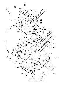
Fig. 1 is a perspective view of a vehicular side structure according to the
present invention;
Fig. 2 is an enlarged view of a region 2 of Fig. 1;
Fig. 3 is a perspective view of the vehicular side structure of Fig. 2 with a
roof panel disconnected therefrom
Fig. 4 is a perspective view of the vehicular side structure of Fig. 2 as the
structure is disassembled into a rail assembly and an arch assembly;
Fig. 5 is an exploded perspective view of the vehicular side structure of Fig.
2;
Fig. 6 is an exploded perspective view of the rail assembly shown in Fig. 4;
Fig. 7 is an exploded perspective view of the arch assembly shown in Fig. 4;
Fig. 8 is a view taken in a direction of an arrow 8 of Fig. 1;
Fig. 9 is an enlarged view of a region 9 of Fig. 2;
Fig. 10 is a cross-sectional view taken along line 10 -10 of Fig. 9;
Fig. 11 is a view showing steps of assembling the vehicular side structure
according to the present invention;
Fig. 12 is a cross-sectional view taken along line 12-12 of Fig. 9;
Fig. 13 is a cross-sectional view taken along line 13-13 of Fig. 9;
Fig. 14 is a cross-sectional view taken along line 14-14 of Fig. 9;
Fig. 15 is a cross-sectional view taken along line 15-15 of Fig. 9;
Fig. 16 is a cross-sectional view taken along line 16-16 of Fig. 9; and
Fig. 17 is a cross-sectional view taken along line 17-17 of Fig. 9.
DESCRIPTION OF EMBODIMENTS
CA 02819819 2013-06-03
- 11 -
A certain preferred embodiment of the present invention is described below
with reference to the accompanying drawings. Throughout the drawings,
arrows "Fr", "Rr", "L" and "R" denote a front direction, a rear direction, a
left
direction, and a right direction, respectively.
Embodiment
As shown in Fig. 1, a side structure 10 of a vehicle body includes a side sill
11 extending in a front-and-rear direction of the vehicle body and defining a
lower part of the side structure 10. The side structure 10 also includes a
front
pillar 12 extending upwardly from a front end of the side sill 11, and a
center
pillar 13 extending upwardly from a longitudinally intermediate portion of the
side sill 11. The side structure 10 further includes a rail assembly 15
supported by respective upper ends 12a, 13a of the front pillar 12 and the
center pillar 13 and defining an upper part of the side structure 10. The side
structure 10 further includes a side panel 16 covering outsides of the rail
assembly 15 and the center pillar 13. The side structure 10 further includes
an arch assembly 18 extending laterally of the vehicle body and having an end
located on the rail assembly 15. The side structure 10 further includes a roof
panel 20 supported by the arch assembly 18.
As shown in Fig. 2 and Fig. 3, the roof panel 20 includes a panel body 21
covering a top surface of the arch assembly 18, a front roof flange (roof
flange)
22 protruding forwardly of the vehicle body from a front end 21a of the panel
body 21, and a side roof flange 23 protruding laterally outwardly of the
vehicle
body from a side portion 21b of the panel body 21.
The front roof flange 22 is a projecting piece protruding forwardly of the
vehicle body from the front end 21a of the panel body 21. The front roof
flange
22 extends laterally of the vehicle body along the arch assembly 18. The front
roof flange 22 is joined to the arch assembly 18 by spot welding.
CA 02819819 2013-06-03
- 12 -
The front roof flange 22 has a vicinity 22a to the rail assembly 15 (more
specifically outer and inner portions 32, 36 of the rail assembly 15), and the
vicinity 22a has a roof recess 24 formed thereon. The roof recess 24 is a
recess
extending rearwardly of the vehicle body by a distance (depth) D1 from a front
edge 22b of the front roof flange 22. The roof recess 24 has its width W1. The
vicinity 22a is a portion corresponding to an outer projection 47, an upper
projection 65 and an inner projection 56 which are detailed later, and the
roof
recess 24 is contoured to avoid the outer projection 47, the upper projection
65
and the inner projection 56.
The side roof flange 23 is a projecting piece protruding laterally outwardly
of the vehicle body from the side portion 21b of the panel body 21. The side
roof flange 23 extends in the front-and-rear direction of the vehicle body
along
the rail assembly 15 and is coupled to the rail assembly 15 by spot welding.
As shown in Fig. 1, the rail assembly 15 is supported by the upper ends 12a
of the front pillar 12 and the upper end 13a of the center pillar 13 and
defines
the upper part of the side structure 10 of the vehicle body. As shown in Fig.
4,
the rail assembly 15 includes an outer member 31 extending in the front-and-
rear direction of the vehicle body and located laterally outwardly of the
vehicle
body. The rail assembly 15 also includes an inner member 35 disposed closer
to a lateral center of the vehicle body than the outer member 31. The rail
assembly 15 further includes a patch member 41 (Fig. 6) interposed between
the outer member 31 and the inner member 35.
As shown in Fig. 5 and Fig. 6, the outer member 31 includes an outer
portion 32 extending in the front-and-rear direction of the vehicle body and
located laterally outwardly of the vehicle body. The outer member 31 also
includes an outer extension portion 33 formed integrally with the outer
portion
32 and extends laterally of the vehicle body.
CA 02819819 2013-06-03
- 13 -
The outer extension portion 33 formed integrally with the outer portion 32
and extending laterally of the vehicle body has a lateral inner end 33a
overlapping a lateral outer end 62a of an upper member 62 of the arch assembly
18.
The outer extension portion 33 includes an extension body 45 extending
from the outer portion 32 toward the lateral center of the vehicle body. The
outer extension portion 33 also includes a front outer flange (outer flange)
46
protruding forwardly of the vehicle body from a front end 45a of the extension
body 45. The outer extension portion 33 further includes a rear outer flange
48
protruding rearwardly of the vehicle body from a rear end 45b of the extension
body 45.
The front outer flange 46 extends laterally of the vehicle body in
overlapping relationship to a front upper flange (upper flange) 64 of the
upper
member 62. The front outer flange 46 has a lateral inner end 46a including
the outer projection 47. The outer projection 47 protrudes a distance (height)
L1 such that the outer projection 47 underlies the upper projection 65 in
overlapping relationship thereto. The rear outer flange 48 has a lateral inner
end 48a defining an outer attachment hole 49.
The inner member 35 of the rail assembly 15 includes the inner portion 36
located closer to the lateral center of the vehicle body than the outer
portion 32
and extending in the front-and-rear direction of the vehicle body as does the
outer portion 32. The inner member 35 also includes an inner extension
portion 37 formed integrally with the inner portion 36 and extends towards the
lateral center of the vehicle body. The outer portion 32 and the inner portion
36 is substantially the same in length. The outer portion 32 cooperates with
the inner portion 36 to define a closed cross-sectional structure extending in
the
front-and-rear direction of the vehicle body.
CA 02819819 2013-06-03
- 14 -
The inner extension portion 37 formed integrally with the inner portion 36
and extending toward the lateral center of the vehicle body has a lateral
inner
end 37a overlapping a lateral outer end 72a of a lower member 72 of the arch
assembly 18.
The lateral inner end 37a of the inner extension portion 37 is located closer
to the lateral center of the vehicle body than the lateral inner end 33a of
the
outer extension portion 33. The outer extension portion 33 overlaps the inner
extension portion 37 such that the outer extension portion 33 cooperates with
the inner extension portion 37 to define a closed cross-sectional structure.
The inner extension portion 37 includes an extension body 54 extending
from the inner portion 36 toward the lateral center of the vehicle body. The
inner extension portion 37 also includes a front inner flange (inner flange)
55
protruding forwardly of the vehicle body from a front end 54a of the extension
body 54. The inner extension portion 37 further includes a rear inner flange
protruding rearwardly of the vehicle body from a rear end 54b of the extension
body 54.
The front inner flange 55 extends laterally of the vehicle body such that the
front inner flange 55 underlies a front lower flange (lower flange) 74 in
overlapping relationship to the front lower flange 74. The front inner flange
55
has a lateral inner end 55a located in a lower flange recess 75 (as will be
discussed later). The front inner flange 55 includes the inner projection 56
at a
lateral center 55b thereof. The inner projection 56 underlies the outer
projection 47 in overlapping relationship thereto. The inner projection 56
protrudes a height L1. The rear inner flange 57 has a first inner attachment
hole 58 formed through a lateral center 57a of the rear inner flange 57 and a
second inner attachment hole 59 formed through a lateral inner end 57b of the
rear inner flange 57.
=
CA 02819819 2013-06-03
- 15 -
The patch member 41 includes a reinforcing rail patch 42 disposed between
the outer portion 32 and the inner portion 36. The patch member 41 also
includes a patch extension portion 43 formed integrally with the reinforcing
rail
patch 42.
The reinforcing rail patch 42 extends in the front-and-rear direction of the
vehicle body within the closed cross-sectional structure defined by the outer
portion 32 and the inner portion 36. The reinforcing rail patch 42 has a
plurality of joined portions 42a coupled to an interior surface of the outer
portion 32 by spot welding. The coupling of the reinforcing rail patch 42 to
the
interior surface of the outer portion 32 by the spot welding reinforces the
outer
portion 32.
The patch extension portion 43 is formed integrally with the reinforcing rail
patch 42 and extends within the closed cross-sectional structure defined by
the
outer extension portion 33 and the inner extension portion 37. The patch
extension portion 43 has a plurality of joined portions 43a coupled to an
interior
surface of the outer extension portion 33 by spot welding. The coupling of the
patch extension portion 43 to the interior surface of the outer extension
portion
33 by the spot welding reinforces the outer extension portion 33.
By the rail patch 42 reinforcing the outer portion 32 and by the patch
extension portion 43 reinforcing the outer extension portion 33, rigidity of
the
rail assembly 15 can increase to thereby assure that the side structure of the
vehicle body is rigid.
As shown in Fig. 5 and Fig. 7, the arch assembly 18 includes the upper
member 62 adapted to be connected to the lateral inner end 33a of the outer
extension portion 33, and the lower member 72 adapted to be connected to the
lateral inner end 37a of the inner extension portion 37.
The upper member 62 of the arch assembly 18 is a beam member disposed
above the lower member 72 and having its lateral outer end 62a adapted to be
CA 02819819 2013-06-03
- 16 -
carried on a top surface of the outer extension portion 33. The upper member
62 includes an upper body 63 extending laterally of the vehicle body. The
upper member 62 also includes the front upper flange 64 protruding forwardly
of the vehicle body from a front end 63a of the upper body 63. The upper
member 62 further includes a rear upper flange 66 protruding rearwardly of the
vehicle body from a rear end 63b of the upper body 63.
The front upper flange 64 extends laterally of the vehicle body such that
the front upper flange 64 underlies the front roof flange 22 in overlapping
relationship to the front roof flange 22. The front upper flange 64 has a
lateral
outer end 64a including the upper projection 65 protruding forwardly of the
vehicle body.
The upper projection 65 protrudes forwardly of the vehicle body by a
distance (height) L1 from a front edge 64b of the front upper flange 64. The
upper projection 65 is in a location corresponding to the roof recess 24 such
that
the upper projection 65 protrudes forwardly of the vehicle body beyond a
bottom
24a of the roof recess 24.
The rear upper flange 66 has a first upper attachment hole 67 formed
through a lateral outer end 66a thereof and a second upper attachment hole 68
formed closer to the lateral center of the vehicle body than the first upper
attachment hole 67.
The lower member 72 of the arch assembly 18 is disposed below the upper
member 62 and has the lateral outer end 72a adapted to be carried on a top
surface of the lateral inner end 37a of the inner extension portion 37. The
upper member 62 and the lower member 72 overlap to thereby define a closed
cross-sectional structure extending laterally of the vehicle body.
The lower member 72 includes a lower body 73 extending laterally of the
vehicle body and the front lower flange 74 protruding forwardly of the vehicle
body from a front end 73a of the lower body 73. The lower member 72 also
CA 02819819 2013-06-03
- 17 -
includes a rear lower flange 76 protruding rearwardly of the vehicle body from
a
rear end 73b of the lower body 73.
The front lower flange 74 extends laterally of the vehicle body such that the
front lower flange 74 underlies the front upper flange 64 in overlapping
relationship to the front upper flange 64. The front lower flange 75 has the
lower flange recess 75 located closer to the lateral center of the vehicle
body
than a roof side spot welding region (discussed later) 92. The rear lower
flange
76 has a lower attachment hole 77 formed through a lateral outer end 76a
thereof.
As shown in Fig. 4 and Fig. 5, the upper member 62 is brought into
overlapping relationship to the lower member 72 with the outer extension
portion 33 overlapping the inner extension portion 37. In so doing, the
lateral
outer end 62a of the upper member 62 is brought to overlie the lateral inner
end
33a of the outer extension portion 33 in overlapping relationship to the
lateral
inner end 33a. Simultaneously, the lateral outer end 72a of the lower member
72 is brought to overlie the lateral inner end 37a of the inner extension
portion
37 in overlapping relationship to the lateral inner end 37a.
In this state, a bolt 81 is inserted through the first inner attachment hole
58 of the rear inner flange 57, the outer attachment hole 49 of the rear outer
flange 48 and the first upper attachment hole 67 of the rear upper flange 66,
after which a nut 82 threadedly engages a threaded shank 81a of the bolt 81
projecting out of the first upper attachment hole 67. The nut 82 is welded to
a
surface of the rear upper flange 66 in coaxial relationship to the first upper
attachment hole 67.
Then, a bolt 81 is inserted through the second inner attachment hole 59 of
the rear inner flange 57, the lower attachment hole 77 of the rear lower
flange
76 and the second upper attachment hole 68 of the rear upper flange 66, after
which a nut 82 threadedly engages a threaded shank 81a of the bolt 81
CA 02819819 2013-06-03
- 18 -
projecting out of the second upper attachment hole 68. The nut 82 is welded to
the surface of the rear upper flange 66 in coaxial relationship to the second
upper attachment hole 68.
As shown in Fig. 2 and Fig. 3, the front roof flange 22, the front upper
flange 64 and the front lower flange 74 are spot welded to one another. The
front outer flange 46 and the front inner flange 55 are coupled together by
spot
welding.
Spot welding the front roof flange 22, the front upper flange 64, the front
lower flange 74, the front outer flange 46 and the front inner flange 55 will
be
detailed with reference to Fig. 8 to Fig. 17.
As shown in Fig. 8 and Fig. 9, the side structure 10 of the vehicle body
provides a first spot welding region 91, the roof side spot welding region 92
located closer to the lateral center of the vehicle body than the first spot
welding
region 91, and a second spot welding region 93 located closer to the lateral
center of the vehicle body than the roof side spot welding region 92. The side
structure 10 of the vehicle body also provides a third spot welding region 94
located between the first spot welding region 91 and the roof side spot
welding
region 92. The side structure 10 of the vehicle body further provides a fourth
spot welding region 95 located laterally outwardly of the first spot welding
region 91, and a side spot welding region 96 located laterally outwardly of
the
fourth spot welding region 95.
As shown in Fig. 5 and Fig. 9, the front upper flange 64 includes the upper
projection 65 protruding forwardly of the vehicle body more than the front
roof
flange 22. The front outer flange 46 includes the outer projection 47
underlying the upper projection 65 in overlapping relationship to the upper
projection 65. The front inner flange 55 includes the inner projection 56
underlying the outer projection 47 in overlapping relationship to the outer
projection 47.
CA 02819819 2013-06-03
- 19 -
In other words, three projections, that is, the upper projection 65, the outer
projection 47 and the inner projection 56 protrude forwardly of the vehicle
body
more than the front roof flange 22. As shown in Fig. 10, these three
projections 65, 47, 56 are spot welded to one another in the first spot
welding
region 91.
In assembling the side structure 10 of the vehicle body, as shown in Fig. 11,
the roof panel 20 and the arch assembly 18 are assembled together into a roof
unit 102. Meanwhile, the rail assembly 15 and the side panel 16 are
assembled together into a rail unit 103. Thereafter, the roof unit 102 and the
rail unit 103 may be assembled together such that the three projections 65,
47,
56 protrude forwardly of the vehicle body more than the front roof flange 22
and
are spot welded together to define the first spot welding region 91 (Fig. 2
and
Fig. 9).
Typically, when a plurality of sheets is to be spot welded together, the
number of the sheets is preferably limited to three in order to ensure that
the
sheets are coupled together. With this in mind, as shown in Fig. 10, the
number of the projections spot welded together in the first spot welding
region
91 is three, that is, a strong coupling among the upper projection 65, the
outer
projection 47 and the inner projection 56 can be achieved by the spot welding.
The strong coupling of the upper member 62 (i.e., the arch assembly 18) to the
outer extension portion 33 and the inner extension 37 ensures sufficient
rigidity
of the side structure 10 of the vehicle body.
As shown in Fig. 9, the front roof flange 22 has the vicinity 22a to the rail
assembly 15, and the vicinity 22 corresponds to the outer projection 47, the
upper projection 65 and the inner projection 56 defines the roof recess 24.
The
roof recess 24 is contoured to avoid the outer projection 47, the upper
projection
65 and the inner projection 56, such that the outer projection 47, the upper
projection 65 and the inner projection 56 protrude a reduced distance
("height")
CA 02819819 2013-06-03
- 20 -
L1. By virtue of these projections 47, 65, 56, the side structure 10 of the
vehicle protrudes toward a windshield (not shown) by a reduced distance to
improve aesthetic design of the side structure 10.
Since the outer projection 47, the upper projection 65 and the inner
projection 56 protrude forwardly of the vehicle body more than the front roof
flange 22, the depth D1 of the roof recess 24 need not be so great as to allow
the
projections 47, 65, 56 to have a spot welding region. That is, the depth D1
can
be small because the projections 47, 65, 56 protrude by a distance sufficient
to
have a spot welding region.
Since the rood recess 24 has the small depth D1, it is possible to prevent
concentration of stress on the roof recess 24, i.e., to prevent deformation
beginning at the roof recess 24. Thus, sufficient rigidity of the side
structure
10 of the vehicle is ensured.
As shown in Fig. 3 and Fig. 9, the roof side spot welding region 92 is located
closer to the lateral center of the vehicle body than the first spot welding
region
91. In
the roof side spot welding region 92, three flanges, that is, the front roof
flange 22, the front upper flange 64 and the front lower flange 74 (a lateral
outer end 74a) are spot welded to one another. As the roof panel 20 and the
arch assembly 18 are assembled together into the roof unit 102, the three
flanges 22, 64, 74 are spot welded to one another to define the roof side spot
welding region 92.
Since the three flanges 22, 64, 74 are spot welded together, the flanges 22,
64, 74 can be firmly coupled to one another to thereby sufficient coupling
strength of the roof unit 102.
The front inner flange 55 has a downwardly projecting portion 55c at a
location corresponding to the front lower flange 74 (the lateral outer end
74a).
The downwardly projecting portion 55c avoids interfering the roof side spot
welding region 92.
CA 02819819 2013-06-03
- 21 -
As shown in Fig. 3 and Fig. 9, the front lower flange 74 has the lower flange
recess 75. The lower flange recess 75 is located closer to the lateral center
of
the vehicle body than the rood side spot welding region 92. The lateral inner
end 55a of the front inner flange 55 terminates in the lower flange recess 75.
As shown in Fig. 13, the front roof flange 22, the front upper flange 64 and
the front inner flange 55 are spot welded to one another in the second spot
welding region 93 located near the roof side spot welding region 92 and in the
lower flange recess 75. Since these three flanges 22, 64, 55 are spot welded
together, the flanges 22, 64, 55 can be firmly coupled together.
In the roof side spot welding region 92, the front upper flange 64 and the
front lower flange 74 (the lateral outer end 74a) are spot welded to each
other.
In the second spot welding region 93, the front upper flange 64 and the front
inner flange 55 are spot welded to each other. Since the second spot welding
region 93 is located near the roof side spot welding region 92, the front
inner
flange 55 (the inner extension portion 37) is kept horizontally continuous
relative to the front lower flange 74 (the lower member 72), thereby providing
a
connection 19 between the rail assembly 15 and the arch assembly 18 with a
closed cross-section. By virtue of the closed cross-section of the connection
19,
sufficient rigidity of the connection 19 is ensured.
To assemble the side structure 10 of the vehicle body, the arch assembly 18
and the roof panel 20 are assembled together into the roof unit 102, and the
rail
assembly 15 and the side panel 16 are assembled together into the rail unit
103.
Thereafter, the roof unit 102 and the rail unit 103 are assembled together.
The assemblage of the roof unit 102 and the rail unit 103 requires carrying
the lateral outer end 62a of the upper member 62 onto the lateral inner end
33a
of the outer extension portion 33 such that the lateral outer end 62a overlies
the
lateral inner end 33a while carrying the lateral outer end 72a of the lower
member 72 onto the lateral inner end 37a of the inner extension portion 37
such
CA 02819819 2013-06-03
- 22 -
that the lateral outer end 72a overlies the lateral inner end 37a. Thus, the
roof
unit 102 and the rail unit 103 can be assembled together easily after the roof
unit 102 is assembled and the rail unit 103.
As shown in Fig. 5 and Fig. 9, the third spot welding region 94 is located
laterally outwardly of the lower member 72 and closer to the lateral center of
the vehicle than the outer extension portion 33. The third spot welding region
94 is a region where the three flanges, that is, the front roof flange 22, the
front
upper flange 64 and the front inner flange 55 are spot welded to one another,
as
shown in Fig. 15. Since these three flanges 22, 64, 55 are spot welded
together, the flanges 22, 64, 55 can be firmly coupled together. The third
spot
welding region 94 is located closer to the lateral center of the vehicle body
than
the first spot welding region 91.
The fourth spot welding region 95 is located laterally outwardly of the
upper member 62. The fourth spot welding region 95 is a region where the
three flanges, that is, the front roof flange 22, the front outer flange 46
and the
front inner flange 55 are spot welded to one another, as shown in Fig. 16.
Since these three flanges 22, 46, 55 are spot welded together, the flanges 22,
46,
55 can be firmly coupled together.
The fourth spot welding region 95 is located laterally outwardly of the first
spot welding region 91, as shown in Fig. 9. The first spot welding region 91
is
located between the third spot welding region 94 and the fourth spot welding
region 95. No portion of the front roof flange 22 is spot welded in the first
spot
welding region 91. Since the third and fourth spot welding regions 94, 95 are
located on both sides of the first spot welding region 91, the front roof
flange 22
is fixed on the both sides of the first spot welding region 91 to thereby
provide
sufficient coupling strength of the front roof flange 22.
The roof side spot welding region 92 is located between the second spot
welding region 93 and the third spot welding region 94. The three flanges,
CA 02819819 2013-06-03
- 23 -
that is, the front roof flange 22, the front upper flange 64 and the front
lower
flange 74 are spot welded to one another in the roof side spot welding region
92.
In the second and third spot welding regions 93, 94, the three flanges, that
is, the front roof flange 22, the front upper flange 64 and the front inner
flange
55 are spot welded to one another. Thus, in a region from the second spot
welding region 93 through the roof side spot welding region 92 to the third
spot
welding region 94, the front lower flange 74 can be firmly coupled to the
front
inner flange 55 via the front roof flange 22 and the front upper flange 64.
Since the front lower flange 74 is firmly coupled to the front inner flange
55, the
lower member 72 is firmly coupled to the inner extension portion 37.
In the first spot welding region 91, the upper projection 65 and the outer
projection 47 are spot welded to each other, and hence the front upper flange
64
can be firmly coupled to the front outer flange 46. Since the front upper
flange
64 is firmly coupled to the front outer flange 46, the upper member 62 is
firmly
coupled to the outer extension portion 33.
Since the lower member 72 is firmly coupled to the inner extension portion
37 while the upper member 62 is firmly coupled to the outer extension portion
33, the arch assembly 18 is coupled to the rail assembly 15 in a preferred
manner.
The roof side spot welding region 92 and the second and third spot welding
regions 93, 94 are located at given intervals and closer to the lateral center
of
the vehicle body than the first spot welding region 91. Since the spot welding
regions 92, 93, 94 are located away from the first spot welding region 91
toward
the lateral center of the vehicle body, a stress applied to the connection 19
between the rail assembly 15 and the arch assembly 19 can be dispersed to the
spot welding regions 92, 93, 94 or the first spot welding region 91 in a
preferred
manner. Thus, sufficient rigidity of the connection 19 between the rail
assembly 15 and the arch assembly 18 is ensured.
CA 02819819 2013-06-03
- 24 -
That is, as shown in Fig. 3 and Fig. 9, the upper member 62 and the outer
extension portion 33 are coupled together via the coupling of the upper
projection 65 to the outer projection 47 in the first spot welding region 91.
The
lower member 72 and the inner extension portion 37 are coupled together via
the coupling of the front lower flange 74 (the lateral outer end 74a) to the
front
inner flange 55 (the lateral inner end 55a) in the region from the spot
welding
regions 93 through the spot welding region 92 to the spot welding region 94.
That is, the first spot welding region 91 in which the upper member 62 and
the outer extension portion 33 are coupled together is located away from the
spot welding regions 92, 93, 94 in which the lower member 72 is coupled to the
inner extension portion 37 through the front upper flange 64. As a result, a
stress applied to the connection 19 between the rail assembly 15 and the arch
assembly 18 can be dispersed to the spot welding regions 92, 93, 94 or the
first
spot welding region 91 in a preferred manner. Thus, sufficient rigidity of the
connection 19 between the rail assembly 15 and the arch assembly 18 is
ensured.
As shown in Fig. 9, the side spot welding region 96 is located laterally
outwardly of the fourth spot welding region 95 and closer to the lateral
center of
the vehicle body than the inner portion 36 (Fig. 6). As shown in Fig. 17, the
side spot welding region 96 is a region where three elements, that is, the
front
roof flange 22, a side flange 16a of the side panel 16, and a joined portion
55d of
the front inner flange 55 are spot welded to one another. Since these three
elements 22, 16a, 55d are spot welded together, the three elements 22, 16a,
55d
can be firmly coupled together. The side flange 16a of the side panel 16 is
coupled to a joined portion 36a of the inner portion 36.
As discussed above, the outer extension portion 33 is formed integrally with
the outer portion 32, the inner extension portion 37 is formed integrally with
the inner portion 36, and the outer extension portion 33 cooperates with the
CA 02819819 2013-06-03
- 25 -
inner extension portion 37 to define the closed cross-sectional structure, as
shown in Fig. 3. The arch assembly 18 has the closed cross-sectional structure
defined by the upper member 62 and the lower member 72, as shown in Fig. 7.
As shown in Fig. 4, the upper member 62 is adapted to be carried on the top
surface of the outer extension portion 33, and the lower member 72 is adapted
to be carried on a top surface of the inner extension portion 37.
This means that the arch assembly 18 having the closed cross-sectional
structure is adapted to be provided to the outer and inner extension portions
33,
37 having the closed cross-sectional structure, thereby rigidifying the side
structure 10 of the vehicle body.
The rail assembly 15 and the arch assembly 18 are arranged substantially
perpendicularly to each other. If the rail assembly 15 and the arch assembly
18 were connected to each other at a junction 26 (Fig. 4), a stress would be
concentrated on the junction 26 in which case it would be difficult to keep
the
junction 26 rigid.
In this regard, the outer extension portion 33 is formed integrally with the
outer portion 32, and the inner extension portion 37 is formed integrally with
the inner portion 36. The upper member 62 is provided on the outer extension
portion 33, and the lower member 72 is provided on the inner extension portion
37. This means that the rail assembly 15 is connected to the arch assembly 18
at the connection 19 located away from the junction 26. As a result, the
junction 26 can be kept rigid. Thus, a load F (Fig. 4) from a front direction
of
the vehicle body can be transmitted through the rail assembly 15 and the
junction 26 to the arch assembly 18 in a preferred manner.
As shown in Fig. 2, the roof panel 20 is disposed above the arch assembly
18 to cover the arch assembly 18. In placing the roof panel 20 onto the arch
assembly 18, the side roof flange 23 of the roof panel 20 and an end 22c of
the
CA 02819819 2013-06-03
- 26 -
front roof flange 22 are welded to the outer portion 32 of the rail assembly
15
and the side panel 16 (the side flange 16a).
As shown in Fig. 4, the outer extension portion 33 is formed integrally with
the outer portion 32, thereby reducing a fabrication tolerance of the outer
portion 32. To the outer portion 32 of the reduced fabrication tolerance, the
side roof flange 23 of the roof panel 20 and the end 22c of the front roof
flange
22 are welded, as shown in Fig. 2. More specifically, the side roof flange 23
and the end 22c of the front roof flange 22 can be accurately welded to
desired
locations of the outer portion 32 to thereby accurately position the roof
panel 20
in place.
As shown in Fig. 3, additionally, the outer portion 32 extends along the
inner portion 36 by substantially the same distance as the inner portion 36
such
that the outer portion 32 extends along the entire length of a flange of the
roof
panel, that is, alongside the side roof flange 23 and the end 22c of the front
roof
flange 22.
Since the outer portion 32 extends alongside the side roof flange 23 and the
end 22c of the front roof flange 22, the side roof flange 23 and the end 22c
of the
front roof flange 22 can be disposed on the outer portion 32 without spanning
a
boundary between the outer portion 32 and the inner portion 36. Thus, the
side roof flange 23 and the end 22c of the front roof flange 22 (that is, the
roof
panel 20) can be accurately welded to desired locations of the outer portion
32.
As a result, the roof panel 20 can be accurately positioned in place.
It will be appreciated that the vehicle body side structure according to the
present invention is not limited to that in the embodiment discussed above but
may be modified or improved. For example, the front roof flange 22 of the roof
panel 20 need not have the roof recess 24 to allow for the first spot welding
region 91. That is, without the roof recess 24 being formed on the front roof
flange 22, the upper projection 65, the outer projection 47 and the inner
CA 02819819 2013-06-03
- 27 -
projection 56 may protrude a distance adjusted to allow for the first spot
welding region 91. In this case, stress concentration can be prevented more
effectively than if the roof recess 24 is formed on the front roof flange 22.
It is noted that elements of the side structure 10 in the embodiment such as
the rail assembly 15, the side panel 16, the arch assembly 18, the roof panel
20,
the panel body 21, the front roof flange 22, the roof recess 24, the outer
portion
32, the outer extension portion 33, the inner portion 36, the inner extension
portion 37, the patch member 41, the reinforcing rail patch 42, the patch
extension portion 43, the extension body 45 of the outer extension portion,
the
front outer flange 46, the outer projection 47, the extension body 54 of the
inner
extension portion, the front inner flange 55, the inner projection 56, the
upper
member 62, the upper body 63, the front upper flange 64, the upper projection
65, the lower member 72, the lower body 73, the front lower flange 74 and the
lower flange recess 75 may have shapes or constructions not limited to those
discussed in the embodiment but modified appropriately.
INDUSTRIAL APPLICABILITY
The present invention is preferably applicable to an automobile having a
vehicle body whose side structure including a rail assembly located laterally
outwardly thereof, an arch assembly disposed on the rail assembly, and a roof
panel supported by the arch assembly.
Reference Signs List:
10...a side structure of a vehicle body, 15...a rail assembly, 16...a side
panel,
18...an arch assembly, 20...a roof panel, 21...a panel body, 22...a front roof
flange (roof flange), 24...a roof recess, 32...an outer portion, 33...an outer
extension portion, 33a...a lateral inner end of the outer extension portion,
36...an inner portion, 37...an inner extension portion, 37a...a lateral inner
end
of the inner extension portion, 41...a patch member, 42...a reinforcing rail
patch, 43...a patch extension portion, 45...an extension body of the outer
CA 02819819 2013-06-03
- 28 -
extension portion, 46...a front outer flange (outer flange), 46a...a lateral
inner
end of the front outer flange, 47...an outer projection, 54...an extension
body of
the inner extension portion, 55...a front inner flange (inner flange), 56...an
inner projection, 62...an upper member, 62a...a lateral outer end of the upper
member (end of the arch assembly), 63...an upper body, 64...a front upper
flange (upper flange), 65...an upper projection, 72...a lower member, 72a...a
lateral outer end of the lower member (end of the arch assembly), 73...a lower
body, 74...a front lower flange (lower flange), 75...a lower flange recess,
91...a
first spot welding region, 92...a roof side spot welding region, 93...a second
spot
welding region, 94...a third spot welding region, 95...a fourth spot welding
region