Note: Descriptions are shown in the official language in which they were submitted.
CA 02820009 2013-07-04
-1-
APPARATUS FOR SEPARATING INDIVIDUAL FLAT, BENDABLE
OBJECTS FROM THE UNDERSIDE OF A STACK OF SUCH OBJECTS
FIELD OF THE INVENTION
The invention is in the area of the conveying of flat,
bendable objects, in particular printed products. The
apparatus serves for separating individual flat, bendable
objects from the underside of a stack of such objects and
for the onward conveying of the objects. The apparatus
serves, in particular, for separating individual printed
products from the underside of a stack of printed
products and for the onward conveying of the printed
products.
BACKGROUND OF THE INVENTION
WO 2008/000099 describes an apparatus for separating
individual flat, bendable printed products from the
underside of a stack of printed products and for the
onward conveying of the printed products. The apparatus
includes a stacking area having a support region in which
the stack is supported toward the bottom. The apparatus
further includes a roller carpet having a plurality of
rollers which are freely rotatable about their
longitudinal axis, are moved past under the support
region along a circular path and at the same time support
the printed product stack toward the bottom. The rollers
are fastened on a rotatable roller wheel or are coupled
to the same for this purpose. In addition, the apparatus
includes circulating separating and holding means in the
form of suction elements and grippers which cooperate in
pairs for separating the objects from the underside of
the stack. The rollers are moved past under the stack in
the support region in the same direction as the
separating and holding means.
CA 02820009 2013-07-04
-2-
The apparatus also includes an onward conveying device
for the onward conveying of the separated objects.
The removal of individual printed products occurs by a
suction element, which is circulating in the support
region, firmly attaching itself from below to the bottom-
most printed product and removing the same downward by
means of its circular movement. When the printed product
is being removed, it is inserted by way of the leading
edge into the gripper mouth of a gripper which is
circulating in a synchronized cycle in the support
region. The gripper grasps the printed product with a
closing movement. In the same process step, a following
support roller is moved between the underside of the
stack and the removed printed product and peels said
printed product from the stack during its movement
through the support region.
Whilst the suction element is then released from the
printed product and is moved away from the same, the
circulating, closed gripper conveys the peeled-off
printed product further downward toward an onward
conveying device and transfers it to the onward conveying
device. During this operation, the removed printed
product is entrained in part into the inner region of the
roller carpet and in this position is entrained a little
bit further synchronously with the roller carpet before
it is deposited onto the conveyor belt of the onward
conveying device.
EP 2 128 055 A2 also describes an apparatus for
separating printed products from the underside of a stack
of printed products and for the onward conveying of the
separated printed products. The apparatus includes a
stacking area having a support region in which the stack
is supported downward. In addition, the apparatus
CA 02820009 2013-07-04
-3-
includes a circulating roller carpet having a plurality
of rollers which are freely rotatable about their
longitudinal axis, are moved through the support region
and, at the same time, support the stack toward the
bottom. In addition, the apparatus includes circulating
separating and holding means in the form of suction means
and grippers for separating the objects from the
underside of the stack. The rollers are moved past under
the stack in the support region in the same direction as
the separating and holding means.
The apparatus also includes an onward conveying device
for the onward conveying of the separated objects.
The rollers of the roller carpet are coupled to at least
one roller wheel. The coupling is designed according to
said embodiment in such a manner that the rollers are
pivotable in relation to the roller wheel with their
longitudinal axis.
The removal of individual printed products occurs by a
suction element, which is circulating in the support
region, firmly attaching itself from below to the bottom-
most printed product and removing the same downward by
means of its circular movement. When the printed product
is being removed, it is inserted by way of the leading
edge into the gripper mouth of a gripper which is
circulating in a synchronized cycle in the support
region. The gripper grasps the printed product with a
closing movement.
Whilst the suction element is then released from the
printed product and is moved away from the same, a
following support roller is moved between the underside
of the stack and the released printed product and peels
the same from the stack during its movement through the
CA 02820009 2013-07-04
-4-
support region. The circulating, closed gripper conveys
the printed product further downward to an onward
conveying device and transfers it to the onward conveying
device. Said method steps correspond to the method
described in WO 2008/000099. In the case of said
operation according to the present embodiment, however,
the removed printed product is guided completely into the
inner region of the roller carpet.
The rollers, in turn, are pivoted by a control element in
a release region of the circular path. This means that an
opening, through which the onward conveying device is
guided, is created in the roller carpet in the release
region.
The printed product, which is conveyed completely into
the inner region of the roller carpet by the gripper, is
then guided out of the inner region through the opening
in the roller carpet outside the region of influence of
the rollers and transferred to the onward conveyor belt
of the onward conveying device.
The disadvantage of the described apparatuses, however,
is that the rollers support the stack of printed products
during their movement through the support region only in
a local manner, i.e. from point to point, and the linear
support region is entrained correspondingly with the
rollers through the support region.
If then, for certain reasons no printed products are
removed over one or several cycles, i.e. so-called empty
cycles are generated with non-occupied grippers, the
stack underside can become increasingly curved due to the
flexing of the support rollers which roll under the
stack. An empty cycle is therefore characterized in that
CA 02820009 2013-07-04
-5-
no product is sucked up and the corresponding gripper
remains empty.
In the case of empty cycles, it is true that no object is
removed from the stack by the suction element and the
gripper, but the roller carpet continues to run past
under the stack in the circulating direction. As a result
of the rollers moving through the support region, the
printed products bulge in a downwardly directed bag-like
manner between in each case two rollers, which, when
viewed over the support region, produces wave-like
deformation of the underside of the stack. Said bulges
are moved in each case together with the rollers in a
wave-like manner through the support region in the
circulating direction of the rollers. The operation
connected thereto is called flexing.
Said unwanted effect occurs in particular with thin, not
very rigid printed products and leads to mutual
displacements of the printed products inside the stack.
As a result faults can occur when separating the printed
products by, for example, instead of individual printed
products being separated off, several printed products
are removed at the same time or by products being
randomly, i.e. out of cycle, removed from the stack.
The bag-like bulging of the stack of printed products
down through between the rollers also occurs on account
of gravity when the apparatus is not moving, when the
rollers are stationary in the support region. When the
operation is resumed, the bulges are moved together with
the rollers in a wave-like manner through the support
region, which leads to the above-mentioned effect.
CA 02820009 2013-07-04
-6-
SUMMARY OF EMBODIMENTS OF THE INVENTION
Consequently, it is the object of the invention to create
an apparatus which serves the same purposes as the
apparatuses described in the introduction where, however,
no flexing occurs even in the case of very thin printed
products, and which consequently allows for as perfect a
removal as possible from the stack even in the case of
comparatively thin printed products.
An apparatus according to an aspect of the invention
corresponds in particular to a further development of the
apparatus disclosed in WO 2008/000099 and EP 2 128 055
A2. In a corresponding manner, the apparatus features
described in conjunction with said two disclosure
documents are also applicable to the present invention.
An apparatus according to an aspect of the invention for
separating individual flat, bendable objects from the
underside of a stack of such objects and for the onward
conveying of the separated objects includes:
- a stacking area having a support region;
- a roller arrangement produced from a plurality of
rollers, said roller arrangement supporting the stack
from below in the support region;
- separating and holding means for separating the
objects from the underside of the stack in the support
region; and
an onward conveying device for the onward conveying
of the separated objects.
According to an aspect, the separating and holding means
are arranged so as to circulate along a circular path. In
a preferred manner, the rollers of the roller arrangement
are movable past under the stack in the support region.
The rollers are preferably moved past under the stack in
CA 02820009 2013-07-04
-7-
the same direction as the separating and holding means
which circulate below the support region.
According to an aspect, the rollers extend over a support
face in the support region. The support face can be
realized as a plane or curved face.
The roller arrangement can be designed for a translatory
movement of the rollers in the support region. The
translatory movement can be, for example, a movement back
and forth.
According to an aspect of the invention, the rollers are
moved along a circular path which leads past the support
region. Thus, a plurality of rollers which are spaced
apart from one another can be arranged, for example,
along the circular path, which rollers form a so-called
circulating roller carpet which is moved past under the
stack in the support region and supports said stack
downward.
The rollers are preferably moved spaced apart from one
another at least in the support region.
According to a further aspect of the invention, it is
also possible to provide two roller arrangements which
are arranged opposite one another and together form the
support plane in the support region. In a preferred
manner, the two roller arrangements are moved in each
case along a circular path. In a preferred manner, the
two roller arrangements are realized in a mirror
symmetrical manner with respect to one another. It is
possible to provide a gap, which is arranged in
particular in the centre in the support region between
the rollers which are located opposite one another,
through which gap, for example, the circulating
CA 02820009 2013-07-04
-8-
separating and holding means can be moved. The roller
arrangements can be mounted, for example, in each case on
a circulating roller wheel.
According to an aspect, the rollers of the roller
arrangement are mounted at least in the support region in
each case so as to be freely rotatable about their
longitudinal axis. The direction of movement of the
rollers through the support region extends transversely
with respect to the longitudinal axis of the rollers.
According to an aspect of the invention, the apparatus
includes a supporting and stopping device for positioning
a supporting and stopping means into a holding position
between the stack and the rollers of the roller
arrangement. I.e. in the holding position the supporting
and stopping element lies below the stack. It is
preferably in direct contact with the bottom-most object
of the stack. The supporting and stopping means which is
located in the holding position and the rollers of the
roller arrangement lie additionally in the support region
in a preferred manner in planes which extend parallel to
one another.
According to an aspect, the supporting and stopping
device is arranged laterally of the support region. In a
preferred manner, the supporting and stopping device is
designed and arranged such that the supporting and
stopping means is extended toward the support region
substantially in the same direction as the direction of
movement of the rollers in the direction of the support
region and can be correspondingly retracted out of the
support region in the opposite direction to said
direction of movement.
CA 02820009 2013-07-04
-9-
According to an aspect, the supporting and stopping means
is a planiform supporting and stopping element. In the
holding position, the supporting and stopping means can
extend partially or completely over the support region.
The support region is defined in an expedient manner by
the contact face of the objects. The supporting and
stopping means exerts an additional supporting function
on the stack along with the rollers. Consequently, it can
be viewed as a further support means.
In the holding position, the supporting and stopping
means extends along the direction of movement, in
particular, when viewed in the circumferential direction
of the rollers, in a preferred manner over at least two
rollers. I.e. the supporting and stopping means forms a
support face over at least one free gap which lies
between two rollers. Said support face prevents the
objects of the stack sagging between the two rollers. In
a preferred manner, the supporting and stopping means
extends over several rollers and spans several spaces
which are realized by the rollers.
According to an aspect, the supporting and stopping means
is flexible. In particular, the supporting and stopping
means can also be resilient.
In addition, the supporting and stopping means can also
include an articulated joint which bestows the
corresponding flexibility on said supporting and stopping
means.
The supporting and stopping means can be realized in one
part or in multiple parts, in particular it can have one
member or multiple members. In addition, the supporting
and stopping means can be constructed with one layer or
CA 02820009 2013-07-04
-10-
multiple layers and can include, for example, two, three,
four, five or more layers.
The supporting and stopping means can be present in the
form of a chain, a belt, a bundle of ties or a strip.
According to an aspect, the supporting and stopping means
is self-supporting. I.e the supporting and stopping means
is not deformed or is only deformed insignificantly as a
result of gravity.
The supporting and stopping element can be, for example,
of metal, such a spring steel, of plastics material,
leather or of a composite substance with several
materials. The supporting and stopping means can be, in
particular, a metal sheet. In addition, the supporting
and stopping element can also be plate-shaped.
According to an aspect, the supporting and stopping
element is constructed in such a manner that said
supporting and stopping element comprises a slight amount
of static friction toward the stack such that pulling the
supporting and stopping element back out of the support
region does not result in displacing the objects or in
damage to the same.
A multiple-layered supporting and stopping element can
additionally comprise a damping layer to reduce the
noise. The damping layer can be, for example, of plastics
material. The damping layer can be, for example, an
outside or inside layer.
According to a further aspect of the invention, the
supporting and stopping element can be strip-shaped. In
the holding position, the strip-shaped supporting and
CA 02820009 2013-07-04
-11-
stopping element lies at an angle to the longitudinal
axis of the rollers, in particular at right angles.
The supporting and stopping device can also include, when
viewed in the direction of insertion or transversely with
respect to the longitudinal axis, several supporting and
stopping elements arranged side by side, in particular
parallel side by side. According to said design variant,
in a preferred manner the supporting and stopping
elements are strip-shaped.
It is also possible to provide several, in particular
strip-shaped, supporting and stopping elements which are
moved into the support region. They can lie parallel to
one another.
The supporting and stopping device also includes an
actuating means, in particular pneumatic means, for
extending the supporting and stopping means in the
direction of the support region. The term "extending"
refers to the guiding of the supporting and stopping
means into the support region. The actuating means is
preferably to be designed also for retracting the
supporting and stopping means out of the support region.
The term "retracting" refers to the guiding of the
supporting and stopping means out of the support region.
For example, the retracting can be a withdrawing. In
place of pneumatic means, the actuating means can also
include hydraulic or electric means for extending and
retracting.
As the apparatus according to an aspect of the invention
runs at a comparatively high operating speed, the
extending and the retracting of the supporting and
stopping element is also effected at a comparatively high
speed. Thus, for example, up to 15 objects can be removed
CA 02820009 2013-07-04
-12-
from the stack per second. At said speeds, the extending
of the supporting and stopping element in the direction
of the support region is similar rather to an injection
in the direction of the support region. The synchronized
cycle movement of the supporting and stopping element is
all the more important here for the operation to separate
the objects.
In an expedient manner, the actuating means is actuated
by means of a control device. The control device can be a
central control device which also controls the operation
of the apparatus.
According to an aspect, as already mentioned, the
actuating means is actuated in a synchronized cycle with
the operation of the apparatus. In this way, the
extending of the supporting and stopping means in the
direction of the support region can be synchronized with
an approaching empty cycle in which no object is removed,
or with a shut-down of the apparatus. In addition, in
this way the withdrawing of the supporting and stopping
means out of the support region can also be coordinated
with the first cycle by way of which an object is removed
from the stack.
The longitudinal axes of the rollers extend in the
support region, i.e. in the region of the stack where
they support the stack toward the bottom, preferably
parallel to the underside of the stack. As a rule, the
longitudinal axes of the rollers extend horizontally or
slightly inclined in the support region.
According to an aspect, the rollers of the roller
arrangement are coupled to at least one circulating
roller wheel. The coupling of the rollers to a
circulating roller wheel allows for simple construction
CA 02820009 2013-07-04
-13-
of the apparatus and reliable guiding of the roller
arrangement along its circular path.
According to an aspect, the separating and holding means
are arranged on a circulating carrier wheel.
According to an aspect, the carrier wheel and the roller
wheel have the same circular direction.
According to an aspect, the roller wheel and the carrier
wheel comprise parallel axes of rotation.
According to an aspect, the releasing and holding means
include at least one suction element and at least one
gripper. The suction element and the gripper cooperate in
each case in pairs.
The removing or separating of individual objects, in
particular printed products, occurs by the suction
element, which circulates in the support region,
firmly
attaching itself from below to the bottom-most object and
removing the same downward by means of its circular
movement. When the object is being removed, it is
inserted by way of the leading edge into the gripper
mouth of a gripper which is circulating in a synchronized
cycle in the support region. The gripper grasps the
object with a closing movement. In the same process step,
a following support roller is moved between the underside
of the stack and the separated object and peels the same
off the stack during its movement through the support
region.
Whilst the suction element is then released from the
object and is moved away from the same, the circulating,
closed gripper conveys the peeled-off object further
downward toward an onward conveying device and transfers
it to the onward conveying device. During this operation,
the removed object is entrained in part or completely
CA 02820009 2013-07-04
-14-
into the inner region of the roller arrangement and in
this position is entrained a little bit further in a
synchronous manner with the roller carpet before then
being transferred to an onward conveying device.
According to an aspect of the invention, the rollers are
coupled to the roller wheel in such a manner that they
are pivotable with their longitudinal axes in each case
with reference to the roller wheel. The rollers, in this
connection, are pivotable in a release region along the
circular path by means of a control element. I.e. the
roller arrangement is pivoted up in the release region.
In this case, the onward conveying device is guided by
the pivoted-up roller arrangement.
According to said aspect, the releasing and holding means
move the objects in the support region into an inner
region of the roller arrangement completely by means of
the moving roller arrangement. The roller arrangement is
pivoted up in a release region, which is arranged in the
direction of circulation of the rollers and in which the
objects leave the inner region again, for the onward
conveying of the objects.
The pivoting of the roller in the release region occurs
preferably by means of a fixed link guiding means, e.g.
in the form of a control runner. The rollers roll, for
example, off the control runner. In this case, use is
made of the fact that the rollers are mounted so as to be
freely rotatable about their longitudinal axes in a
roller carrier. Thus, it is possible to use a rigid link
guiding means without any further movable control
elements. The link guiding means is preferably arranged
in the interior of the circular path and presses on the
rollers or rather the roller arrangement from the inside.
As an alternative to this, however, the rollers can also
CA 02820009 2013-07-04
-15-
be lengthened toward the back beyond the roller carrier
such that the rear ends of the rollers are pressed toward
one another by a link guide means, which is arranged
outside the roller arrangement, and thus their front ends
are moved apart. Other mechanical, pneumatic, hydraulic
or electric actuating means can also be used for pivoting
the rollers. The roller carriers are preferably mounted
on the roller wheel so as to be pivotable about a pivot
axis.
According to a further development of the apparatus
according to an aspect of the invention, said apparatus
comprises two roller wheels located opposite one another
with roller sets which face one another and are
preferably symmetrical with respect to one another. The
axes of the two roller wheels are preferably coaxial, but
can also be inclined, for example, toward the interior of
the apparatus. In certain applications, however, it can
also be expedient to have only one single roller wheel.
According to an aspect of the invention, the at least one
roller wheel and the carrier wheel of the suction means
and the gripper comprise parallel axes of rotation, as a
result of which simple design is possible. In addition,
the carrier wheel and the at least one roller wheel are
preferably driven in a rotating manner at the same
angular speeds, preferably by the same driving means and
coupled together by a gearing unit.
The apparatus according to the invention can be developed
as a feeder unit which is, for example, movable. Such a
feeder unit is designed, for example, to be refilled with
objects manually by personnel.
However, the apparatus according to the invention can
also be incorporated in a conveying or processing system,
CA 02820009 2013-07-04
-16-
the objects being supplied to the stack individually or
in groups by means of device parts connected upstream and
the stack serving, for example, as a buffer.
During the operation of the apparatus, objects are
removed from the stack in a predetermined cycle.
The removed objects can be deposited and conveyed onward
on the conveyor belt of an onward conveying device
individually or as a stream.
Where at least one empty cycle occurs or where the
apparatus is taken out of operation, a supporting and
stopping means is then positioned (beforehand) in the
support region between the stack and the roller
arrangement.
This occurs for instance by the supporting and stopping
means being inserted between two rollers in the direction
of the support region below the support region. The
supporting and stopping means inserted between the
rollers is moved by the rollers in the circulating
direction of the rollers toward the support region and is
positioned in the support region between the stack and
the roller arrangement.
The solution according to the invention allows the
problems of flexing on the underside of the stack to be
eliminated with little expenditure and little technical
means. The supporting and stopping element inserted into
the support region prevents the objects from bulging
through between the rollers of the roller arrangement and
consequently a flexing inside the stack.
The solution according to the invention also protects the
objects to be processed. This is achieved by the
CA 02820009 2013-07-04
-17-
supporting and stopping means not being extended directly
between the rollers and the stack by the actuating means.
Rather, the supporting and stopping means is extended
between the rollers below the support region and outside
the contact region with the stack and is entrained by the
rollers following from below in the direction of the
support region and is positioned below the stack.
The solution according to the invention also comprises
the advantage that existing apparatuses, such as those
disclosed in WO 2008/000099 Al and EP 2 128 055 A2, are
able to be fitted in retro with the supporting and
stopping device according to the invention.
The object of the invention is explained below in detail
by way of preferred exemplary embodiments which are shown
in the accompanying drawings, in which, in each case in a
schematic representation:
BRIEF DESCRIPTION OF THE DRAWINGS
Figure 1 shows a side view of a first embodiment of
the apparatus according to the invention;
Figures 2a,2b show an abstracted side view of the first
embodiment;
Figure 3 shows a side view of a second embodiment
of the apparatus according to the
invention.
In principle, identical parts in the Figures are provided
with identical references.
CA 02820009 2013-07-04
-18-
DETAILED DESCRIPTION OF THE DRAWINGS
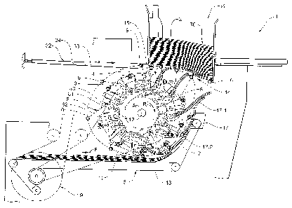
Figure 1 shows a first embodiment of the apparatus 1
according to the invention for separating individual
flat, bendable objects 2 from a stack 30 of said objects
2 and for the onward conveying of the separated objects
2. Figure 1 corresponds to a side view with an angle of
view parallel to the axis of rotation A of a carrier
wheel 3 and roller wheel 7.
The apparatus 1 comprises a stacking area 31 in which
flat objects 2 which are bendable at least parallel to
the axis of rotation A, in particular printed products,
are stacked lying on a roller arrangement in the form of
a roller carpet which is yet to be described. A support
region 14 is realized in a corresponding manner in the
region where the stack 30 rests on the roller carpet.
Below the stacking area 31 is arranged a rotating carrier
wheel 3 with suction elements 4 and grippers 5 coupled
thereto, which are associated with one another in pairs
in such a manner that the axis of rotation A is aligned
substantially horizontally and parallel to an edge of the
stacked objects 2, and that the suction elements 4 and
grippers 5 are moved past under the stack 30
approximately in the centre. An onward conveying device 6
which conveys the objects 2 onward is arranged below the
carrier wheel 3.
A roller wheel 7 is arranged coaxially with respect to
the carrier wheel 3 and axially at a spacing therefrom,
levers 8 being coupled to the periphery of said roller
wheel at regular angular spacings. The levers 8 comprise
an inner leg 8.1 and an outer leg 8.2 each. The two legs
8.1 and 8.2 are connected together in an articulated
manner by means of a joint 8.3 and as a result are
CA 02820009 2013-07-04
-19-
pivotable toward each other parallel to the rotational
plane of the roller wheel 7. The inner leg 8.1 is
connected to the periphery of the roller wheel 7 so as to
be pivotable parallel to the rotational plane. The roller
9, which is aligned at right angles to the rotational
plane of the roller wheel 7, is mounted so as to be
freely rotatable on the distal end of the outer leg 8.2.
The rollers 9 or the distal ends of the outer legs 8.2
are guided in a roller guide means 10 (indicated by the
dot-dash line), the roller guide means 10 defining the
circular path 11 of the rollers 9.
The arrangement of the roller wheel 7, levers 8, rollers
9 and roller guide means 10 can be seen better in Figure
2.
The carrier wheel 3 and the roller wheel 7 are driven in
a rotating manner at identical angular speeds, in the
present representation clockwise (direction of rotation
R). The suction elements 4 are pivoted toward the edge
regions of the stacked objects 2 to be grasped at
approximately the 12 o'clock position and the objects 2
are released by the grippers 5 at approximately the 6
o'clock position.
The carrier wheel 3 and the roller wheel 7 are driven in
an advantageous manner by an identical driving means 19
by means of a common shaft 12. It is possible, as shown,
also to drive the conveyor belt 13 of the onward
conveying device 6 by the identical driving means 19.
The apparatus 1 according to Figure 1 comprises ten
suction means/gripper pairs 4/5 and ten rollers 9 in such
a manner that each suction means/gripper pair 4/5 has
associated therewith a roller 9. The roller 9, which is
associated with a suction means/gripper pair 4/5, is
CA 02820009 2013-07-04
-20-
moved in the support region 14 following the suction
means 4 between the object grasped by the suction means 4
and the next object resting thereon. The roller 9 remains
positioned between said two objects 2 as long as the
object 2 is held by the suction element 4 or gripper 5.
It is also possible to provide more than or fewer than
ten suction means/gripper pairs 4/5 on the carrier wheel.
In addition, more than one roller 9 can also be
associated with each suction means/gripper pair 4/5.
The suction elements 4 are pivoted during their
circulation in a manner known per se by means of
corresponding control means in relation to a spoke 15, on
which they are mounted. Prior to the 12 o'clock position
they are pivoted forward in relation to the direction of
rotation R. Approximately at the 12 o'clock position
(take-over region), they are pivoted into an
approximately radial position for the grasping of the
object 2 between consecutive rollers 9 and are then
pivoted rearward in relation to the conveying direction
for the bending of the grasped edge region against the
open mouth of the following gripper 5. As long as the
grippers 5 hold an object, the suction means 4 remain in
the rearward pivoted position, but after the 6 o'clock
position (discharge region) they are once again pivoted
into the forward pivoted position in order to be ready
again for takeover in the takeover region.
During their circulation, the grippers 5 are closed
directly after the 12 o'clock position (takeover region)
by means of corresponding control means (not shown) and
are opened again approximately at the 6 o'clock position
(discharge region).
CA 02820009 2013-07-04
-21-
The circular path of the rollers 9, which is defined by
the roller guide means 10, is out-of-round and comprises,
in particular, a support region 14 (between the 12
o'clock position and approximately the 2 o'clock
position) in which the rollers 9, supporting the stack
30, are conveyed past under said support region. In said
support region 14 the roller guide means 10 extends in a
substantially straight line or at least with a bending
radius which is relevantly greater than a circle which is
concentric with respect to the roller wheel 7. As the
rollers 9 are to maintain their positions between each
two consecutive objects 2, the support region 14 cannot
extend as far as up to the end of the stacking area 1.
For this reason, it may be advantageous to attach a
stationary support roller 16 on the rear side of the
stacking area 1.
The distances between the rollers 9 in the support region
14 are relatively small in such a manner that removal
openings that are just large enough are present between
them at the entrance of the support region 14. Toward the
exit of the support region 14, the distances between the
rollers 9 are advantageously reduced again so that the
stack 30 is well supported. Consequently, the rollers 9
are delayed in relation to the suction means/gripper pair
4/5 which is associated with them and arrive in the
following region of the objects 2 separated from the
stack 30.
The support region 14 is followed by a conveying region
(approximately between the 2 o'clock position and the 6
o'clock position), in which the grippers 5 convey the
objects 2 which have been completely separated from the
stack, these being advantageously supported by a support
means 17 (support 17.1 and support belt 17.2). In said
region, the rollers 9 remain positioned between two
CA 02820009 2013-07-04
-22-
objects 2 each. This means that following regions of the
objects 2 are still located on the outside of the
circulating roller carpet. In this case, the distance
between the roller 9 and the axis of rotation A is
advantageously reduced and the distance between
consecutive rollers 9 is enlarged in such a manner that
the rollers 9 in the discharge region (6 o'clock
position) are still positioned only a little outside the
distal ends of the spokes 15, on which the suction
elements 4 are attached, and are able to press the object
2 deposited by the gripper 5 where applicable in a
central or leading region against the onward conveying
device 6. Then follows the return region (approximately
between the 6 o'clock position and the 12 o'clock
position) in which the rollers 9 are able to be guided
radially outward again in such a manner that the suction
elements 4 are able to be pivoted around in an
unobstructed manner from their rearward pivoted position
into their forward pivoted position.
It is not necessary to the apparatus 1 according to the
invention for the onward conveying device 6 to connect to
the gripper movement at the 6 o'clock position, and it is
also not necessary for the onward conveying direction F
to be aligned parallel to a tangent on the carrier wheel
3 in the discharge region, as is shown in Figure 1. It
is, for example, also possible to arrange the discharge
region at the 3 o'clock position and to align the onward
conveying direction in a radial manner. It
is equally
possible to transfer the objects 2 held by the grippers 5
to a gripper conveyor for onward conveying instead of
depositing them on a conveyor belt.
The apparatus then further includes a supporting and
stopping device 32 with pneumatic means 34, which include
a pneumatic cylinder, as well as a supporting and
CA 02820009 2013-07-04
-23-
stopping means 33 in the form of a flat, flexible
supporting and stopping element.
The supporting and stopping device 32 serves the purpose
of inserting a supporting and stopping element 33 between
the stack 30 and the rollers 9 in the case of empty
cycles or if the apparatus 1 is switched off. The
supporting and stopping element 33 which extends
transversely with respect to the rollers 9 prevents the
printed products 2 from sagging through between two
consecutive rollers 9, as occurs for example by flexing
or longer stoppage times of the apparatus 1.
The supporting and stopping device 32 is connected to an
apparatus control means such that the extending of the
supporting and stopping element 33 into the support
region 14 and the retracting of the supporting and
stopping element 33 out of the support region 14 is able
to be carried out in a synchronized cycle with the
movement of the rollers 9 and the suction elements 4 and
the grippers 5.
Through control means, the supporting and stopping
element 33 is then extendable in the direction of the
support region 14 and retractable again out of the same
by using the pneumatic cylinder. In place of pneumatic
means 34, it is also possible to use hydraulic means with
a hydraulic cylinder.
The supporting and stopping device 32 is arranged
laterally of the support region 14 such that the
supporting and stopping element 33 can be extended
laterally in the direction of the support region 14. The
supporting and stopping device 32 is arranged laterally
in such a manner that the supporting and stopping element
33 is able to be inserted into the support region 14 in
CA 02820009 2013-07-04
-24-
the same direction as the direction of movement of the
rollers 9 in said support region.
The planiform, flexible supporting and stopping element
33 is inserted below the support region 14 laterally
between two consecutive rollers 9. The supporting and
stopping element 33 is then entrained by the following
roller 9, which is moved in the direction of the support
region 14, in the direction of the support region 14 and
is guided into the support region 14 below the stack 30.
The rollers 9 are moved in a rolling manner below the
supporting and stopping element along the support region
14.
Whilst the rollers 9 are moved along their circular path
through the support region 14 below the stack 30, the
supporting and stopping element 33 pauses in a holding
position in the support region 14 below the stack 30
which corresponds to an end position.
If an object 2 is then to be removed again from the stack
30, or if the apparatus is to be put back into operation,
the supporting and stopping element 33 is withdrawn again
out of the support region 14.
The structural and functional features disclosed in
conjunction with the supporting and stopping device 32
are not restricted to the concrete exemplary embodiment,
but are applicable in general to an apparatus according
to the claims or according to the general part of the
description.
Figures 2a and 2b show an abstracted side view of the
first embodiment. The carrier wheel with the suction
elements and the grippers is not shown here. As a result,
the circular movement of the rollers 9 and of the levers
CA 02820009 2013-07-04
-25-
8 can be seen clearer than in Figure 1. It can be seen
from Figures 2a and 2b that the rollers 9 are held in
locally defined positions by means of an additional
control means during their circulation which is
controlled by the roller guide means 10. The additional
control means consists of spring means 18, by means of
which the two pivotally interconnected legs 8.1 and 8.2
of each lever 8 are pre-stressed in relation to one
another in such a manner that the angle between the two
legs is always as small as possible.
As already mentioned further above, it is also possible
to pre-stress the legs 8.1 and 8.2 in relation to one
another in such a manner that the named angle is always
as large as possible. Alternative additional control
means, which can be used individually or together, are a
joint guide means 20 (indicated by the dot-dash line) in
which, for example, the axes of the joints 8.3 or distal
ends of the inner legs 8.1 circulate in a guided manner.
The levers 8 shown in Figures 1, 2a and 2b comprise a
joint 8.3 which is directed forward in the direction of
circulation. This means in other words that the inner
legs 8.1 are pushed by the roller wheel 7 and the outer
legs 8.2 are pulled by the inner legs 8.1. This is not a
condition for the shown embodiment of the apparatus
according to the invention. The levers 8 can also be
arranged with joints 8.3 which are directed rearward.
The embodiment of the apparatus according to the
invention shown in Figures 2a and 2b comprises, in
contrast to the embodiment according to Figure 1, an
onward conveying device 6, the conveying direction F of
which is opposite to the tangential direction of movement
of the grippers in the discharge region.
CA 02820009 2013-07-04
-26-
Figures 2a and 2b also show a supporting and stopping
device 32 with pneumatic means 34 and a supporting and
stopping element 33 as described above. For further
designs for this purpose, reference is made to the
relevant description with regard to Figure 1. Figures 2a
and 2b show the supporting and stopping element 33 in
different positions when being extended. Thus, Figure 2a
shows how the supporting and stopping element 33 is
guided, in particular is pushed through between two
rollers 9 below the support region 14.
Figure 3 shows a side view of an apparatus 51 according
to the invention, when looking at a plane of a roller
wheel 57. A plurality of rollers 59 are each pivotably
fastened on the roller wheel 57 by means of a coupling
58. All of the rollers 59 form a roller carpet which
circulates along a circular path 61.
In a first region of the circular path 61, the
longitudinal axes 60 of the rollers 59 extend parallel to
the axis of rotation A of the roller wheel 57 or also at
right angles to the drawing plane.
Said first region includes a support region 64 in which
flat objects 52, stacked in a stacking area 81 to form a
stack 80, rest on the rollers 59. In the first region the
rollers 59 roll along a rolling body 70. In the
embodiment shown the rolling body 70 is a cable or round
belt which is tautened around part of the circular path
61.
In a second region of the circular path 61, referred to
below as the release region 63, the rollers 59 are
pivoted by a link guide means 65 out of the direction
normal with respect to the drawing plane. A pulling means
CA 02820009 2013-07-04
-27-
68, in this case a pull cable, pulls the rollers 59 back
into said direction against a stop.
The following elements relate to the conveying of the
flat objects 52 by means of the apparatus 51. Only
two
separating and holding means in each case in the form of
a pairing made up of a suction element 54 and a gripper
55 are shown as an example in Figure 3.
A plurality of such suction elements 54 and grippers 55
(not shown here) run counter clockwise along a circular
path, shown in Figure 3 by a dot-dash line.
According to said embodiment, the apparatus 51 comprises
two roller wheels 57 which are situated opposite each
other in the direction of the axis of rotation A with
roller sets which face one another. The roller sets form
a space. The suction elements 54 can be guided against
the flat objects 52 in the space between the two roller
sets. In this case, in each case a suction element 54
releases one of the flat objects 52 or rather a printed
product. A following support roller is moved between the
underside of the stack and the released printed product
and peels the latter in a careful manner from the stack
during its movement through the support region.
In the same process step, a gripper 55 grasps said
printed product 52 and moves it between the rollers 59
right through into the interior of the circular path 61.
The gripper 55 then conveys the printed product 52 in a
release region 63 to the onward conveying device 56, for
example a conveyor belt, and releases the printed product
52. The onward conveying device 56 conveys the printed
product 52 in the release region 63 right through the
pivoted roller carpet out of the circular path 61.
CA 02820009 2013-07-04
-28-
In addition, the apparatus also includes a supporting and
stopping device 82 with pneumatic means 84, which include
a pneumatic cylinder, as well as a supporting and
stopping means 83 in the form of a planiform, flexible
supporting and stopping element.
The supporting and stopping device 82 serves, as
mentioned, for the purpose of inserting a supporting and
stopping element 83 between the stack 80 and the rollers
59 in the event of empty cycles or if the apparatus is
switched off. The supporting and stopping element 83,
which extends transversely with respect to the rollers
59, prevents the printed products 52 from bulging through
between the rollers 59, as occurs, for example, by
flexing or longer stoppage times of the apparatus 51.
The supporting and stopping device 82 is connected to an
apparatus control means such that the extending of the
supporting and stopping element 83 into the support
region 64 and the retracting of the supporting and
stopping element 83 out of the support region 64 is able
to be carried out in a synchronized cycle with the
movement of the rollers 59 and the suction elements 54
and the grippers 55.
By means of control means, the supporting and stopping
element 83 is then extendable in the direction of the
support region 64 and retractable again out of the same
using the pneumatic cylinder. In place of pneumatic means
84, it is also possible to use hydraulic means with a
hydraulic cylinder. In addition, an electric linear drive
can also be provided for extending and retracting the
supporting and stopping element.
CA 02820009 2013-07-04
-29-
The supporting and stopping device 82 is arranged
laterally of the support region 64 such that the
supporting and stopping element 83 can be extended
laterally in the direction of the support region 64. The
supporting and stopping device 82 is arranged laterally
in such a manner that the supporting and stopping element
83 is able to be inserted into the support region 65 in
the same direction as the direction of movement of the
rollers 59 in the support region 64.
The planiform supporting and stopping element 83 is
rather inserted laterally between two consecutive rollers
59 below the support region 64. The supporting and
stopping element 83 is then entrained by the following
roller 59, which is moved in the direction of the support
region 64, in the direction of the support region 64 and
is guided into the support region 64 below the stack 80.
As the supporting and stopping element 83 is flexible, it
is bent upward by the rollers 59 when being guided up
into the support region 64.
Whilst the rollers 59 are moved along their circular path
through the support region 64 below the stack 80, the
supporting and stopping element 83 pauses in a holding
position in the support region 64 below the stack 80,
which corresponds to an end position.
If an object 52 is then to be removed again from the
stack 80, or if the apparatus is to be put back into
operation, the supporting and stopping element 83 is
withdrawn again out of the support region 64.
The structural and functional features disclosed in
conjunction with said supporting and stopping device 82
are also not restricted to the concrete exemplary
embodiment, but are applicable in general to an apparatus
CA 02820009 2013-07-04
-30-
according to the claims or according to the general part
of the description.