Note: Descriptions are shown in the official language in which they were submitted.
CA 02820077 2013-06-04
WO 2012/082939
PCMJS2011/064974
TITLE
COMBINATIONS OF E-1,3,3,3-TETRAFLUOROPROPENE AND AT
LEAST ONE TETRAFLUOROETHANE AND THEIR USE FOR HEATING
FIELD OF THE INVENTION
The present disclosure relates to methods for producing heating
wherein the working fluid composition comprises E-1,3,3,3-
tetrafluoropropene and tetrafluoroethanes. In particular, the methods are
for producing heating in positive displacement and centrifugal heat pumps
that utilize refrigerants containing E-1,3,3,3-tetrafluoropropene and at least
one tetrafluoroethane.
BACKGROUND OF THE INVENTION
Conventional methods of producing heating, including burning fossil
fuels and electric resistance heat generation, have disadvantages of
increasing operating costs and low energy efficiency. Heat pumps provide
an improvement over these methods.
Heat pumps extract low temperature heat from some available
source through evaporation of a working fluid at an evaporator, compress
the working fluid vapor to higher pressures and temperatures and supply
high temperature heat by condensing the working fluid vapor at a
condenser. Residential heat pumps use working fluids such as R410A to
provide air conditioning and heating to homes. High temperature heat
pumps using either positive displacement or centrifugal compressors use
various working fluids, such as HFC-134a, HFC-245fa and CFC-114,
among others. The choice of working fluid for a high temperature heat
pump is limited by the highest condenser operating temperature required
for the intended application and the resulting condenser pressure. The
working fluid must be chemically stable at the highest system temperature
and it must generate a vapor pressure at the maximum condenser
temperature that does not exceed the maximum allowable working
pressure of available equipment components (e.g. compressors or heat
1
CA 02820077 2013-06-04
WO 2012/082939
PCT/US2011/064974
exchangers). The working fluid must also have a critical temperature
higher than the maximum targeted condensing temperature.
Increasing energy costs, global warming and other environmental
impacts, in combination with the relatively low energy efficiency of heating
systems that operate by fossil fuel combustion and electrical resistance
heating make heat pumps an attractive alternative technology. HFC-134a,
HFC-245fa and CFC-114 have high global warming potential and CFC-
114 also has impact on ozone depletion. There is a need for low global
warming potential, low ozone depletion potential working fluids for use in
high temperature heat pumps. Fluids that enable operation of existing
heat pump equipment designed for HFC-134a at higher condenser
temperatures while still attaining an adequate heating capacity would be
particularly advantageous.
SUMMARY OF THE INVENTION
The invention includes a method for producing heating. The method
comprises condensing a vapor working fluid comprising (a) E-
CF3CH=CHF and (b) at least one tetrafluoroethane of the formula 02H2F4,
in a condenser, thereby producing a liquid working fluid; provided that the
weight ratio of E-CF3CH=CHF to the total amount of E-CF3CH=CHF and
C2H2F4 in the working fluid is 0.01 to 0.99 (e.g., from about 0.05 to about
0.82 or from about 0.05 to about 0.80).
The invention also includes a heat pump apparatus. The heat pump
apparatus contains a working fluid comprising (a) E-CF3CH=CHF and (b)
at least one tetrafluoroethane of the formula C2H2F4; provided that the
weight ratio of E-CF3CH=CHF to the total amount of E-CF3CH=CHF and
C2H2F4 is 0.01 to 0.99 (e.g., from about 0.05 to about 0.82 or from about
0.05 to about 0.80).
The invention also includes a method for raising the maximum
feasible condenser operating temperature in a heat pump apparatus
suitable for use with HFC-134a working fluid relative to the maximum
feasible condenser operating temperature when HFC-134a is used as the
2
CA 02820077 2013-06-04
WO 2012/082939
PCT/US2011/064974
heat pump working fluid while also reducing the GWP of the working fluid
relative to HFC-134a. This method comprises charging the heat pump
with a working fluid comprising (a) E-CF3CH=CHF and (b) at least one
tetrafluoroethane of the formula C2H2F4; provided that the weight ratio of
E-CF3CH=CHF to the total amount of E-CF3CH=CHF and C2H2F4 is 0.01
to 0.99 (e.g., from about 0.05 to about 0.82 or from about 0.05 to about
0.80).
The invention also includes a method for replacing HFC-134a
refrigerant in a heat pump designed for HFC-134a with working fluids
having lower GWPs. This method comprises providing a replacement
working fluid comprising (a) E-CF3CH=CHF and (b) at least one
tetrafluoroethane of the formula C2H2F4; provided that the weight ratio of
E-CF3CH=CHF to the total amount of E-CF3CH=CHF and C2H2F4 is 0.01
to 0.99 (e.g., from about 0.05 to about 0.82 or from about 0.05 to about
0.80).
The invention also includes a composition. The composition
comprises from about 10 weight percent to about 40 weight percent E-
CF3CH=CHF and from about 90 weight percent to about 60 weight percent
CHF2CHF2
BRIEF DESCRIPTION OF THE DRAWINGS
Figure 1 is a schematic diagram of one embodiment of a flooded
evaporator heat pump apparatus which utilizes a composition containing
E-CF3CH=CHF and (b) at least one tetrafluoroethane of the formula
C2H2F4.
Figure 2 is a schematic diagram of one embodiment of a direct
expansion heat pump apparatus which utilizes a composition containing E-
CF3CH=CHF and (b) at least one tetrafluoroethane of the formula C2H2F4.
DETAILED DESCRIPTION
Before addressing details of embodiments described below, some
terms are defined or clarified.
3
CA 02820077 2013-06-04
WO 2012/082939
PCT/US2011/064974
Global warming potential (GWP) is an index for estimating relative
global warming contribution due to atmospheric emission of a kilogram of
a particular greenhouse gas (such as a refrigerant or working fluid)
compared to emission of a kilogram of carbon dioxide. GWP can be
calculated for different time horizons showing the effect of atmospheric
lifetime for a given gas. The GWP for the 100 year time horizon is
commonly the value referenced. Any values for GWP reported herein are
based on the 100 year time horizon.
Ozone depletion potential (ODP) is defined in "The Scientific
Assessment of Ozone Depletion, 2002, A report of the World
Meteorological Association's Global Ozone Research and Monitoring
Project," section 1.4.4, pages 1.28 to 1.31 (see first paragraph of this
section). ODP represents the extent of ozone depletion in the
stratosphere expected from a compound (such as a refrigerant or working
fluid) on a mass-for-mass basis relative to fluorotrichloromethane
(CFC-11).
Cooling capacity (sometimes referred to as refrigeration capacity) is
the change in enthalpy of a working fluid in an evaporator per unit mass of
working fluid circulated through the evaporator. Volumetric cooling
capacity is a term to define heat removed by the working fluid in the
evaporator per unit volume of working fluid vapor exiting the evaporator
and entering the compressor. The cooling capacity is a measure of the
ability of a working fluid to produce cooling. Therefore, the higher the
volumetric cooling capacity of the working fluid, the greater the cooling
rate that can be produced at the evaporator with the maximum volumetric
flow rate achievable with a given compressor.
Similarly, volumetric heating capacity is a term to define the amount
of heat supplied by the working fluid in the condenser per unit volume of
working fluid vapor entering the compressor. The higher the volumetric
heating capacity of the working fluid, the greater the heating rate that is
produced at the condenser with the maximum volumetric flow rate
achievable with a given compressor.
4
CA 02820077 2013-06-04
WO 2012/082939
PCT/US2011/064974
Coefficient of performance (COP) for cooling is the amount of heat
removed at the evaporator of a cycle divided by the required energy input
to operate the cycle (e.g. to operate the compressor), the higher the COP,
the higher the cycle energy efficiency. COP is directly related to the
energy efficiency ratio (EER), that is, the efficiency rating for
refrigeration,
air conditioning, or heat pump equipment at a specific set of internal and
external temperatures. Similarly, the coefficient of performance for
heating is the amount of heat delivered at the condenser of a cycle divided
by the required energy input to operate the cycle (e.g. to operate the
compressor).
Temperature glide (sometimes referred to simply as "glide") is the
absolute value of the difference between the starting and ending
temperatures of a phase-change process by a working fluid within an
equipment component of a cooling or heating cycle system, exclusive of
any subcooling or superheating. This term may be used to describe
condensation or evaporation of a near azeotrope or non-azeotropic
composition. When referring to the temperature glide of a refrigeration, air
conditioning or heat pump system, it is common to provide the average
temperature glide being the average of the temperature glide in the
evaporator and the temperature glide in the condenser.
Subcooling is the reduction of the temperature of a liquid below that
liquid's saturation temperature for a given pressure. By cooling the liquid
working fluid exiting the condenser below its saturation point, the capacity
of the working fluid to absorb heat during the evaporation step can be
increased . Sub-cooling thereby improves both the cooling and heating
capacity and energy efficiency of a cooling or heating system based on the
conventional vapor-compression cycle.
Superheat is the increase of the temperature of the vapor exiting the
evaporator above the vapor's saturation temperature at the evaporator
pressure. By heating a vapor above the saturation point, the likelyhood of
condensation upon compression is minimized. The superheat can also
contribute to the cycle's cooling and heating capacity.
5
CA 02820077 2013-06-04
WO 2012/082939
PCT/US2011/064974
As used herein, a working fluid is a composition comprising a
compound or mixture of compounds that primarily function to transfer heat
from one location at a lower temperature (e.g. an evaporator) to another
location at a higher temperature (e.g. a condenser) in a cycle wherein the
working fluid undergoes a phase change from a liquid to a vapor, is
compressed and is returned back to liquid through cooling of the
compressed vapor in a repeating cycle. The cooling of a vapor
compressed above its critical point can return the working fluid to a liquid
state without condensation. The repeating cycle may take place in
systems such as heat pumps, refrigeration systems, refrigerators,
freezers, air conditioning systems, air conditioners, chillers, and the like.
Working fluids may be a portion of formulations used within the systems.
The formulations may also contain other chemical components (e.g.,
additives) such as those described below.
Flammability is a term used to mean the ability of a composition to
ignite and/or propagate a flame. For working fluids, the lower flammability
limit ("LFL") is the minimum concentration of the working fluid in air that is
capable of propagating a flame through a homogeneous mixture of the
working fluid and air under test conditions specified in ASTM (American
Society of Testing and Materials) E681-2001. The upper flammability limit
("UFL") is the maximum concentration of the working fluid in air that is
capable of propagating a flame through a homogeneous mixture of the
composition and air as determined by ASTM E-681. As the content of the
non-flammable component in a mixture comprising a flammable and a
non-flammable component increases, the LFL and the UFL approach each
other. When the content of the non-flammable component in the mixture
reaches a critical value, the LFL and UFL of the mixture become equal.
Compositions containing more of the non-flammable component than this
critical value are non-flammable. For a single component working fluid or
an azeotropic working fluid blend, the composition will not change during a
leak and therefore composition change during leaks will not be a factor in
determining flammability. For many refrigeration, air conditioning, or heat
6
CA 02820077 2013-06-04
WO 2012/082939
PCT/US2011/064974
pump applications, the refrigerant or working fluid is desired (if not
required) to be non-flammable.
An azeotropic composition is a mixture of two or more different
components which, when in liquid form under a given pressure, will boil at
a substantially constant temperature, which temperature may be higher or
lower than the boiling temperatures of the individual components, and
which will provide a vapor composition essentially identical to the overall
liquid composition undergoing boiling (see, e.g., M. F. Doherty and
M. F. Malone, Conceptual Design of Distillation Systems, McGraw-Hill
(New York), 2001, 185-186, 351-359).
Accordingly, the essential features of an azeotropic composition are
that at a given pressure, the boiling point of the liquid composition is fixed
and that the composition of the vapor above the boiling composition is
essentially that of the overall boiling liquid composition (i.e., no
fractionation of the components of the liquid composition takes place). It is
recognized that both the boiling point and the weight percentages of each
component of the azeotropic composition may change when the
azeotropic composition is subjected to boiling at different pressures.
Thus, an azeotropic composition may be defined in terms of the unique
relationship that exists among the components or in terms of the
compositional ranges of the components or in terms of exact weight
percentages of each component of the composition characterized by a
fixed boiling point at a specified pressure.
As used herein, an azeotrope-like (also referred to as near
azeotropic) composition means a composition that behaves essentially like
an azeotropic composition (i.e., has constant boiling characteristics or a
tendency not to fractionate upon boiling or evaporation). Hence, during
boiling or evaporation, the vapor and liquid compositions, if they change at
all, change only to a minimal or negligible extent. This is to be contrasted
with non-azeotrope-like compositions in which during boiling or
evaporation, the vapor and liquid compositions change to a substantial
degree.
7
CA 02820077 2013-06-04
WO 2012/082939
PCT/US2011/064974
Additionally, azeotrope-like compositions exhibit virtually equal dew
point pressure and bubble point pressure. That is to say that the
difference in the dew point pressure and bubble point pressure at a given
temperature will be a small value, such as 3% or 5% difference.
A non-azeotropic composition or a non-azeotrope-like composition is
a mixture of two or more substances that behaves as a mixture rather than
a single substance. One way to characterize a non-azeotropic
composition is that the vapor produced by partial evaporation or distillation
of the liquid has a substantially different composition from the liquid from
which it was evaporated or distilled, that is, the mixture distills/refluxes
with
substantial composition change. Another way to characterize a non-
azeotropic composition is that the bubble point vapor pressure and the
dew point vapor pressure of the composition at a particular temperature
are substantially different. Herein, a composition is non-azeotropic if the
difference in dew point pressure and bubble point pressure is greater than
or equal to 5 percent (based upon the bubble point pressure).
As used herein, the terms "comprises," "comprising," "includes,"
"including," "has," "having" or any other variation thereof, are intended to
cover a non-exclusive inclusion. For example, a process, method, article,
or apparatus that comprises a list of elements is not necessarily limited to
only those elements but may include other elements not expressly listed or
inherent to such process, method, article, or apparatus. Further, unless
expressly stated to the contrary, "or" refers to an inclusive or and not to an
exclusive or. For example, a condition A or B is satisfied by any one of the
following: A is true (or present) and B is false (or not present), A is false
(or not present) and B is true (or present), and both A and B are true (or
present).
The transitional phrase "consisting of' excludes any element, step, or
ingredient not specified. If in the claim such would close the claim to the
inclusion of materials other than those recited except for impurities
ordinarily associated therewith. When the phrase "consists of" appears in
a clause of the body of a claim, rather than immediately following the
8
preamble, it limits only the element set forth in that clause; other elements
are not excluded from the claim as a whole.
The transitional phrase "consisting essentially of' is used to define a
composition, method or apparatus that includes materials, steps, features,
components, or elements, in addition to those literally disclosed provided
that these additional included materials, steps, features, components, or
elements do materially affect the basic and novel characteristic(s) of the
claimed invention. The term 'consisting essentially of occupies a middle
ground between "comprising" and 'consisting of,
Where applicants have defined an invention or a portion thereof with
an open-ended term such as "comprising," it should be readily understood
that (unless otherwise stated) the description should be interpreted to also
describe such an invention using the terms "consisting essentially of' or
"consisting of."
Also, use of "a" or "an" are employed to describe elements and
components described herein. This is done merely for convenience and to
give a general sense of the scope of the invention. This description
should be read to include one or at least one and the singular also
includes the plural unless it is obvious that it is meant otherwise.
Unless otherwise defined, all technical and scientific terms used
herein have the same meaning as commonly understood by one of
ordinary skill in the art to which this invention belongs. Although methods
and materials similar or equivalent to those described herein can be used
in the practice or testing of embodiments of the present invention, suitable
methods and materials are described below.
In case of conflict, the present specification, including definitions,
will control. In addition, the materials, methods, and examples are
illustrative only and not intended to be limiting.
9
CA 2820077 2018-05-14
Compositions
Compositions as disclosed for use in the present method include
working fluids comprising (a) E-CF3CH=CHF (E-HF0-1234ze or trans-
HFO-1234ze) and (b) at least one compound of the formula CF2XCHFY
wherein X and Y are each selected from the group consisting of H and F;
provided that when X is H. Y is F and when X is F, Y is H. These
compositions include as component (b) one or both of the two
tetrafluoroethane isomers of formula C2H2F4 (i.e., 1,1,2,2-
tetrafluoroethane (HFC-134, CHF2CHF2) and/or 1,1,1,2-tetrafluoroethane
(HFC-134a, CF3CH2F)).
E-CF3CH.CHF is available commercially from certain fluorocarbon
manufacturers (e.g., Honeywell International Inc., Morristown, NJ) or may
be made by methods known in the art. In particular, E-CF3CH=CHF may
be prepared by dehydrofluorination of a 1,1,1,2,3-pentafluoropropane
(HFC-245eb, CF3CHFCH2F) or 1,1,1,3,3-pentafluoropropane (HFC-245fa,
CF3CH2CHF2). The dehydrofluorination reaction may take place in the
vapor phase in the presence or absence of catalyst, and also in the liquid
phase by reaction with caustic, such as NaOH or KOH. These reactions
are described in more detail in U.S. Patent Publication No. 2006/0106263.
Compounds of formula C2H2F4 may be available commercially or
may be prepared by methods known in the art, for example by the method
described in United Kingdom Pat. No. 1578933 (incorporated herein by
reference) by the hydrogenation of tetrafluoroethylene. The latter reaction
may be conveniently effected at normal or elevated temperatures, for
example up to 250 C, in the presence of a hydrogenation catalyst, for
instance, palladium on alumina. Additionally, HFC-134 may be made by
the hydrogenation of 1,2-dichloro-1,1,2,2-tetrafluoroothane (i.e.,
CCIF2CCIF2 or CFC-114) to 1,1,2,2-tetrafluoroethane as reported by
J. L. Bitner et al. in U.S. Dep. Comm. Off. Tech. Serv/Rep. 136732,
(1958), pp. 25-27, incorporated herein by reference. HFC-134a may be
made by the hydrogenation of 1,1-dichloro-1,2,2,2-tetrafluoroethane (i.e.,
CCI2FCF3 or CFC-114a) to 1,1,1,2-tetrafluoroethane.
CA 2820077 2018-05-14
CA 02820077 2013-06-04
WO 2012/082939
PCT/US2011/064974
In one embodiment, component (b) is CHF2CHF2 and the weight ratio
of E-CF3CH=CHF to the total amount of E-CF3CH=CHF and CHF2CHF2 is
from about 0.01 to 0.99 (e.g., from about 0.05 to about 0.82).
Compositions comprising E-CF3CH=CHF and CHF2CHF2 are considered
to have moderate glide, or less than 0.1 C temperature glide, when the
weight ratio of E-CF3CH=CHF to the total amount of E-CF3CH=CHF and
CHF2CHF2 is from about 0.01 to 0.99 (e.g., from about 0.05 to about 0.82).
These compositions are considered to have low temperature glide, or less
than 0.05 C temperature glide when the weight ratio of E-CF3CH=CHF to
the total amount of E-CF3CH=CHF and CHF2CHF2 is from about 0.01 to
0.53 (e.g., from about 0.05 to about 0.53). Of note are compositions with
the weight ratio of E-CF3CH=CHF to the total amount of E-CF3CH=CHF
and CHF2CHF2 is from about 0.20 to 0.40, which are considered to have
negligible temperature glide, or less than 0.01 C temperature glide.
In one embodiment, component (b) is CHF2CHF2 and the weight ratio
of E-CF3CH=CHF to the total amount of E-CF3CH=CHF and CHF2CHF2 is
from about 0.01 to 0.69 (e.g., from about 0.05 to about 0.69). The
compositions comprising E-CF3CH=CHF and CHF2CHF2 are considered
to be non-flammable when the weight ratio of E-CF3CH=CHF to the total
amount of E-CF3CH=CHF and CHF2CHF2 is from about 0.01 to 0.69. The
compositions comprising E-CF3CH=CHF and CHF2CHF2 are considered
to be non-flammable when the weight ratio of E-CF3CH=CHF to the total
amount of E-CF3CH=CHF and CHF2CHF2 is from about 0.01 to 0.699
(e.g., from about 0.05 to about 0.699).
In one embodiment, component (b) is CHF2CHF2 and the weight ratio
of E-CF3CH=CHF to the total amount of E-CF3CH=CHF and CHF2CHF2 is
from about 0.01 to 0.56. The compositions comprising E-CF3CH=CHF
and CHF2CHF2 are considered to provide capacity and COP within 4% of
the maximum attainable performance when the weight ratio of E-
CF3CH=CHF to the total amount of E-CF3CH=CHF and CHF2CHF2 is from
about 0.01 to 0.56 (e.g., from about 0.05 to about 0.44). The compositions
comprising E-CF3CH=CHF and CHF2CHF2 are considered to provide
capacity and COP within 3% of the maximum attainable performance
11
CA 02820077 2013-06-04
WO 2012/082939
PCT/US2011/064974
when the weight ratio of E-CF3CH=CHF to the total amount of E-
CF3CH=CHF and CHF2CHF2 is from about 0.01 to 0.48 (e.g., from about
0.05 to about 0.40). The compositions comprising E-CF3CH=CHF and
CHF2CHF2 are considered to provide capacity and COP within 2% of the
maximum attainable performance when the weight ratio of E-CF3CH=CHF
to the total amount of E-CF3CH=CHF and CHF2CHF2 is from about 0.01 to
0.39 (e.g., from about 0.05 to about 0.39). The compositions comprising
E-CF3CH=CHF and CHF2CHF2 are considered to provide capacity and
COP within 1% of the maximum attainable performance when the weight
ratio of E-CF3CH=CHF to the total amount of E-CF3CH=CHF and
CHF2CHF2 is from about 0.01 to 0.20 (e.g., from about 0.05 to about 0.39).
In one embodiment, component (b) is CHF2CHF2 and the weight ratio
of E-CF3CH=CHF to the total amount of E-CF3CH=CHF and CHF2CHF2 is
from about 0.09 to 0.99. The compositions comprising E-CF3CH=CHF
and CHF2CHF2 are considered to have GWP less than 1000 when the
weight ratio of E-CF3CH=CHF to the total amount of E-CF3CH=CHF and
CHF2CHF2 is from about 0.09 to 0.99 (e.g., from about 0.10 to about 0.82).
The compositions comprising E-CF3CH=CHF and CHF2CHF2 are
considered to have GWP less than 300 when the weight ratio of E-
n CF3CH=CHF to the total amount of E-CF3CH=CHF and CHF2CHF2 is from
about 0.73 to 0.99 (e.g., from about 0.73 to about 0.82. The compositions
comprising E-CF3CH=CHF and CHF2CHF2 are considered to have GWP
less than 150 when the weight ratio of E-CF3CH=CHF to the total amount
of E-CF3CH=CHF and CHF2CHF2 is from about 0.87 to 0.99 (e.g., from
about 0.73 to about 0.82).Of note are compositions comprising from about
10 weight percent to about 40 weight percent E-CF3CH=CHF and from
about 90 weight percent to about 60 weight percent CHF2CHF2. Also of
note are compositions comprising from about 20 weight percent to about
40 weight percent E-CF3CH=CHF and from about 80 weight percent to
about 60 weight percent CHF2CHF2. These compositions are considered
non-flammable, to provide low glide and to provide the maximum
volumetric heating capacity and energy efficiency for this working fluid.
12
CA 02820077 2013-06-04
WO 2012/082939
PCT/US2011/064974
In one embodiment, component (b) is CF3CH2F and the weight ratio
of E-CF3CH=CHF to the total amount of E-CF3CH=CHF and CF3CH2F is
from about 0.01 to 0.82 (e.g., from about 0.05 to about 0.82). Of note are
compositions comprising E-CF3CH=CHF and CF3CH2F that are
considered to be non-flammable when the weight ratio of E-CF3CH=CHF
to the total amount of E-CF3CH=CHF and CF3CH2F is from about 0.01 to
0.82 (e.g., from about 0.05 to about 0.82). Also of note are compositions
comprising E-CF3CH=CHF and CF3CH2F 2 that are considered to be non-
flammable when the weight ratio of E-CF3CH=CHF to the total amount of
E-CF3CH=CHF and CF3CH2F is from about 0.01 to 0.81 (e.g., from about
0.05 to about 0.81). Also of note are compositions comprising E-
CF3CH=CHF and CF3CH2F 2 that are considered to be non-flammable
when the weight ratio of E-CF3CH=CHF to the total amount of E-
CF3CH=CHF and CF3CH2F is from about 0.01 to 0.80 (e.g., from about
0.05 to about 0.80).
In one embodiment, the compositions disclosed herein may be used
in combination with a desiccant in a refrigeration or air-conditioning
equipment (including chillers), to aid in removal of moisture. Desiccants
may be composed of activated alumina, silica gel, or zeolite-based
molecular sieves. Representative molecular sieves include MOLSIV
XH-7, XH-6, XH-9 and XH-11 (UOP LLC, Des Plaines, IL). Of note are
molecular sieves having nominal pore size from about 3 Angstroms to
about 6 Angstroms.
In one embodiment, the compositions disclosed herein may be used
in combination with at least one lubricant selected from the group
consisting of polyalkylene glycols, polyol esters, polyvinylethers, mineral
oils, alkylbenzenes, synthetic paraffins, synthetic naphthenes, and
poly(alpha)olefins.
In some embodiments, lubricants useful in combination with the
compositions as disclosed herein may comprise those suitable for use with
refrigeration or air-conditioning apparatus. Among these lubricants are
those conventionally used in vapor compression refrigeration apparatus
13
CA 02820077 2013-06-04
WO 2012/082939
PCT/US2011/064974
utilizing chlorofluorocarbon refrigerants. In one embodiment, lubricants
comprise those commonly known as "mineral oils" in the field of
compression refrigeration lubrication. Mineral oils comprise paraffins
(i.e., straight-chain and branched-carbon-chain, saturated hydrocarbons),
naphthenes (i.e. cyclic paraffins) and aromatics (i.e. unsaturated, cyclic
hydrocarbons containing one or more rings characterized by alternating
double bonds). In one embodiment, lubricants comprise those commonly
known as "synthetic oils" in the field of compression refrigeration
lubrication. Synthetic oils comprise alkylaryls (i.e. linear and branched
alkyl alkylbenzenes), synthetic paraffins and naphthenes, and
poly(alphaolefins). Representative conventional lubricants are the
commercially available BVM 100 N (paraffinic mineral oil sold by BVA
Oils), naphthenic mineral oil commercially available from Crompton Co.
under the trademarks Suniso 3G5 and Suniso 5GS, naphthenic mineral
Oil commercially available from Pennzoil under the trademark Sontex
372LT, naphthenic mineral oil commercially available from Calumet
Lubricants under the trademark Calumet RO-30, linear alkylbenzenes
commercially available from Shrieve Chemicals under the trademarks
Zerol 75, Zerol 150 and Zerol 500, and HAB 22 (branched
alkylbenzene sold by Nippon Oil).
In other embodiments, lubricants may also comprise those which
have been designed for use with hydrofluorocarbon refrigerants and are
miscible with refrigerants of the present invention under compression
refrigeration and air-conditioning apparatus' operating conditions. Such
lubricants include, but are not limited to, polyol esters (POEs) such as
Castrol 100 (Castrol, United Kingdom), polyalkylene glycols (PAGs) such
as RL-488A from Dow (Dow Chemical, Midland, Michigan), polyvinyl
ethers (PVEs), and polycarbonates (PCs).
Lubricants are selected by considering a given compressor's
requirements and the environment to which the lubricant will be exposed.
Of particular note are lubricants selected from the group consisting of
POEs, PAGs, PVEs and PCs for use with the working fluids comprising (a)
14
CA 02820077 2013-06-04
WO 2012/082939
PCT/US2011/064974
E-CF3CH=CHF and (b) at least one compound of the formula CF2XCHFY
wherein X and Y are each selected from the group consisting of H and F;
provided that when X is H, Y is F and when X is F, Y is H. Of particular
note are lubricants selected from POEs or PAGs for use with the working
fluids as disclosed herein.
In one embodiment, the compositions as disclosed herein may
further comprise (in addition to the working fluids) an additive selected
from the group consisting of compatibilizers, UV dyes, solubilizing agents,
tracers, stabilizers, perfluoropolyethers (PFPE), and functionalized
perfluoropolyethers, and mixtures thereof. Of note are compositions
comprising from about 1 weight percent to about 10 weight percent of
hydrocarbon compatibilizers for mineral oil lubricant (for example,
propane, cyclopropane, n-butane, isobutane, n-pentane, isopentane,
and/or neopentane). Included are formulations comprising (i) a
composition comprising from about 10 weight percent to about 40 weight
percent E-CF3CH=CHF and from about 90 weight percent to about 60
weight percent CHF2CHF2 (e.g., from about 20 weight percent to about 40
weight percent E-CF3CH=CHF and from about 80 weight percent to about
60 weight percent CHF2CHF2) based on the weight of component (i) and
(ii) from about 1 weight percent to about 10 weight percent based on the
total weight of the formulation of hydrocarbon compatibilizer. Of particular
note are hydrocarbon compatibilizers including cyclopropane, cyclobutane,
n-butane, isobutane, isobutene and n-pentane. Also of note are
compositions comprising from about 1 weight percent to about 5 weight
percent of said hydrocarbon compatibilizers.
In one embodiment, the compositions may be used with about 0.01
weight percent to about 5 weight percent of a stabilizer, free radical
scavenger or antioxidant. Such other additives include but are not limited
to, nitromethane, hindered phenols, hydroxylamines, thiols, phosphites, or
lactones. Single additives or combinations may be used.
Optionally, in another embodiment, certain refrigeration, air-
conditioning, or heat pump system additives may be added, as desired, to
CA 02820077 2013-06-04
WO 2012/082939
PCT/US2011/064974
the working fluids as disclosed herein in order to enhance performance
and system stability. These additives are known in the field of refrigeration
and air-conditioning, and include, but are not limited to, anti wear agents,
extreme pressure lubricants, corrosion and oxidation inhibitors, metal
surface deactivators, free radical scavengers, and foam control agents. In
general, these additives may be present in the working fluids in small
amounts relative to the overall composition. Typically concentrations of
from less than about 0.1 weight percent to as much as about 3 weight
percent of each additive are used. These additives are selected on the
basis of the individual system requirements. These additives include
members of the triaryl phosphate family of EP (extreme pressure) lubricity
additives, such as butylated triphenyl phosphates (BTPP), or other
alkylated triaryl phosphate esters, e.g. Syn-O-Ad 8478 from Akzo
Chemicals, tricresyl phosphates and related compounds. Additionally, the
metal dialkyl dithiophosphates (e.g., zinc dialkyl dithiophosphate (or
ZDDP), Lubrizol 1375 and other members of this family of chemicals may
be used in compositions of the present invention. Other antiwear additives
include natural product oils and asymmetrical polyhydroxyl lubrication
additives, such as Synergol TMS (International Lubricants). Similarly,
stabilizers such as antioxidants, free radical scavengers, and water
scavengers may be employed. Compounds in this category can include,
but are not limited to, butylated hydroxy toluene (BHT), epoxides, and
mixtures thereof. Corrosion inhibitors include dodecyl succinic acid
(DDSA), amine phosphate (AP), oleoyl sarcosine, imidazone derivatives
and substituted sulfphonates. Metal surface deactivators include areoxalyl
bis (benzylidene) hydrazide (CAS reg no. 6629-10-3), N,N'-bis(3,5-di-tert-
buty1-4-hydroxyhydrocinnamoylhydrazine (CAS reg no. 32687-78-8) ,
2,2,' - oxamidobis-ethyl-(3,5-di-tert-buty1-4-hydroxyhydrocinnamate (CAS
reg no. 70331-94-1), N,N'-(disalicyclidene)-1,2-diaminopropane (CAS reg
no. 94-91-7) and ethylenediaminetetra-acetic acid (CAS reg no. 60-00-4)
and its salts, and mixtures thereof.
In other embodiments, additional additives include stabilizers
comprising at least one compound selected from the group consisting of
16
CA 02820077 2013-06-04
WO 2012/082939
PCT/US2011/064974
hindered phenols, thiophosphates, butylated triphenylphosphorothionates,
organo phosphates, or phosphites, aryl alkyl ethers, terpenes, terpenoids,
epoxides, fluorinated epoxides, oxetanes, ascorbic acid, thiols, lactones,
thioethers, amines, nitromethane, alkylsilanes, benzophenone derivatives,
aryl sulfides, divinyl terephthalic acid, diphenyl terephthalic acid, ionic
liquids, and mixtures thereof. Representative stabilizer compounds
include but are not limited to tocopherol; hydroquinone; t-butyl
hydroquinone; monothiophosphates; and dithiophosphates, commercially
available from Ciba Specialty Chemicals, Basel, Switzerland, hereinafter
"Ciba," under the trademark Irgalube8 63; dialkylthiophosphate esters,
commercially available from Ciba under the trademarks Irgalube 353 and
Irgalube 350, respectively; butylated triphenylphosphorothionates,
commercially available from Ciba under the trademark Irgalube 232;
amine phosphates, commercially available from Ciba under the trademark
Irgalube 349 (Ciba); hindered phosphites, commercially available from
Ciba as Irgafos 168; a phosphate such as (Tris-(di-tert-butylphenyl),
commercially available from Ciba under the trademark Irgafos OPH;
(Di-n-octyl phosphite); and iso-decyl diphenyl phosphite, commercially
available from Ciba under the trademark Irgafos DDPP; anisole;
1,4-dimethoxybenzene; 1,4-diethoxybenzene; 1,3,5-trimethoxybenzene;
d-limonene; retinal; pinene; menthol; Vitamin A; terpinene; dipentene;
lycopene; beta carotene; bornane; 1,2-propylene oxide; 1,2-butylene
oxide; n-butyl glycidyl ether; trifluoromethyloxirane;
1,1-bis(trifluoromethyl)oxirane; 3-ethyl-3-hydroxynnethyl-oxetane, such as
OXT-101 (Toagosei Co., Ltd); 3-ethyl-3-((phenoxy)methyl)-oxetane, such
as OXT-211 (Toagosei Co., Ltd); 3-ethyl-34(2-ethyl-hexyloxy)methyl)-
oxetane, such as OXT-212 (Toagosei Co., Ltd); ascorbic acid;
methanethiol (methyl mercaptan); ethanethiol (ethyl mercaptan);
Coenzyme A; dimercaptosuccinic acid (DMSA); grapefruit mercaptan
(( R)-2-(4-methylcyclohex-3-enyl)propane-2-th iol)); cysteine (( R)-2-amino-
3-sulfanyl-propanoic acid); lipoamide (1,2-dithiolane-3-pentanamide); 5,7-
bis(1,1-dimethylethyl)-3-[2,3(or 3,4)-dimethylphenyI]-2(3H)-benzofuranone,
commercially available from Ciba under the trademark Irganox HP-136;
benzyl phenyl sulfide; diphenyl sulfide; diisopropylamine; dioctadecyl
17
CA 02820077 2013-06-04
WO 2012/082939
PCT/US2011/064974
3,3'-thiodipropionate, commercially available from Ciba under the
trademark Irganox PS 802 (Ciba); didodecyl 3,3'-thiopropionate,
commercially available from Ciba under the trademark Irganox PS 800;
di-(2,2,6,6-tetramethy1-4-piperidyl)sebacate, commercially available from
Ciba under the trademark Tinuvin 770; poly-(N-hydroxyethy1-2,2,6,6-
tetramethy1-4-hydroxy-piperidyl succinate, commercially available from
Ciba under the trademark Tinuvin 622LD (Ciba); methyl bis tallow amine;
bis tallow amine; phenol-alpha-naphthylamine;
bis(dimethylamino)methylsilane (DMAMS); tris(trimethylsilyl)silane
(TTMSS); vinyltriethoxysilane; vinyltrimethoxysilane; 2,5-
difluorobenzophenone; 2',5'-dihydroxyacetophenone; 2-
aminobenzophenone; 2-chlorobenzophenone; benzyl phenyl sulfide;
diphenyl sulfide; dibenzyl sulfide; ionic liquids; and others.
In one embodiment, ionic liquid stabilizers comprise at least one ionic
liquid. Ionic liquids are organic salts that are liquid or have melting points
below 100 C. In another embodiment, ionic liquid stabilizers comprise
salts containing cations selected from the group consisting of pyridinium,
pyridazinium, pyrimidinium, pyrazinium, imidazolium, pyrazolium,
thiazolium, oxazolium and triazolium; and anions selected from the group
consisting of [BEd-, [PF6]-, [SbF6]-, [CF3503]-, [FICF2CF2S03]-,
[CF3HFCCF2S03]-, [HCCIFCF2S03]-, [(CF3S02)21\1]-, [(CF3CF2S02)2N]-,
[(CF3502)3C]-, [CF3CO2]-, and F-. Representative ionic liquid stabilizers
include emim BF4 (1-ethyl-3-methylimidazolium tetrafluoroborate); bmim
BF4 (1-butyl-3-nnethylimidazolium tetraborate); emim PF6 (1-ethyl-3-
methylimidazolium hexafluorophosphate); and bmim PF6 (1-buty1-3-
methylimidazolium hexafluorophosphate), all of which are available from
Fluka (Sigma-Aldrich).
In one embodiment, the compositions as disclosed herein may be
used with a perfluoropolyether additive. A common characteristic of
perfluoropolyethers is the presence of perfluoroalkyl ether moieties.
Perfluoropolyether is synonymous to perfluoropolyalkylether. Other
synonymous terms frequently used include "PFPE", "PFAE", "PFPE oil",
"PFPE fluid", and "PFPAE". For example, a perfluoropolyether, having the
18
CA 02820077 2013-06-04
WO 2012/082939
PCT/US2011/064974
formula of CF3-(CF2)2-0-[CF(CF3)-CF2-0]-R'f, is commercially available
from DuPont under the trademark Krytox In the formula, j' is 2 - 100,
inclusive and R'f is CF2CF3, a C3 to C6 perfluoroalkyl group , or
combinations thereof.
Other PFPEs, commercially available from Ausimont of Milan, Italy,
under the trademarks Fomblin and Galden , and produced by
periluoroolefin photooxidation, can also be used. PFPE commercially
available under the trademark Fomblin -Y can have the formula of
CF30(CF2CF(CF3)-0-)m,(CF2-0-)n-Rif. . Also suitable is
CF30[CF2CF(CF3)0]ny(CF2CF20)o'(CF20)n-Rif. In the formulae Rif is
CF3, C2F5, C3F7, or combinations of two or more thereof; (m' + n') is
8 - 45, inclusive; and mm n is 20 - 1000, inclusive; o' is 1; (m'+n'+o') is
8 - 45, inclusive; m'/n' is 20 - 1000, inclusive.
PFPE commercially available under the trademark Fomblin Z can
have the formula of CF30(CF2CF2-0-)p'(CF2-0)q.CF3 where (p' + q') is
40 - 180 and p'/q' is 0.5 - 2, inclusive.
Another family of PFPE, commercially available under the trademark
DemnumTm from Daikin Industries, Japan, can also be used. It can be
produced by sequential oligomerization and fluorination of 2,2,3,3-
yielding the formula of F-[(CF2)3-0]t'-R2f where R2f is
CF3, C2F5, or combinations thereof and t' is 2 - 200, inclusive.
Heat PUMPS
In one embodiment of the present invention is provided a heat pump
apparatus containing a working fluid comprising (a) E-CF3CH=CHF and
(b) at least one compound of the formula C2H2F4; and the weight ratio of
E-CF3CH=CHF to the total amount of E-CF3CH=CHF and C2H2F4 is from
about 0.01 to 0.99 (e.g., from about 0.05 to about 0.82).
In one embodiment of the heat pump apparatus, component (b) is
CHF2CHF2 and the weight ratio of E-CF3CH=CHF to the total amount of
E-CF3CH=CHF and CHF2CHF2 is from about 0.01 to 0.69 (e.g., from
about 0.05 to about 0.69). In another embodiment of the heat pump
19
CA 02820077 2013-06-04
WO 2012/082939
PCT/US2011/064974
apparatus, component (b) is CHF2CHF2 and the weight ratio of E-
CF3CH=CHF to the total amount of E-CF3CH=CHF and CHF2CHF2 is from
about 0.01 to 0.56 (e.g., from about 0.05 to about 0.56). In another
embodiment, component (b) is CHF2CHF2 and weight ratio of E-
CF3CH=CHF to the total amount of E-CF3CH=CHF and CHF2CHF2is from
about 0.01 to 0.53 (e.g., from about 0.05 to about 0.53). In another
embodiment, component (b) is CHF2CHF2 and the weight ratio of E-
CF3CH=CHF to the total amount of E-CF3CH=CHF and CHF2CHF2 is
from about 0.01 to 0.48 (e.g., from about 0.05 to about 0.48). In another
embodiment, component (b) is CHF2CHF2 and the weight ratio of E-
CF3CH=CHF to the total amount of E-CF3CH=CHF and CHF2CHF2 is from
about 0.01 to 0.39 (e.g., from about 0.05 to about 0.39). In another
embodiment, component (b) is CHF2CHF2 and the weight ratio of E-
CF3CH=CHF to the total amount of E-CF3CH=CHF and CHF2CHF2 is from
about 0.01 to 0.20 (e.g., from about 0.05 to about 0.20).
In another embodiment, component (b) is CHF2CHF2 and the weight
ratio of E-CF3CH=CHF to the total amount of E-CF3CH=CHF and
CHF2CHF2 is from about 0.09 to 0.99 (e.g., from about 0.09 to about 0.82
or from about 0.10 to about 0.82).
A heat pump is a type of apparatus for producing heating and/or
cooling. A heat pump includes an evaporator, a compressor, a condenser,
and an expansion device. A working fluid circulates through these
components in a repeating cycle. Heating is produced at the condenser
where energy (in the form of heat) is extracted from the vapor working fluid
as it is condensed to form liquid working fluid. Cooling is produced at the
evaporator where energy is absorbed to evaporate the working fluid to
form vapor working fluid.
Heat pumps may include flooded evaporators one embodiment of
which is shown in Figure 1, or direct expansion evaporators one
embodiment of which is shown in Figure 2.
Heat pumps may utilize positive displacement compressors or
dynamic compressors (e.g. centrifugal compressors). Positive
CA 02820077 2013-06-04
WO 2012/082939
PCT/US2011/064974
displacement compressors include reciprocating, screw, or scroll
compressors. Of note are heat pumps that use screw compressors. Also
of note are heat pumps that use centrifugal compressors.
Residential heat pumps are used to produce heat air to warm a
residence or home (including single family or multi-unit attached homes)
and produce maximum condenser operating temperatures from about
30 C to about 50 C.
Of note are high temperature heat pumps that may be used to heat
air, water, another heat transfer medium or some portion of an industrial
process, such as a piece of equipment, storage area or process stream.
These heat pumps can produce maximum condenser operating
temperatures greater than about 55 C. The maximum condenser
operating temperature that can be achieved in a high temperature heat
pump will depend upon the working fluid used. This maximum condenser
operating temperature is limited by the normal boiling characteristics of the
working fluid and also by the pressure to which the heat pump's
compressor can raise the vapor working fluid pressure. This maximum
pressure is also related to the working fluid used in the heat pump.
Also of note are heat pumps that are used to produce heating and
cooling simultaneously. For instance, a single heat pump unit may
produce hot water for domestic use and may also produce cooling for
comfort air conditioning in the summer.
Heat pumps, including both flooded evaporator and direct expansion,
may be coupled with an air handling and distribution system to provide
comfort air conditioning (cooling and dehumidifying the air) and/or heating
to residence (single family or attached homes) and large commercial
buildings, including hotels, office buildings, hospitals, universities and the
like. In another embodiment, heat pumps may be used to heat water.
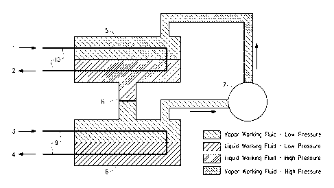
To illustrate how heat pumps operate, reference is made to the
Figures. A flooded evaporator heat pump is shown in Figure 1. In this
heat pump a first heat transfer medium, which is a warm liquid, which
21
CA 02820077 2013-06-04
WO 2012/082939
PCT/US2011/064974
comprises water, and, in some embodiments, additives, or other heat
transfer medium such as a glycol (e.g., ethylene glycol or propylene
glycol), enters the heat pump carrying heat from a low temperature
source, such as a building air handling system or warmed-up water from
condensers of a chiller plant flowing to the cooling tower, shown entering
at arrow 3, through a tube bundle or coil 9, in an evaporator 6, which has
an inlet and an outlet. The warm first heat transfer medium is delivered to
the evaporator, where it is cooled by liquid working fluid, which is shown in
the lower portion of the evaporator. The liquid working fluid evaporates at
a lower temperature than the warm first heat transfer medium which flows
through tube bundle or coil 9. The cooled first heat transfer medium re-
circulates back to the low temperature heat source as shown by arrow 4,
via a return portion of tube bundle or coil 9. The liquid working fluid,
shown in the lower portion of evaporator 6 in Figure 1, vaporizes and is
drawn into a compressor 7, which increases the pressure and temperature
of the working fluid vapor. The compressor compresses this vapor so that
it may be condensed in a condenser 5 at a higher pressure and
temperature than the pressure and temperature of the working fluid vapor
when it exits the evaporator. A second heat transfer medium enters the
condenser via a tube bundle or coil 10 in condenser 5 from a location
where high temperature heat is provided ("heat sink") such as a domestic
or service water heater or a hydronic heating system at arrow 1 in
Figure 1. The second heat transfer medium is warmed in the process and
returned via a return loop of tube bundle or coil 10 and arrow 2 to the heat
sink. This second heat transfer medium cools the working fluid vapor in
the condenser and causes the vapor to condense to liquid working fluid,
so that there is liquid working fluid in the lower portion of the condenser as
shown in Figure 1. The condensed liquid working fluid in the condenser
flows back to the evaporator through an expansion device 8, which may
be an orifice, capillary tube or expansion valve. Expansion device 8
reduces the pressure of the liquid working fluid, and converts the liquid
working fluid partially to vapor, that is to say that the liquid working fluid
flashes as pressure drops between the condenser and the evaporator.
Flashing cools the working fluid, i.e., both the liquid working fluid and the
22
CA 02820077 2013-06-04
WO 2012/082939
PCT/US2011/064974
working fluid vapor to the saturated temperature at evaporator pressure,
so that both liquid working fluid and working fluid vapor are present in the
evaporator.
In some embodiments the working fluid vapor is compressed to a
supercritical state and vessel 5 in Figure 1 represents a supercitical fluid
cooler where the working fluid vapor is cooled to a liquid state without
condensation.
In some embodiments the first heat transfer medium used in the
apparatus depicted in Figure 1 is chilled water returning from a building
113 where air conditioning is provided or from some other body to be
cooled.
Heat is extracted from the returning chilled water at the evaporator 6 and
the cooled chilled water is supplied back to the building or other body to be
cooled. In this embodiment the apparatus depicted in Figure 1 functions
to simultaneously cool the first heat transfer medium that provides cooling
to a body to be cooled (e.g. building air) and heat the second heat transfer
medium that provides heating to a body to be heated (e.g. domestic or
service water or process stream).
It is understood that the apparatus depicted in Figure 1 can extract
heat at the evaporator 6 from a wide variety of heat sources including
solar, geothermal and waste heat and supply heat from the condenser 5 to
a wide range of heat sinks.
It should be noted that for a single component working fluid
composition, the composition of the vapor working fluid in the evaporator
and condenser is the same as the composition of the liquid working fluid in
the evaporator and condenser. In this case, evaporation will occur at a
constant temperature. However, if a working fluid blend (or mixture) is
used, as in the present invention, the liquid working fluid and the working
fluid vapor in the evaporator (or in the condenser) may have different
compositions. This may lead to inefficient systems and difficulties in
servicing the equipment, thus a single component working fluid is more
desirable. An azeotrope or azeotrope-like composition will function
essentially as a single component working fluid in a heat pump, such that
23
CA 02820077 2013-06-04
WO 2012/082939
PCT/US2011/064974
the liquid composition and the vapor composition are essentially the same
reducing any inefficiencies that might arise from the use of a non-
azeotropic or non-azeotrope-like composition.
One embodiment of a direct expansion heat pump is illustrated in
Figure 2. In the heat pump as illustrated in Figure 2, first liquid heat
transfer medium, which is a warm liquid, such as warm water, enters an
evaporator 6' at inlet 14. Mostly liquid working fluid (with a small amount
of working fluid vapor) enters a coil 9' in the evaporator at arrow 3' and
evaporates. As a result, first liquid heat transfer medium is cooled in the
evaporator, and a cooled first liquid heat transfer medium exits the
evaporator at outlet 16, and is sent to a low temperature heat source (e.g.
warm water flowing to a cooling tower). The working fluid vapor exits the
evaporator at arrow 4' and is sent to a compressor 7', where it is
compressed and exits as high temperature, high pressure working fluid
vapor. This working fluid vapor enters a condenser 5' through a
condenser coil 10' at 1'. The working fluid vapor is cooled by a second
liquid heat transfer medium, such as water, in the condenser and becomes
a liquid. The second liquid heat transfer medium enters the condenser
through a condenser heat transfer medium inlet 20. The second liquid
heat transfer medium extracts heat from the condensing working fluid
vapor, which becomes liquid working fluid, and this warms the second
liquid heat transfer medium in the condenser. The second liquid heat
transfer medium exits from the condenser through the condenser heat
transfer medium outlet 18. The condensed working fluid exits the
condenser through lower coil 10' as shown in Figure 2 and flows through
an expansion device 12, which may be an orifice, capillary tube or
expansion valve. Expansion device 12 reduces the pressure of the liquid
working fluid. A small amount of vapor, produced as a result of the
expansion, enters the evaporator with liquid working fluid through coil 9'
and the cycle repeats.
In some embodiments the working fluid vapor is compressed to a
supercritical state and vessel 5' in Figure 2 represents a supercritical fluid
24
CA 02820077 2013-06-04
WO 2012/082939
PCT/US2011/064974
cooler where the working fluid vapor is cooled to a liquid state without
condensation.
In some embodiments the first heat transfer medium used in the
apparatus depicted in Figure 2 is chilled water returning from a building
where air conditioning is provided or from some other body to be cooled.
Heat is extracted from the returning chilled water at the evaporator 6' and
the cooled chilled water is supplied back to the building or other body to be
cooled. In this embodiment the apparatus depicted in Figure 2 functions
to simultaneously cool the first heat transfer medium that provides cooling
to a body to be cooled (e.g. building air) and heat the second heat transfer
medium that provides heating to a body to be heated (e.g. domestic or
service water or process stream).
It is understood that the apparatus depicted in Figure 2 can extract
heat at the evaporator 6' from a wide variety of heat sources including
solar, geothermal and waste heat and supply heat from the condenser 5'
to a wide range of heat sinks.
A centrifugal compressor uses rotating elements to accelerate the
working fluid radially, and typically includes an impeller and diffuser
housed in a casing. Centrifugal compressors usually take working fluid in
at an impeller eye, or central inlet of a circulating impeller, and accelerate
it radially outward. Some pressure rise occurs in the impeller, but most of
the pressure rise occurs in the diffuser section of the casing, where
velocity is converted to pressure. Each impeller-diffuser set is a stage of
the compressor. Centrifugal compressors are built with from 1 to 12 or
more stages, depending on the final pressure desired and the volume of
refrigerant to be handled.
The pressure ratio, or compression ratio, of a compressor is the ratio
of absolute discharge pressure to the absolute inlet pressure. Pressure
delivered by a centrifugal compressor is practically constant over a
relatively wide range of capacities. The pressure a centrifugal compressor
can develop depends on the tip speed of the impeller. Tip speed is the
speed of the impeller measured at its tip and is related to the diameter of
CA 02820077 2013-06-04
WO 2012/082939
PCT/US2011/064974
the impeller and its revolutions per minute. The tip speed required in a
specific application depends on the compressor work that is required to
elevate the thermodynamic state of the working fluid from evaporator to
condenser conditions. The volumetric flow capacity of the centrifugal
compressor is determined by the size of the passages through the
impeller. This makes the size of the compressor more dependent on the
pressure required than the volumetric flow capacity required.
Positive displacement compressors draw vapor into a chamber, and
the chamber volume is reduced to compress the vapor. After being
compressed, the vapor is forced from the chamber by further decreasing
the volume of the chamber to zero or nearly zero.
Reciprocating compressors use pistons driven by a crankshaft. They
can be either stationary or portable, can be single- or multi-staged, and
can be driven by electric motors or internal combustion engines. Small
reciprocating compressors from 5 to 30 hp are seen in automotive
applications and are typically for intermittent duty. Larger reciprocating
compressors up to 100 hp are found in large industrial applications.
Discharge pressures can range from low pressure to very high pressure
(greater than 5000 psi or 35 MPa).
Screw compressors use two meshed rotating positive-displacement
helical screws to force the gas into a smaller space. Screw compressors
are usually for continuous operation in commercial and industrial
application and may be either stationary or portable. Their application can
be from 5 hp (3.7 kW) to over 500 hp (375 kW) and from low pressure to
very high pressure (greater than 1200 psi or 8.3 MPa).
Scroll compressors are similar to screw compressors and include two
interleaved spiral-shaped scrolls to compress the gas. The output is more
pulsed than that of a rotary screw compressor.
Methods
In one embodiment is provided a method for producing heating
comprising condensing a vapor working fluid comprising (a)
26
CA 02820077 2013-06-04
WO 2012/082939
PCT/US2011/064974
E-CF3CH=CHF and (b) at least one compound of the formula C2H2F4; and
the weight ratio of E-CF3CH=CHF to the total amount of E-CF3CH=CHF
and C2H2F4 is from about 0.01 to 0.99 (e.g., from about 0.05 to about
0.82) in a condenser, thereby producing a liquid working fluid.
In one embodiment, the heating is produced in a high temperature
heat pump comprising the condenser, and the method further comprises
passing a heat transfer medium through the condenser (whereby said
condensation of working fluid heats the heat transfer medium) and passing
the heated heat transfer medium from the condenser to a body to be
heated.
A body to be heated may be any space, object or fluid that may be
heated. In one embodiment, a body to be heated may be a room,
building, or the passenger compartment of an automobile. Alternatively, in
another embodiment, a body to be heated may be another medium or heat
transfer fluid.
In one embodiment, the heat transfer medium is water and the body
to be heated is water. In another embodiment, the heat transfer medium
is water and the body to be heated is air for space heating. In another
embodiment, the heat transfer medium is an industrial heat transfer liquid
and the body to be heated is a chemical process stream.
In another embodiment, the method to produce heating further
comprises compressing the working fluid vapor in a centrifugal
compressor.
In one embodiment, the heating is produced in a heat pump
comprising the condenser, and the method further comprises passing a
fluid to be heated through the condenser, thus heating the fluid. In one
embodiment, the fluid is air, and the heated air from the condenser is
passed to a space to be heated. In another embodiment, the fluid is a
portion of a process stream, and the heated portion is returned to the
process.
27
CA 02820077 2013-06-04
WO 2012/082939
PCT/US2011/064974
In one embodiment of the method to produce heating, component (b)
is CHF2CHF2 and the weight ratio of E-CF3CH=CHF to the total amount of
E-CF3CH=CHF and CHF2CHF2 is less than 0.70 (e.g., at least about 0.05
but less than 0.70). In another embodiment of the method to produce
heating, component (b) is CHF2CHF2 and the weight ratio of E-
CF3CH=CHF to the total amount of E-CF3CH=CHF and CHF2CHF2 is from
about 0.01 to 0.69 (e.g., from about 0.05 to about 0.69). In another
embodiment of the method to produce heating, component (b) is
CHF2CHF2 and the weight ratio of E-CF3CH=CHF to the total amount of E-
CF3CH=CHF and CHF2CHF2 is from about 0.01 to 0.56 (e.g., from about
0.05 to about 0.56). In another embodiment, component (b) is CHF2CHF2
and the weight ratio of E-CF3CH=CHF to the total amount of E-
CF3CH=CHF and CHF2CHF2 is from about 0.01 to 0.53 (e.g., from about
0.05 to about 0.53). In another embodiment, component (b) is CHF2CHF2
and the weight ratio of E-CF3CH=CHF to the total amount of E-
CF3CH=CHF and CHF2CHF2 is from about 0.01 to 0.48 (e.g., from about
0.05 to about 0.48). In another embodiment, component (b) is CHF2CHF2
and the weight ratio of E-CF3CH=CHF to the total amount of E-
CF3CH=CHF and CHF2CHF2 is from about 0.01 to 0.39 (e.g., from about
0.05 to about 0.39). In another embodiment, component (b) is CHF2CHF2
and the weight ratio of E-CF3CH=CHF to the total amount of E-
CF3CH=CHF and CHF2CHF2 is from about 0.01 to 0.20 (e.g., from about
0.05 to about 0.20).
In another embodiment, component (b) is CHF2CHF2 and the weight
ratio of E-CF3CH=CHF to the total amount of E-CF3CH=CHF and
CHF2CHF2 is from about 0.09 to 0.99 (e.g., from about 0.09 to about 0.82
or from about 0.10 to about 0.82).
In some embodiments, the heat transfer medium may be selected
from water, glycol (such as ethylene glycol or propylene glycol). Of
particular note is an embodiment wherein the first heat transfer medium is
water and the body to be cooled is air for space cooling.
28
CA 02820077 2013-06-04
WO 2012/082939
PCT/US2011/064974
In another embodiment, the heat transfer medium may be an
industrial heat transfer liquid, wherein the body to be heated is a chemical
process stream, which includes process lines and process equipment
such as distillation columns. Of note are industrial heat transfer liquids
including ionic liquids, various brines such as aqueous calcium or sodium
chloride, glycols such as propylene glycol or ethylene glycol, methanol,
and other heat transfer media such as those listed in section 4 of the 2006
ASH RAE Handbook on Refrigeration.
In one embodiment, the method for producing heating comprises
extracting heat in a flooded evaporator heat pump as described above
with respect to Figure 1. In this method, the liquid working fluid is
evaporated to form a working fluid vapor in the vicinity of a first heat
transfer medium. The first heat transfer medium is a warm liquid, such as
water, which is transported into the evaporator via a pipe from a low
temperature heat source. The warm liquid is cooled and is returned to the
low temperature heat source or is passed to a body to be cooled, such as
a building. The working fluid vapor is then condensed in the vicinity of a
second heat transfer medium, which is a chilled liquid which is brought in
from the vicinity of a body to be heated (heat sink). The second heat
transfer medium cools the working fluid such that it is condensed to form a
liquid working fluid. In this method a flooded evaporator heat pump may
also be used to heat domestic or service water or a process stream.
In another embodiment, the method for producing heating comprises
producing heating in a direct expansion heat pump as described above
with respect to Figure 2. In this method, the liquid working fluid is passed
through an evaporator and evaporates to produce a working fluid vapor. A
first liquid heat transfer medium is cooled by the evaporating working fluid.
The first liquid heat transfer medium is passed out of the evaporator to a
low temperature heat source or a body to be cooled. The working fluid
vapor is then condensed in the vicinity of a second heat transfer medium,
which is a chilled liquid which is brought in from the vicinity of a body to
be
heated (heat sink). The second heat transfer medium cools the working
fluid such that it is condensed to form a liquid working fluid. In this
29
CA 02820077 2013-06-04
WO 2012/082939
PCT/US2011/064974
method, a direct expansion heat pump may also be used to heat domestic
or service water or a process stream.
In one embodiment of the method for producing heating, the heat
pump includes a compressor which is a centrifugal compressor.
In another embodiment of the invention is provided a method for
replacing HFC-134a working fluid in a heat pump designed for HFC-134a
comprising providing a replacement working fluid comprising (a) E-
CF3CH=CHF and (b) at least one compound of the formula C2H2F4;
provided that the weight ratio of E-CF3CH=CHF to the total amount of E-
CF3CH=CHF and C2H2F4 is from about 0.01 to 0.99 (e.g., from about 0.05
to about 0.82).
Of note for use in producing heating (including but not limited to as
replacements for other heat pump working fluids) are compositions
wherein component (b) is CHF2CHF2 and the weight ratio of E-
CF3CH=CHF to the total amount of E-CF3CH=CHF and CHF2CHF2 is from
about 0.1 to 0.2. Also of note are compositions wherein component (b) is
CHF2CHF2 and the weight ratio of E-CF3CH=CHF to the total amount of E-
CF3CH=CHF and CHF2CHF2 is from about 0.2 to 0.3. Also of note are
compositions wherein component (b) is CHF2CHF2 and the weight ratio of
E-CF3CH=CHF to the total amount of E-CF3CH=CHF and CHF2CHF2 is
from about 0.3 to 0.4. Also of note are compositions wherein component
(b) is CHF2CHF2 and the weight ratio of E-CF3CH=CHF to the total
amount of E-CF3CH=CHF and CHF2CHF2 is from about 0.4 to 0.5. Also of
note are compositions wherein component (b) is CHF2CHF2 and the
weight ratio of E-CF3CH=CHF to the total amount of E-CF3CH=CHF and
CHF2CHF2 is from about 0.5 to 0.6. Also of note are compositions
wherein component (b) is CHF2CHF2 and the weight ratio of E-
CF3CH=CHF to the total amount of E-CF3CH=CHF and CHF2CHF2 is from
about 0.6 to 0.7. Also of note are compositions wherein component (b) is
CHF2CHF2 and the weight ratio of E-CF3CH=CHF to the total amount of E-
CF3CH=CHF and CHF2CHF2 is from about 0.7 to 0.8. Also of note are
compositions wherein component (b) is CHF2CHF2 and the weight ratio of
CA 02820077 2013-06-04
WO 2012/082939
PCT/US2011/064974
E-CF3CH=CHF to the total amount of E-CF3CH=CHF and CHF2CHF2 is
from about 0.8 to 0.9.
Also of note for use in producing heating (including but not limited to
as replacements for other heat pump working fluids) are compositions
wherein component (b) is CF3CH2F and the weight ratio of E-CF3CH=CHF
to the total amount of E-CF3CH=CHF and CF3CH2F is from about 0.1 to
0.2. Also of note as replacements are compositions wherein component
(b) is CF3CH2F and the weight ratio of E-CF3CH=CHF to the total amount
of E-CF3CH=CHF and CF3CH2F is from about 0.2 to 0.3. Also of note as
replacements are compositions wherein component (b) is CF3CH2F and
the weight ratio of E-CF3CH=CHF to the total amount of E-CF3CH=CHF
and CF3CH2F is from about 0.3 to 0.4. Also of note are compositions
wherein component (b) is CF3CH2F and the weight ratio of E-CF3CH=CHF
to the total amount of E-CF3CH=CHF and CF3CH2F is from about 0.4 to
0.5. Also of note are compositions wherein component (b) is CF3CH2F
and the weight ratio of E-CF3CH=CHF to the total amount of E-
CF3CH=CHF and CF3CH2F is from about 0.5 to 0.6. Also of note are
compositions wherein component (b) is CF3CH2F and the weight ratio of
E-CF3CH=CHF to the total amount of E-CF3CH=CHF and CF3CH2F is
from about 0.6 to 0.7. Also of note are compositions wherein component
(b) is CF3CH2F and the weight ratio of E-CF3CH=CHF to the total amount
of E-CF3CH=CHF and CF3CH2F is from about 0.7 to 0.8. Also of note are
compositions wherein component (b) is CF3CH2F and the weight ratio of
E-CF3CH=CHF to the total amount of E-CF3CH=CHF and CF3CH2F is
from about 0.76 to 0.82 (e.g., from about 0.78 to about 82).
Also of note for use in producing heating (including but not limited to
as replacements for other heat pump working fluids) are compositions
wherein component (b) is a mixture of CHF2CHF2 and CF3CH2F, wherein
the weight ratio of CHF2CHF2 to CF3CH2F is at least about 1:4 (e.g., from
about 9:1 to about 1:4) and the weight ratio of E-CF3CH=CHF to the total
amount of E-CF3CH=CHF, CHF2CHF2 and CF3CH2F is from about 0.1 to
0.2. Also of note are compositions wherein component (b) is a mixture of
CHF2CHF2 and CF3CH2F, wherein the weight ratio of CHF2CHF2 to
31
CA 02820077 2013-06-04
WO 2012/082939
PCT/US2011/064974
CF3CH2F is at least about 1:4 (e.g., from about 9:1 to about 1:4) and the
weight ratio of E-CF3CH=CHF to the total amount of E-CF3CH=CHF,
CHF2CHF2 and CF3CH2F is from about 0.2 to 0.3. Also of note are
compositions wherein component (b) is a mixture of CHF2CHF2 and
CF3CH2F, wherein the weight ratio of CHF2CHF2 to CF3CH2F is at least
about 1:4 (e.g., from about 9:1 to about 1:4) and the weight ratio of E-
CF 3CH=CHF to the total amount of E-CF3CH=CHF, CHF2CHF2 and
CF3CH2F is from about 0.3 to 0.4. Also of note are compositions wherein
component (b) is a mixture of CHF2CHF2 and CF3CH2F, wherein the
weight ratio of CHF2CHF2 to CF3CH2F is at least about 1:4 (e.g., from
about 9:1 to about 1:4) and the weight ratio of E-CF3CH=CHF to the total
amount of E-CF3CH=CHF, CHF2CHF2 and CF3CH2F is from about 0.4 to
0.5. Also of note are compositions wherein component (b) is a mixture of
CHF2CHF2 and CF3CH2F, wherein the weight ratio of CHF2CHF2 to
CF3CH2F is at least about 1:4 (e.g., from about 9:1 to about 1:4) and the
weight ratio of E-CF3CH=CHF to the total amount of E-CF3CH=CHF,
CHF2CHF2 and CF3CH2F is from about 0.5 to 0.6. Also of note are
compositions wherein component (b) is a mixture of CHF2CHF2 and
CF3CH2F, wherein the weight ratio of CHF2CHF2 to CF3CH2F is at least
about 1:4 (e.g., from about 9:1 to about 1:4) and the weight ratio of E-
CF 3CH=CHF to the total amount of E-CF3CH=CHF, CHF2CHF2 and
CF3CH2F is from about 0.6 to 0.7. Also of note are compositions wherein
component (b) is a mixture of CHF2CHF2 and CF3CH2F, wherein the
weight ratio of CHF2CHF2 to CF3CH2F is at least about 1:4 (e.g., from
about 9:1 to about 1:4) and the weight ratio of E-CF3CH=CHF to the total
amount of E-CF3CH=CHF, CHF2CHF2 and CF3CH2F is from about 0.7 to
0.8. Of particular note for the compositions comprising both CHF2CHF2 to
CF3CH2F described above are compositions where the weight ratio of
CHF2CHF2 to CF3CH2F is from about 9:1 to about 1:1.25 (for example
1.25:1 to about 1:1.25).
In one embodiment of the method to replace HFC-134a, component
(b) is CHF2CHF2 and the weight ratio of E-CF3CH=CHF to the total
amount of E-CF3CH=CHF and CHF2CHF2 is from about 0.01 to 0.69 (e.g.,
32
CA 02820077 2013-06-04
WO 2012/082939
PCT/US2011/064974
from about 0.05 to about 0.69). In another embodiment of the method to
replace HFC-134a, component (b) is CHF2CHF2 and the weight ratio of E-
CF3CH=CHF to the total amount of E-CF3CH=CHF and CHF2CHF2 is from
about 0.01 to 0.56. In another embodiment, component (b) is CHF2CHF2
and weight ratio of E-CF3CH=CHF to the total amount of E-CF3CH=CHF
and CHF2CHF2 is from about 0.01 to 0.53 (e.g., from about 0.05 to about
0.53). In another embodiment, component (b) is CHF2CHF2 and the
weight ratio of E-CF3CH=CHF to the total amount of E-CF3CH=CHF and
CHF2CHF2 is from about 0.01 to 0.48 (e.g., from about 0.05 to about 0.48).
In another embodiment, component (b) is CHF2CHF2 and the weight ratio
of E-CF3CH=CHF to the total amount of E-CF3CH=CHF and CHF2CHF2 is
from about 0.01 to 0.39 (e.g., from about 0.05 to about 0.39). In another
embodiment, component (b) is CHF2CHF2 and the weight ratio of E-
CF3CH=CHF to the total amount of E-CF3CH=CHF and CHF2CHF2 is from
about 0.01 to 0.20 (e.g., from about 0.05 to about 0.20).
In another embodiment, component (b) is CHF2CHF2 and the weight
ratio of E-CF3CH=CHF to the total amount of E-CF3CH=CHF and
CHF2CHF2 is from about 0.09 to 0.99 (e.g., from about 0.10 to about
0.85).
In this method of replacing HFC-134a, the compositions disclosed
herein are useful in centrifugal heat pumps that may have been originally
designed and manufactured to operate with HFC-134a.
In replacing HFC-134a with the compositions as disclosed herein in
existing equipment, additional advantages may be realized by making
adjustments to equipment or operating conditions or both. For example,
impeller diameter and impeller speed may be adjusted in a centrifugal heat
pump where a composition is being used as a replacement working fluid.
In one embodiment, the method of replacing HFC-134a further
comprises increasing the rotational speed of the impeller of the centrifugal
compressor in order to better match the heat pump heating rate (and in
some instances both heating and cooling rates) achieved with the HFC-
134a working fluid. Increasing rotational speed of the impeller increases
33
CA 02820077 2013-06-04
WO 2012/082939
PCT/US2011/064974
the working fluid circulation rate and the resulting heating and cooling
rates.
Alternatively, in another embodiment, the method of replacing HFC-
134a further comprises replacing the centrifugal compressor impeller with
an impeller of larger diameter in order to better match the heating and
cooling rates achieved with the HFC-134a working fluid.
Alternatively, in this method of replacing HFC-134a, the compositions
as disclosed herein may be useful in new heat pump equipment. In such
new equipment, a centrifugal compressor and the evaporators and
condensers used therewith, may be used. New equipment may be
designed and optimized for use with the working fluids of the present
invention.
In another embodiment of the present invention is provided a method
for raising the maximum feasible condenser operating temperature in a
heat pump apparatus suitable for use with HFC-134a working fluid relative
to the maximum feasible condenser operating temperature when HFC-
134a is used as the heat pump working fluid, comprising charging the heat
pump with a working fluid comprising (a) E-CF3CH=CHF and (b) at least
one compound of the formula C2H2F4; provided that the weight ratio of E-
CF3CH=CHF to the total amount of E-CF3CH=CHF and C2H2F4 is from
about 0.01 to 0.99 (e.g., from about 0.05 to about 0.82 or from about 0.05
to about 0.80).
In some embodiments, when HFC-134a is used as the working fluid
in a heat pump, the maximum feasible condenser operating temperature
ranges from about 65 to about 75 C. In another embodiment the
maximum feasible operating temperature ranges from about 70 to about
75 C. In one embodiment, the maximum feasible condenser operating
temperature is about 71 C when 134a is used as the heat pump working
fluid.
In one embodiment of the method to raise the maximum feasible
condenser operating temperature, when a composition comprising E-
34
CA 02820077 2013-06-04
WO 2012/082939
PCT/US2011/064974
CF3CH=CHF and CHF2CHF2, is used as the heat pump working fluid, the
maximum feasible condenser operating temperature is raised at least
about 5 C as compared to the maximum feasible condenser operating
temperature when HFC-134a is used as the heat pump working fluid.
In another embodiment of the method to raise the maximum feasible
condenser operating temperature, when a composition comprising E-
CF3CH=CHF and CHF2CHF2, is used as the heat pump working fluid, the
maximum feasible condenser operating temperature is raised at least
about 10 C as compared to the maximum feasible condenser operating
temperature when HFC-134a is used as the heat pump working fluid.
In one embodiment, the maximum feasible condenser operating
temperature, when the working fluid comprises E-CF3CH=CHF to
CHF2CHF2, is raised to at least about 84 C in currently available
compressors. The maximum feasible condenser operating temperature,
when the working fluid comprises E-CF3CH=CHF to CHF2CHF2, is raised
to at least about 81 C in currently available compressors.
In one embodiment, the maximum feasible condenser operating
temperature, when the working fluid comprises E-CF3CH=CHF to
CHF2CHF2, is raised to a temperature ranging from about 75 to about
80 C in currently available compressors.
In another embodiment, the maximum feasible condenser operating
temperature, when the working fluid comprises E-CF3CH=CHF to
CHF2CHF2, is raised to a temperature ranging from about 80 to about
85 C in currently available compressors.
In another embodiment, the maximum feasible condenser operating
temperature, when the working fluid comprises E-CF3CH=CHF to
CHF2CHF2, is raised to a temperature ranging from about 81 to about
84 C in currently available compressors.
In one embodiment, the maximum feasible condenser operating
temperature, when the working fluid comprises E-CF3CH=CHF to
CHF2CHF2, is raised to at least about 84 C in currently available
CA 02820077 2013-06-04
WO 2012/082939
PCT/US2011/064974
compressors. In another embodiment, the maximum feasible condenser
operating temperature, when the working fluid comprises E-CF3CH=CHF
to CHF2CHF2, is raised to at least about 81 C in currently available
compressors.
In one embodiment of the method to raise the maximum condenser
operating temperature, component (b) is CHF2CHF2 and the weight ratio
of E-CF3CH=CHF to the total amount of E-CF3CH=CHF and CHF2CHF2
wherein component (b) is CHF2CHF2 and the weight ratio of E-
CF3CH=CHF to the total amount of E-CF3CH=CHF and CHF2CHF2 is less
than 0.70 (e.g., at least about 0.05 but less than 0.70). In another
embodiment of the method to raise the maximum condenser operating
temperature, component (b) is CHF2CHF2 and the weight ratio of E-
CF3CH=CHF to the total amount of E-CF3CH=CHF and CHF2CHF2 is from
about 0.01 to 0.69 (e.g., from about 0.05 to about 0.69). In another
embodiment of the method to raise the maximum condenser operating
temperature, component (b) is CHF2CHF2 and the weight ratio of E-
CF3CH=CHF to the total amount of E-CF3CH=CHF and CHF2CHF2 is from
about 0.01 to 0.56. In another embodiment, component (b) is CHF2CHF2
and the weight ratio of E-CF3CH=CHF to the total amount of E-
n CF3CH=CHF and CHF2CHF2 is from about 0.01 to 0.53 (e.g., from about
0.05 to about 0.53). In another embodiment, component (b) is CHF2CHF2
and the weight ratio of E-CF3CH=CHF to the total amount of E-
CF3CH=CHF and CHF2CHF2 is from about 0.01 to 0.48. In another
embodiment, component (b) is CHF2CHF2 and the weight ratio of E-
CF3CH=CHF to the total amount of E-CF3CH=CHF and CHF2CHF2 is from
about 0.01 to 0.39. In another embodiment, component (b) is CHF2CHF2
and the weight ratio of E-CF3CH=CHF to the total amount of E-
CF3CH=CHF and CHF2CHF2 is from about 0.01 to 0.20. In another
embodiment, component (b) is CHF2CHF2 and the weight ratio of E-
CF3CH=CHF to the total amount of E-CF3CH=CHF and CHF2CHF2 is from
about 0.09 to 0.99 (e.g., from about 0.09 to about 0.82).
36
CA 02820077 2013-06-04
WO 2012/082939
PCT/US2011/064974
EXAMPLES
The concepts disclosed herein will be further described in the
following examples, which do not limit the scope of the invention described
in the claims.
Example 1: Heating Performance for compositions containing
E-HF0-1234ze and HFC-134
The performance of compositions containing trans-HF0-1234ze and
HFC-134 in a centrifugal water heating heat pump is determined and
compared to performance for HFC-134a. The data are shown in Table 1.
The data are based on the following conditions:
Evaporator temperature 26.7 C
Condenser temperature 80.0 C
Compressor efficiency 70%
TABLE 1
E-HFO-
1234ze/
E-HFO- 1234ze/
Variable HFC-134a HFC-134
HFC-134 vs 134a
(40/60 wt%)
(A%)
Liquid subcooling, C 11.11 11.11
Vapor superheat, C 0.00 0.00
Pressure (condenser), kPa 2,642.90 2,168.57 -
17.95
Pressure (evaporator), kPa 698.46 565.23 -19.07
Compressor Discharge
95.60 92.10 -3.66
Temperature, C
Condenser Glide, C 0.01
Evaporator Glide, C 0.00
Net Refrig, kJ/kg 113.38 118.82 4.80
Compressor Work, kJ/kg 39.19 39.20 0.03
COP for Heating 3.893 4.031 3.54
Volumetric Heating
5,048.45 4,306.96 -14.69
Capacity, kJ/rn3
GWP* 1430 662 -53.71
The data indicate that the condenser pressure for the new blend is
within the range for some currently available compressors. However, the
37
CA 02820077 2013-06-04
WO 2012/082939
PCT/US2011/064974
condenser pressure for HFC-134a exceeds the pressure for some
currently available compressors. Compressor work is very close to that for
HFC-134a, and therefore the tip speed will be similar and the composition
will provide a near drop-in replacement for HFC-134a. Temperature glide
for the new blend is negligible, allowing more efficient heat transfer at the
heat exchangers and making the blend feasible for use in flooded
evaporators. Higher COP for the new blend demonstrates improved
energy efficiency relative to HFC-134a. Additionally, the GWP for the new
blend is less than half that for HFC-134a.
Note that the GWP for the pure components are taken from:
= "Climate Change 2007 ¨ IPCC (Intergovernmental Panel on
Climate Change) Fourth Assessment Report on Climate Change",
from the section entitled "Working Group 1 Report: "The Physical
Science Basis", Chapter 2, pp. 212-213, Table 2.14.
= Papadimitriou et al., Physical Chemistry Chemical Physics, 2007,
vol. 9, pp. 1-13.
= Javadi et al., Atmospheric Chemistry and Physics Discussions 8,
1069-1088, 2008).
= Specifically, the 100 year time horizon GWP values are used.
The GWP values for compositions containing more than one
component are calculated as weighted averages of the individual
component GWP values.
Example 2: Heating Performance for compositions containing
E-HF0-1234ze and HFC-134
The performance of compositions containing E-HF0-1234ze and
HFC-134 in a centrifugal water heating heat pump is determined and
compared to performance for HFC-134a. The data are shown in Table 2.
The data are based on the following conditions:
Evaporator temperature 26.7 C
Condenser temperature 80.0 C
Compressor efficiency 70%
38
CA 02820077 2013-06-04
WO 2012/082939
PCT/1JS2011/064974
TABLE 2
E-HFO- E-HFO-
1234ze/
1234ze/ HFC-
Variable HFC-134a HFC-134
134
vs 134a
(65/35 wt%)
(%.A)
Liquid subcooling, C 11.11 11.11
Vapor superheat, C 0.00 0.00
Pressure (condenser), kPa 2,643 2125 -19.61
Pressure (evaporator), kPa 698.46 556.0 -20.40
Compressor Discharge
95.60 91.02 -4.79
Temperature, C
Condenser Glide, C .08
Evaporator Glide, C .05
Net Refrig, kJ/kg 113.4 112.8 -0.52
Compressor Work, kJ/kg 39.19 37.64 -3.96
COP for Heating 3.893 3.996 2.65
Volumetric Heating
5,048 4163 -17.54
Capacity, kJ/m3
GWP* 1430 389 -72.80
The data indicate that the condenser pressure for the new blend is
within the range for some currently available compressors. However, the
condenser pressure for HFC-134a exceeds the pressure for some
currently available compressors. Temperature glide for the new blend is
low, making the blend feasible for use in flooded evaporators. Higher
COP for the new blend demonstrates improved energy efficiency relative
to HFC-134a. Additionally, the GWP for the new blend is significantly
reduced relative to the GWP of HFC-134a.
Example 3: Simultaneous Heating and Cooling Performance
for compositions containing 20 weight percent trans-HF0-1234ze and 80
weight HFC-134
The apparatus described in Figures 1 and 2 can be used to
simultaneously provide hot water for domestic use and chilled water for air
conditioning. The performance of compositions containing trans-HFO-
1234ze and HFC-134 in a centrifugal machine that provides heating and
39
CA 02820077 2013-06-04
WO 2012/082939 PCT/US2011/064974
cooling simultaneously is determined and compared to performance for
HFC-134a. The data are shown in Table 3. The data are based on the
following conditions:
Evaporator temperature 4.4 C
Condenser temperature 80 C
Compressor efficiency 70%
TABLE 3
E-HF0-1234ze/
E-HFO- HFC-134
1234ze/
HFC-134a (20/80 wt%) vs
HFC-134 HFC-134a
(20/80 wt%)
(%A)
HF0-1234ze-E
(CF3CH=CHF)
HFC-134 (CHF2CHF2) 80
GWP 1430 881.2 -38.38
Liquid subcooling, C 10 10
Vapor superheat, C 0 0
Pressure (condenser) 2643 2176 -17.68
Pressure (evaporator) 342.6 271.6 -20.74
Compressor Discharge
102.6 100.4
Temperature, C
Condenser Glide, C 0 0
Evaporator Glide, C 0 0.02
Net Refrigeration, kJ/kg 98.02 108.94 11.14
Compressor Work, kJ/kg 61.21 63.08 3.06
COP for Cooling 1.602 1.727 7.80
Volumetric Cool
1614 1427 -11.60
Capacity, kJ/m3
COP for Heating 2.60 2.73 4.80
Volumetric Heating
2622 2253 -14.07
Capacity, kJ/m3
Total COP 4.20 4.45 5.95
The data indicate that this mode of operation is possible with the new
blend while it is not with HFC-134a, because the condenser pressure
113 would exceed the maximum feasible value The new blend provides low
temperature glide, thus allowing use with flooded evaporators. The
CA 02820077 2013-06-04
WO 2012/082939 PCT/US2011/064974
compressor work for the new blend is comparable to that with HFC-134a
thus the tip speed of the centrifugal compressor impeller will be similar
making the new blend a suitable replacement for HFC-134a. The COP for
both cooling and heating for the new blend shows improvement over that
for HFC-134a.
Example 4: Simultaneous Heating and Cooling Performance
for compositions containing 60 weight percent trans-HF0-1234ze and 40
weight percent HFC-134
The apparatus described in Figures 1 and 2 can be used to
simultaneously provide hot water for domestic use and chilled water for air
conditioning. The performance of compositions containing trans-HFO-
1234ze and HFC-134 in a centrifugal machine that provides heating and
cooling simultaneously is determined and compared to performance for
HFC-134a. The data are shown in Table 4. The data are based on the
following conditions:
Evaporator temperature 4.4 C
Condenser temperature 80 C
Compressor efficiency 70%
TABLE 4
E-HF0-1234ze/
E-HFO- HFC-134
1234ze/
HFC-134a (60/40 wt%) vs
HFC-134 HFC-134a
(60/40 wt%)
(%A)
HF0-1234ze-E
(CF3CH=CHF)
HFC-134 (CHF2CHF2) 40
GWP 1430 443.6 -75.88
Liquid subcooling, C 10 10
Vapor superheat, C 0 0
Pressure (condenser) 2643 2138 -21.02
Pressure (evaporator) 342.6 271.4 -22.87
Compressor Discharge 102.6 97.36
Temperature, C
Condenser Glide, C 0 0.07
41
CA 02820077 2013-06-04
WO 2012/082939 PCT/US2011/064974
E-HF0-1234ze/
E-HFO-
HFC-134
1234ze/
HFC-134a (60/40 wtlY0) vs
HFC-134
HFC-134a
(60/40 wt lo)
(%A)
Evaporator Glide, C 0 0.02
Net Refrigeration, kJ/kg 98.02 98.12 0.11
Compressor Work, kJ/kg 61.21 58.83 -4.28
COP for Cooling 1.602 1.668 4.53
Volumetric Cool
1614 1348 -18.10
Capacity, kJ/m3
COP for Heating 2.602 2.668 2.79
Volumetric Heating
2622 2157 -19.50
Capacity, kJ/m3
Total COP 4.204 4.336 3.45
The data indicate that this mode of operation is possible with the new
blend while it is not with HFC-134a. The new blend provides negligible
temperature glide, thus allowing use with flooded evaporators. The
compressor work is comparable to that of 134a thus the tip speed of the
centrifugal compressor impeller will be similar making it a near drop in
replacement for HFC-134a. The COP for both cooling and heating for the
new blend shows substantial improvement over that for HFC-134a.
Example 5: Flammability testing of
compositions containing E-CF3CH=CHF and CHF2CHF2
A composition containing 70 weight percent E-CF3CH=CHF
(E-HF0-1234ze) and 30 weight percent CHF2CHF2 (HFC-134) was tested
according to the ASTM E681- 2001 test procedure at a temperature of
60 C and was found to be flammable. A composition containing 69.75
weight percent E-CF3CH=CHF (E-HFC-1234ze) and 30.25 weight percent
CHF2CHF2 (HFC-134) was tested under the same conditions and was
found to be non-flammable.
42
CA 02820077 2013-06-04
WO 2012/082939 PCT/US2011/064974
Example 6: Flammability testing of
compositions containing E-CF2CH=CHF and CF3CH2F
A composition containing 82.5 weight percent E-CF3CH=CHF
(E-HF0-1234ze) and 17.5 weight percent CF3CH2F (HFC-134a) was
tested according to the ASTM E681- 2001 test procedure at a temperature
of 60 C and was found to be flammable. A composition containing 81.3
weight percent E-CF3CH=CHF) and 18.7 weight percent CF3CH2F was
tested under the same conditions and was found to be flammable with a
single value for UFL and LFL. A composition containing 80 weight percent
E-CF3CH=CHF) and 20 weight percent CF3CH2F was tested under the
same conditions and was found to be non-flammable. A composition
containing 81.25 weight percent E-CF3CH=CHF) and 18.75 weight percent
CF3CH2F was tested under the same conditions and was found to be non-
flammable.
Example 7: Heating Performance for compositions containing
E-HF0-1234ze and HFC-134a
The performance of compositions containing E-HF0-1234ze and
HFC-134a in a centrifugal water heating heat pump is determined and
compared to performance for neat HFC-134a. The data are shown in
Table 5. The data are based on the following conditions:
Evaporator temperature 26.7 C
Condenser temperature 80.0 C
Compressor efficiency 70%
TABLE 5
E-HF0-1234ze/
E-HF0-1234ze/ HFC-134a
Variable units HFC-134a HFC-134a vs 134a
(75/25 wt%)
(%A)
Liquid subcooling, C C 11.11 11.11
Vapor superheat, C C 0.00 0.00
Pressure (condenser), kPa kPa 2,643 2,196.47 -16.89
Pressure (evaporator), kPa kPa 698.46 576.90 -
17.40
43
CA 02820077 2013-06-04
WO 2012/082939 PCT/US2011/064974
E-HF0-1234ze/ E-HF0-1234ze/HFC-134a
Variable units HFC-134a HFC-134a vs 134'
(75/25 wt%)
(%A)
Compressor Discharge C
Temperature, C 95.60 91.35
Condenser Glide, C C 0.51
Evaporator Glide, C C 0.42
Net Refrigeration, kJ/kg kJ/kg 113.4 107.51 -5.19
Compressor Work, kJ/kg kJ/kg 39.19 36.58 -6.66
COP for Heating 3.893 3.939 1.18
Volumetric Heating
kJ/m3
Capacity, kJ/m3 5,048 4217.90 -16.44
GWP* 1430 362 -74.69
The data indicate that the condenser pressure for the new blend is
within the range for some currently available compressors. However, the
condenser pressure for HFC-134a exceeds the pressure for some
currently available compressors. Temperature glide for the new blend is
non-negligible but relatively low, making the blend feasible for use in
flooded evaporators. Higher COP for the new blend demonstrates
improved energy efficiency relative to HFC-134a. Additionally, the GWP
for the new blend is significantly reduced relative to the GWP of
HFC-134a.
44