Note: Descriptions are shown in the official language in which they were submitted.
CA 02820581 2013-05-07
WO 2012/061883
PCT/AU2011/001443
1
A COUPLING APPARATUS FOR HIGH POWER ELECTRICAL
CONNECTORS
TECHNICAL FIELD
The present invention relates to an apparatus for assisting in the
connecting together of electrical connectors for very heavy duty cables.
BACKGROUND
The discussion of any prior art documents, techniques, methods or
apparatus is not to be taken to constitute any admission or evidence that
such prior art forms, or ever formed, part of the common general
knowledge.
Very heavy duty electrical cables are found in a number of contexts
including mining. These cables are capable of meeting the very high
power requirements of large electrical machines. For example, cables
capable of carrying 800 Amp currents at 22,000V may be used in such
environments.
The cables are typically terminated with specially made electrical
connectors. In order to join one length of cable to another the
corresponding end connectors must be appropriately manipulated so that
25* they can be interconnected.
=
However, cables of this type are very heavy and have little flexibility. For
example, heavy duty power cables used in underground or open cut mines
' are frequently made with lead insulation and steel wire armor over copper
conductors. In order to manipulate the cables so that they can be
interconnected a number of workers are typically required to lift and align
the cables and connectors.
CA 02820581 2013-05-07
PCIYAU2011/001443
. Received
30/08/2012
=
2 ,
It will be realized that this presents a laborious and time intensive job
which has the
potential to injure to workers.
Furthermore, the workers have been known to inadvertently rupture the
electrical
connection inside a connector so that once the connectors are interconnected,
correct
functionality of the joined cables is lost.
It is an object of the present invention to provide an apparatus that
addresses one or
more of the above-described problems.
SUMMARY OF THE INVENTION
According to a first aspect of the present invention there is provided a
coupler to
interconnect first and second connector assemblies of respective first and
second
electrical cables and able to be released from the cables after
interconnection, the
coupler including:
a first retaining assembly to Main the first connector;
a second retaining assembly to retain the second connector with the first
connector;
a translation assembly for relative motion of said first assembly and said
second
assembly toward each other to thereby mate the first connector with the second
connector.
Preferably at least one of the first and second retaining assemblies includes
an
arrangement for rotation of at least one of the first or second connector.
Preferably the translation assembly is arranged to move at least one, or both,
of the first
and second retaining assemblies toward each other.
In the preferred embodiment the first retaining assembly includes the
arrangement for
rotation of the first connector.
AMENDED SHEET
WEA/AU
CA 02820581 2013-05-07
WO 2012/061883
PCT/AU2011/001443
3
In a further embodiment of the invention the second retaining assembly is
also arranged to rotate the second connector assembly.
In the first embodiment the translation assembly is arranged to move the
second retaining assembly toward the first retaining assembly.
Preferably the first retaining assembly comprises a first yoke for retaining
the first retaining assembly. The first yoke may be formed in opposing
parts which can be opened to receive the first connector assembly. In a
preferred embodiment the opposing parts define a receptacle for a sleeve,
or as it may be called an "adaptor", which holds the first connector in use.
A power actuator is preferably provided to open and close the first yoke.
=
Preferably a drive train is provided for rotating the sleeve within the yoke.
The drive drain may include a drive pinion arranged to mesh with teeth
formed about the sleeve.
Preferably the sleeve is formed of a resilient material such as -
polypropylene or polyurethane or nylon to thereby cushion the connector.
In a first embodiment the drive chain is driven by a wheel for rotation by an
operator. Alternatively, the drive chain may be driven by a motor.
Preferably the second retaining assembly comprises a second yoke for
retaining the second connector assembly. The second yoke may be
formed in opposing parts which can be opened to receive the first
connector. In a preferred embodiment the opposing parts define a
receptacle for a sleeve or "adaptor" which holds the second connector in
use.
CA 02820581 2013-05-07
WO 2012/061883
PCT/AU2011/001443
4
In the preferred embodiment the opposing parts of the second yoke are
hingedly connected by a pivot pin so that a first part of the first yoke may
be pivoted away from a second part of the second yoke.
A power actuator is preferably provided to open and close the second
yoke.
The translation assembly may comprise a rack and pinion arrangement
associated with the second retaining assembly.
Preferably the first retaining assembly and the second retaining assembly
are mounted upon a common frame.
In a first embodiment the rack is fast with the frame and the pinion is fast
with the second retaining assembly. In the first embodiment the pinion is
coupled to a drive wheel for rotation by an operator.
In a second embodiment the first retaining assembly and the second
retaining assembly are brought towards each other by means of powered
actuators. For example, the powered actuators may comprise hydraulic
rams arranged to slide the first retaining assembly and the second retaining
assembly along members of the frame.
Preferably cable supports are mounted adjacent the first retaining
assembly and the second retaining assembly for supporting respective
cables of the first connector and the second connector.
The cable supports may comprise rotatable sheaves.
Preferably cable guides are provided for assisting in directing cables of the
connector assemblies to respective cable supports during use.
Preferably respective powered risers are provided at opposite sides of the
apparatus for lifting of the first cable and the second cable to assist in
CA 02820581 2013-05-07
WO 2012/061883
PCT/AU2011/001443
installing and removing the connector assemblies to and from the retaining
assemblies. The powered risers preferably include telescopic arms
coupled to power actuators.
5 Preferably the telescopic arms include pulleys through which lines run
for
attachment to the connector assemblies for lifting thereof.
In a preferred embodiment the frame is coupled to the stand via a linkage
including a pivot for tilting the frame relative to the stand so that the
first
and second retaining assemblies may be tilted down to reduce the height
through which connectors must be lifted for installation in the first and
second retaining assemblies.
In an embodiment of the invention designed for use on sloping ground, as
may be found in underground mines for example, the frame is pivotally
mounted to a stand so that the frame may be rolled through a first angle
relative to the stand. The stand may comprise a platform or a "basket" for
an operator to stand in while using the coupling apparatus.
Preferably a motor is provided to adjust a pivot angle between the frame
and the stand so that the frame may be kept at a desired angle, for
example horizontal, irrespective of the slope of the surface supporting the
stand.
According to a further aspect of the present invention there is provided an
adaptor for an electrical connector comprising:
at least first and second parts defining a space for snugly receiving
an electrical connector therein; and
an external surface for forcing by a rotation member.
In a first embodiment the at least first and second parts comprise two
portions that are detachably interlocked.
CA 02820581 2013-05-07
WO 2012/061883
PCT/AU2011/001443
6
Preferably the external surface is formed for meshing with gears of a pinion
to thereby impart rotation.
BRIEF DESCRIPTION OF THE DRAWINGS
The Detailed Description is not to be regarded as limiting the scope of the
preceding Summary of the Invention in any way. The Detailed Description
will make reference to a number of drawings as follows:
Figure 1 is a side view of a coupling apparatus according to a first
embodiment of the present invention.
Figure 2 is an end view of the coupling apparatus of Figure 1.
Figure 3 is a top plan view of the coupling apparatus of Figure 1.
Figure 4 is a perspective view of a sleeve or adaptor according to a first
embodiment of an aspect of the present invention.
Figure 5A is a side view of the adaptor of Figure 4.
Figure 5B is a front plan view of the adaptor of Figure 4.
Figure 50 is a cross-section through the adaptor of Figure 4.
Figure 6 is a perspective view of a cradle according to an embodiment of
an aspect of the present invention in use.
Figure 7 is an isometric view of a coupling apparatus according to a further
embodiment of the present invention.
Figure 8 is a side plan view of the coupling apparatus of Figure 7.
CA 02820581 2013-05-07
WO 2012/061883
PCT/AU2011/001443
7
Figure 9 is a top plan view of the coupling apparatus of Figure 7.
Figure 10 is an end view of the coupling apparatus of Figure 7.
Figure 11 is an end view of the coupling apparatus of Figure 7 in a tilted
configuration with retracted arms.
Figure 12 is an end view of the coupling apparatus of Figure 7 in a tilted
configuration with extended arms.
Figure 13 is a non-planar view of the coupling apparatus of Figure 7 in use
during the raising of a connector assembly.
Figu're 14 is an end view of the coupling apparatus of Figure 7. in a non-
15. tilted configuration with open yokes.
Figure 15 is an isometric view of a coupling apparatus according to a
further embodiment of the invention intended primarily for use in
underground mines.
Figure 16 is a top plan view of a slight variation of the coupling apparatus
of Figure 15 wherein a gate has been replaced with a vehicle mounting
= bracket.
Figure 17 is a side view of the coupling apparatus of Figure 16.
Figure 18 is a view of the coupling apparatus of Figure 16 wherein the
coupling assembly has been rolled anti-clockwise relative to resting
position.
Figure 19 is a view of the coupling apparatus of Figure 16 wherein the
coupling assembly has been rolled clockwise relative to resting position.
CA 02820581 2013-05-07
WO 2012/061883
PCT/AU2011/001443
8
Figure 20 is a top planar view of a coupling apparatus according to an
embodiment of the invention inCluding two rotation assemblies for rotating
yokes of the apparatus.
Figure 2 comprises various views of a second embodiment of a coupler
according to the present invention.
Figure 3 illustrates a connector sleeve and drive sprocket used in the
various embodiments of the invention.
Preferred features, embodiments and variations of the invention may be
discerned from the following Detailed Description which provides sufficient
information for those skilled in the art to perform the invention.
DETAILED DESCRIPTION OF PREFERRED EMBODIMENTS
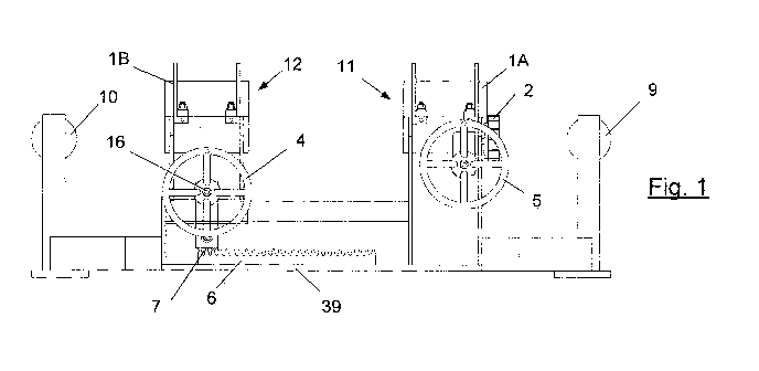
Figures 1, 2 and 3 are side, end and top plan views of a coupling apparatus
or "coupler" according to a first embodiment of the present invention.
The coupler includes a frame 39 upon which are mounted a first retaining
assembly 11 and a second retaining assembly 12 for retaining respective
connector assemblies. The retaining assemblies may be brought relatively
toward and away from each other by a translation assembly which
comprises a rack 6 mounted to the frame and which meshes with a pinion
7. The pinion 7 is coupled to a drive train of the second retaining assembly
which is driven by an axle 16, to one end of which there is mounted a
wheel 4. Accordingly, upon a worker rotating wheel 4 the second retaining
assembly 12 may be brought toward and away from the first retaining
assembly 11.
With reference to the end view of Figure 2, each of the retaining
assemblies 11, 12 includes a yoke 1A, 1B which has an upper part that can
be pivoted about a shaft 3 in order to open the yoke.
CA 02820581 2013-05-07
WO 2012/061883
PCT/AU2011/001443
9
A connector adaptor in the form of a split sleeve 31, as shown in Figures 4
and 5A to 5C can then be inserted into the open yoke. The sleeve is
formed of two interlocking and detachable parts that cooperate to define a
space shaped to snugly retain the connector. Since the sleeve is
preferably made of a synthetic material, e.g. polypropylene or polyurethane
or nylon, it prevents metal-to-metal contact between the connector and the
inner ring of the yoke 1. It will be realized that a number of sleeves 31 may
be made, all having the same outer configuration, but with different inner.
configurations to accommodate the profile's of different types of connectors.
=
Consequently, the sleeve 31 comprises an adaptor between different
shaped electrical connectors and the coupling apparatus.
The first retaining assembly 11 is fitted with an arrangement for rotation of
the sleeve including pinion 2. The pinion meshes with teeth 32 formed on
the outside of the sleeve 31. The pinion 2 is coupled to a drive wheel 5 by
a drive train associated with the first retaining assembly 11. Consequently,
upon a worker rotating wheel 5, the pinion 2 is 'rotated which in turn rotates
the sleeve 31 within yoke 1.
In the presently described embodiment, there is no such drive train for
rotating the sleeve retained in the second retaining assembly 12 although
in other embodiments of the invention both retaining assemblies may
incorporate an arrangement to rotate their respective sleeves. Similarly, in
other embodiments of the invention both of the retaining assemblies may
be moved back and forth along the frame.
Cable supports in the form of sheaves 9 and 10 are provided at opposing
ends of the frame 39 to support respective cables of the first connector and
the second connector. The cable supports help to reduce strain between
the internal connection of the cables and the connectors. As previously
mentioned, the cable supports 9 and 10 include sheaves or rollers to
support the cables.
=
CA 02820581 2013-05-07
WO 2012/061883 PCT/AU2011/001443
=10
The cable supports 9 and 10 assist workers in installing the connectors into
the yokes of the first and second retaining assemblies.
In use first and second adaptors 31 are initially fitted around each of the
opposing connector assemblies that are to be coupled together. The
adaptors 31 are then lifted into the yokes 1A and 1B which have previously
opened to receive them. The yokes are then closed so that teeth 32 of
adaptor 31 meshes with pinion 2 in the case of retaining assembly 11. The
cables from each of the connectors are located over sheaves 9 and 10. An
operator then turns wheels 4 and 5 in order to bring the connectors
=
together and orientate them so that they are aligned to be mated together.
Once mated together the connectors, with sleeves 31 still about them can
be bolted together and lifted from the yokes onto a frame 34 as shown in
Figure 6 where the cables 36 and bolts 38 can also be seen.
Referring now to Figures 7 to 10, there are shown isometric, rear, top .and
end views of a coupling apparatus 64 according to a second embodiment
of the invention which is preferred for use in outside environments such as
open-cut mines.
Coupler 64 is intended to be mounted to a vehicle by means of brackets 60
and 62 so that it may be moved to a location on site where it is required.
Coupler 64 is fitted with substantially more power actuators, such as =
hydraulic rams and motors, than that of the embodiment of Figure 1. The
various hydraulic rams and motors are hydraulically powered by the vehicle
to which it is mounted.
A motor 55 is provided to power the rotation pinion 2 so that the rotation
wheel 4 of Figure 1 is not present. Similarly, a translation assembly in the
form of hydraulic actuators 25 and 26 are provided to bring the first
retaining assembly 12 and the second retaining assembly 11 toward and
away from each other by sliding them along a member of frame 39.
CA 02820581 2013-05-07
WO 2012/061883
PCT/AU2011/001443
11
Furthermore, with reference to Figure 8, yoke actuators 21 are provided to
open and close the yokes so that no hands-on operator intervention is
required.
Hydraulic rams 23 and 24 are also provided as part of riser assemblies at
opposite ends of the coupler which also includes telescopic arms 66 and
68. The hydraulic rams 23 and 24 are arranged to extend telescopic arms
66 and 68 which terminate at their upper ends in lateral beams 70 and 72
on which pulleys 74 and 76 are mounted respectively. Lines 78 and 80 are
threaded through pulleys 74 and 76 and frame-mounted pulleys 82 and 84.
At one end the lines 78 and 80 are fixed to a frame of the coupler whereas
at their opposite free ends they terminate in lifting hooks 86 and 88.
Consequently, extending the telescopic arms causes the hooks to rise and
= retracting the arms causes the hooks to lower: In an alternative
embodiment the lines may be wound on a powered winch fast with frame
39.
With reference to Figure 10, frame 39 of the coupler is connected to tilt
assembly 53 by a shaft 41 in order that it can be tilted about the shaft to
assist in raising connector assemblies to be coupled as will be described
shortly. A power actuator in the form of a hydraulic ram 29 is provided to
power the tilting operation.
With reference to Figures 11 to 14, in use the tilt actuator 29 is operated to
tilt the coupler toward the ground as shown in Figure 11. In this position
the cable guides 69 and 67 are lowered. The cable guides are useful in
guiding the cables onto the cable support sheaves 9 and 10. Telescopic
arms 66 and 68 are extended by operation of rams 23 and 24 as shown in
Figure 12 so that they reach past the yokes 1A, 1B. The yokes 1A, 1B are
also opened by operation of rams 21 (which are visible in Figure 8).
CA 02820581 2013-05-07
WO 2012/061883
PCT/AU2011/001443
12
As shown in Figure 13, the lifting hooks 86, 88 at the end of lines 78, 80
are then attached to the end of the first connector assembly 90 which has
already had an adaptor sleeve 31 fitted about it. The lines 78 and 80 are
then withdrawn, by extending arms 66 and 68 to raise the connector
assembly 90 as shown in Figure 13. By varying the length of lines 78 and
80 the connector 90 and adapter sleeve 31 can be positioned over the
open yoke 1A. The lines 78 and 80 are then loosened to lower the
connector and adapter sleeve 31 into the open yoke 1A in the position as
depicted in Figure 14.
A similar operation is then carried out to lift and maneuver the other
connector assembly including its fitted adapter sleeve 31 into yoke 1B.
The top portions of the yokes are then swung down and locked. This
entails using the hydraulic actuators 21 to open and close the yokes. it is
preferred that the hydraulic circuit that controls the yokes requires an
operator to use both hands, e.g. one to power the circuit and one to initiate
an open or close command, in order to reduce the risk Of an operator's
hand being caught during yoke closure.
Once the first and second connectors are captured in their respective
yokes, motor 55 is operated so that pinion 2 rotates and thereby rotates the
sleeve, with which it meshes and so the. connector that are installed within
retaining assembly 11. Rotation continues until the connectors are
correctly aligned, i.e. the socket portions of the connectors are lined up
collinear with dowel portions of the opposing connector. The connectors
= are then brought together by operating rams 25 and 26 (Figure 9) to slide
retaining assemblies 12 and 11 along the rails of frame 39.
Once the connectors have been rotationally aligned and drawn together by
operating the rams 25 and 26 until they are interconnected, they are then
bolted together in place. The yokes 1A, 16 are then opened and the
interconnected cable can be lifted from the yokes and placed in a support
such as that of Figure 6.
CA 02820581 2013-05-07
WO 2012/061883
PCT/AU2011/001443
13
This last operation includes the use of operating rams 23 and 24 to thereby
lift the telescopic arms 66 and 68 and lines 80 and 86 to lower the coupled
connectors. After the coupled connectors have been removed from the
coupling apparatus the adaptor sleeves are then split to remove them so
that they can be used for the next coupling.
= Referring now to Figures 15 to 18, there is depicted a coupling apparatus
90 according to a third embodiment of the invention which is intended for
use in underground mines where the mine roof may be sloping. The
electrical cables are typically strung along the mine roof and so this
embodiment of the coupler is designed to accommodate for that slope.
The coupling apparatus 90 comprises a platform portion 17 which is
= pivotally connected to coupling assembly 92 that is very similar to the
coupling apparatus 64 of Figure 7. However, whereas the coupling
apparatus 64 included a pair of brackets for attachment to a vehicle, the
coupling assembly 92 is coupled to the platform 17 by a pivot 22. As will
be explained
Vehicle attachment brackets 94 are fastened about the platform so that the
platform can be readily secured to a mining vehicle.
With reference to Figure 15, the platform 17 is pivotally coupled to tilt
assembly 53 by pivot 22. An actuator is provided so that the tilt assembly
53 can be rolled about the pivot 22 as desired from the position shown in
Figure 18 to that shown in Figure 19. In the embodiment shown in Figure
15 an actuator in the form of a hydraulic ram 96 is used. Alternatively a
stepper or indexing motor might also be used for the actuator in some
embodiments.
Referring to Figure 17, frame 39 of the coupler is connected to tilt assembly
53 by a shaft 41 in order that it can be tilted about the shaft in the manner
previously described with reference to Figures 11 to 14.
CA 02820581 2013-05-07
WO 2012/061883
PCT/AU2011/001443
14
A power actuator in the form of a hydraulic ram 29 is provided to power the
tilting operation.
In use, platform 17 will typically be mounted to a vehicle. Once the vehicle
= 5 is at the required location the tilt assembly 53 and so the
coupler frame and
coupler assembly are rolled about pivot 22 so that the frame is brought to
the horizontal or a desired slope. This operation compensates for any
steep sloping of the ground on which the vehicle rests.
The tilt actuator 29 is then operated to tilt the coupler toward the ground
and the connectors are loaded into the yokes as previously described with
reference to Figures 11 to 14.
Figure 20 shows a further embodiment of the invention wherein both
retaining assemblies 11 and 12 are fitted with rotation assemblies
comprising motors 55, 55A driving pinions 2 and 2A respectively. This
embodiment may be used where it is important that the coupling
assemblies not be rotated through more than 90 degrees each as doing so
might rupture or damage the cables to which they are connected.
Accordingly, each rotation assembly provides up to 90 degrees of rotation
thereby providing a maximum of 180 degrees relative rotation between
them in use.
In compliance with the statute, the invention has been described in
language more or less specific to structural or methodical features. The
term "comprises" and' its variations, such as "comprising" and "comprised
of" is used throughout in an inclusive sense and not to the exclusion of any
additional features.
It is to be understood that the invention is not limited to specific features
shown or described since the means herein described comprises preferred
forms of putting the invention into effect.
CA 02820581 2013-05-07
WO 2012/061883
PCT/AU2011/001443
The invention is, therefore, claimed in any of its forms or modifications
within the proper scope of the appended claims appropriately interpreted
by those skilled in the art.