Note: Descriptions are shown in the official language in which they were submitted.
CA 02821470 2015-07-28
EXTERNALLY DRIVEN FLOW CONTROL ACTUATOR
[0001]
BACKGROUND INFORMATION
1. Field:
[0002] The present disclosure relates generally to aircraft and, in
particular, to fluid flow for an
aircraft. Still more particularly, the present disclosure relates to a method
and apparatus for
controlling the aerodynamics of an aircraft using a fluid flow control
actuator that is externally
driven.
2. Background:
[0003] In operating an aircraft, fluid flow control systems may be used for
desired operation of
the aircraft and the components within or on the aircraft. These fluid flow
control systems may
be used during different phases of operation of the aircraft. For example,
these systems may
be used during take-off, in flight, landing, taxiing on the runway, or during
other phases of
operation while the aircraft is in service. These fluid flow control systems
may be used to
control the flow of fluid over, in, or through various portions of an aircraft
during these phases of
operation.
[0004] Flow control actuators may be used in a fluid flow control system to
maintain a desired
flow of a fluid such as air. These flow control actuators may be used to
maintain a desired flow
of fluid in an aircraft for many different purposes. For example, flow control
actuators may be
used in jet inlet and exhaust systems, environmental systems, control surface
systems, and
other systems in an aircraft. Flow control actuators may be used to maintain
desired boundary
layers on control surfaces, to reduce noise, or to control fluid flow for
other suitable purposes
within the aircraft.
[0005] A currently used type of flow control actuator may take the form of a
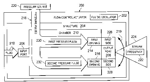
fluidic oscillator.
This type of flow control actuator is designed to produce a flow of fluid
moving in a sweeping
1
CA 2821970 2017-03-03
manner from side to side at an output port of the flow control actuator. These
oscillations of
fluid flow occur at a particular frequency. The fluid flow output by a fluidic
oscillator that moves
in a sweeping manner may be referred to as a sweeping jet.
[0006] Changing the frequency of the flow of fluids sweeping from side to side
to control fluid
flow in a particular system may be desirable in some cases. This frequency may
be changed to
provide a desired fluid flow for a particular aircraft structure by changing
the flow rate of fluid into
the fluidic oscillators. Currently, the frequency of the flow of fluid out of
a fluidic oscillator may
be changed by replacing the fluidic oscillator with another fluidic
oscillator. Replacement may
be undesirable when dynamic control of fluid flow by the fluid flow system is
desired.
[0007] Further, the frequency of oscillations in fluidic oscillators may be
changed during
operation of the fluidic oscillator by altering the supply pressure of the
fluid to the fluid oscillator.
However, in some cases, changing the fluid flow through the fluidic oscillator
may not be
desirable. For example, changing the fluid flow may use more energy than
desired in the
source of the fluid flow for the fluidic oscillator. In other cases, increased
maintenance may be
needed for the fluid source supplying fluid to the fluidic oscillator.
Therefore, it would be
desirable to have a method and apparatus that takes into account at least some
of the issues
discussed above, as well as possibly other issues.
SUMMARY
[0008] In one embodiment there is provided an apparatus that includes a
structure that
includes an input port directly connected to an opening through a first planar
member, a single
output port, and a chamber within the structure, such that the chamber
includes an indentation
in the first planar member that aligns with an indentation in a second planar
member, the first
planar member connected to the second planar member such that the connection
forms the
chamber and the chamber includes a first section directly connected to a
second section at a
rectangular shaped portion of the second section, such that the first section
includes a width
less than a diameter of the opening through the first planar member such that
the width
reduces, along a direction of flow of a fluid from the opening through the
first planar member to
the second section, until the first section connects to the second section.
The chamber further
includes a first side of the second section and a second side of the second
section configured to
diverge, along a direction of flow of the fluid from the rectangular shaped
portion of the second
2
CA 2821970 2017-03-03
section to the single output port, from each other and an axis that extends
centrally through the
chamber, until the first side and second side become substantially parallel to
each other before
turning substantially 180 degrees away from each other, and then return
substantially parallel to
each other before converging, along the direction of flow of the fluid from
the rectangular
shaped portion of the second section to the single output port, toward each
other, and the axis
that extends centrally through the chamber, until the first side and second
side directly connect
to the single output port, such that the chamber is configured to channel the
fluid from the input
port to the single output port of the structure, such that the opening through
the first planar
member connects to the first section and includes a central axis of the
opening through a depth
of the first planar member and substantially perpendicular to the axis that
extends centrally
through the chamber. The chamber further includes a first opening in the
rectangular shaped
portion of the second section and a second opening in the rectangular shaped
portion of the
second section, such that the first opening and the second opening are
configured to receive
pressure pulses through a first actuator and a second actuator respectively,
such that each
actuator extends from the first planar member with a respective central axis
of each actuator
being substantially parallel to the central axis of the opening through the
first planar member,
and each actuator configured to inject an energy level into the flow of the
fluid from the
rectangular shaped portion of the second section to the single output port,
such that the energy
level that each actuator injects remains less than 5% of an energy level of
the fluid flow as it
exits the single output port, such that a pressure magnitude of a pulse, of
the pressure pulses,
injected by each actuator, multiplied by a duration of the pulse injected by
each actuator
determines the energy level injected into the flow of the fluid from the
rectangular shaped
portion of the second section to the single output port.
[0009] The apparatus may include a pressure source in communication with the
first opening
and the second opening, and the pressure source may be configured to generate
the pressure
pulses.
[0010] The pressure source may be at least one source selected from a group of
sources
consisting of a pressurized fluid source, an acoustic system, a laser system,
and a spark
generation unit.
3
F04.40,4.1
CA 2821970 2017-03-03
[0011] The first opening and the second opening may be located to cause a
change in a
direction of the flow of the fluid out of the single output port in response
to receiving the
pressure pulses at the respective first and second openings.
[0012] The first opening and the second opening may be located to cause a
sweeping motion
of the fluid between a first side of the single output port and a second side
of the single output
port in response to receiving alternating pressure pulses at the respective
first and second
openings.
[0013] The first opening may be located on a first side of the single output
port and the second
opening may be located on a second side of the single output port and a first
pressure pulse in
the pressure pulses applied to the first opening causes the flow of the fluid
when the flow of the
fluid is occurring on the first side of the single output port to change
direction to the second side
of the single output port and a second pressure pulse in the pressure pulses
applied to the
second opening causes the flow of the fluid when the flow of the fluid is
occurring on the second
side of the single output port to change direction to the first side of the
single output port.
[0013a] The first opening may be located on the first side of the second
section and the second
opening may be located on the second side of the second section and the fluid
may move
between the first side and the second side of the second section in response
to the pressure
pulses being applied to the first opening and the second opening causing the
fluid flow to sweep
between a first side of the single output port and a second side of the single
output port.
[0013b] The first opening may be located opposite to the second opening about
an axis
extending centrally through the chamber.
[0013c] The first section may be configured to receive the fluid from the
input port and cause
the fluid to flow at a desired rate when exiting the first section and the
second section may be
configured to cause the fluid to move between the first side and the second
side in the second
section in response to the pressure pulses being applied to the first opening
and the second
opening. The second section may be in communication with the single output
port and the
single output port may be configured to cause the fluid flowing between the
first side and
second side in the second section to sweep with a frequency between a first
side of the single
output port and a second side of the single output port.
4
=
nY4 .
CA 2821970 2017-03-03
[0013d] The first opening may be located on the first side of the second
section and the second
opening may be located on the second side of the second section.
[0013e] The first opening may be located opposite to the second opening about
the axis that
extends centrally though the chamber.
[0013f] The structure may be comprised of a material selected from a group
consisting of a
metal, a plastic, steel, aluminum, titanium, and polycarbonate.
[0013g] The fluid may be selected from a group consisting of air, a liquid
fuel, and a gas fuel.
[0013h] In another embodiment there is provided a fluid flow control system
including a plurality
of flow control actuators. Each of the plurality of flow control actuators
includes a structure that
includes an input port directly connected to an opening through a first planar
member, a single
output port, and a chamber within the structure. The first planar member is
connected to a
second planar member such that the connection forms the chamber and the
chamber includes a
first section directly connected to a second section at a rectangular shaped
portion of the
second section, such that the first section comprises a width less than a
diameter of the opening
through the first planar member such that the width reduces, along a direction
of flow of a fluid
from the opening through the first planar member to the second section, until
the first section
connects to the second section. The chamber further includes a first side of
the second section
and a second side of the second section configured to diverge, along a
direction of flow of the
fluid from the rectangular shaped portion of the second section to the single
output port, from
each other and an axis that extends centrally through the chamber, until the
first side and
second side become substantially parallel to each other before turning
substantially 180
degrees away from each other and then return substantially parallel to each
other before
converging, along the direction of flow of the fluid from the rectangular
shaped portion of the
second section to the single output port, toward each other and the axis that
extends centrally
through the chamber until the first side and second side directly connect to
the single output
port, such that the chamber is configured to channel the fluid from the input
port to the single
output port of the structure, such that the opening through the first planar
member connects to
the first section and comprises a central axis of the opening through a depth
of the first planar
member and substantially perpendicular to the axis that extends centrally
through the chamber.
The chamber further includes a first opening in the rectangular shaped portion
of the second
. a.6====
WNW.
CA 2821970 2017-03-03
section, a second opening in the rectangular shaped portion of the second
section, and a
pressure source connected to a first actuator and a second actuator, each
actuator configured
to send pressure pulses to the first opening and the second opening
respectively, such that
each actuator extends from the first planar member with a respective central
axis of each
actuator being substantially parallel to the central axis of the opening
through the first planar
member.
[0013i] The pressure source may be configured to send the pressure pulses to
one of the first
opening and the second opening in each of the plurality of flow control
actuators in a manner
that controls the direction of flow of the fluid from the each of the
plurality of flow control
actuators.
[0013j] The fluid may be selected from a group consisting of air, a liquid
fuel, and a gas fuel.
[0013k] In another embodiment there is provided a method for managing a flow
of a fluid in an
apparatus including a first planar member connected to a second planar member
such that the
connection forms a chamber. The chamber includes an opening through a depth of
the first
planar member and a first section directly connected to a rectangular shaped
portion of a
second section, such that the first section comprises a width less than a
diameter of the opening
through the first planar member such that the width reduces, along a direction
of a flow of the
fluid from the opening through the first planar member to the second section,
until the first
section connects to the second section. The chamber further includes a first
side of the second
section and a second side of the second section configured to diverge, along a
direction of flow
of the fluid from the rectangular shaped portion of the second section to a
single output port,
from each other and an axis that extends centrally through the chamber, until
the first side and
second side become substantially parallel to each other before turning
substantially 180
degrees away from each other, and then return substantially parallel to each
other before
converging, along the direction of flow of the fluid from the rectangular
shaped portion of the
second section to the single output port, toward each other and the axis that
extends centrally
through the chamber until the first side and second side directly connect to
the single output
port, such that the chamber is configured to channel the fluid from an input
port to the single
output port such that the input port connects to the chamber via the opening
through the depth
of the first planar member, a central axis of the opening being substantially
perpendicular to the
axis that extends centrally through the chamber. The method involves a)
receiving the fluid at
5a
the input port, b) sending the fluid through the chamber in communication with
the opening
directly in communication with the input port, and c) causing the fluid to
flow from the chamber
and out of the single output port in a direction that changes with a frequency
based on applying
pressure pulses in the chamber via a second opening located in the rectangular
shaped portion
of the second section and connected to an actuator that extends from the first
planar member,
a central axis of the actuator is substantially parallel to the central axis
of the opening through
the first planar member, such that an energy level of a pulse of the pressure
pulses remains
less than 5% of an energy level of the fluid as it flows out the single output
port, such that the
energy level of the pulse equals a magnitude of the pulse multiplied by a
duration of the
pressure pulse.
[00131] The second section of the chamber may include an additional opening
and the method
may further involve applying the pressure pulses to the additional opening.
[0013m] The method may involve applying the pressure pulses to the opening and
the
additional opening in the chamber in an alternating manner that causes a
corresponding
alternating direction of the fluid flow out of the single output port.
[0013n] Applying the pressure pulses may involve applying alternating pressure
pulses to cause
a sweeping motion of the fluid between a first side of the single output port
and a second side of
the single output port.
[00130] The opening may be located on the first side of the second section and
the additional
opening may be located on the second side of the second section and the method
may involve
applying the pressure pulses to the opening and the additional opening to
cause the fluid to
move between the first side and the second side of the second section, causing
the fluid flowing
between the first side and the second side in the second section to sweep with
the frequency
between a first side of the single output port and a second side of the single
output port.
[0013p] The first section may receive the fluid from the input port and may
cause the fluid to
flow at a desired rate when exiting the first section and the second section
may communicate
with the first section and may cause the fluid to move between the first side
and the second side
in the second section in response to the pressure pulses being applied to an
additional opening
and the second opening. The second section may be in communication with the
single output
5b
CA 2821470 2017-07-26
CA 2821970 2017-03-03
port and the single output port may be configured to cause the fluid flowing
between the first
side and the second side in the second section to sweep with the frequency
between a first side
of the single output port and a second side of the single output port.
[0013q] The structure may comprise a material selected from one of a metal, a
plastic, steel,
aluminum, titanium, and polycarbonate. The fluid may be selected from one of
air, a liquid fuel,
and a gas fuel.
[0013r] In accordance with another disclosed aspect a fluid flow control
system may include a
plurality of flow control actuators, wherein each of the plurality of flow
control actuators includes
a structure having an input port and an output port; a chamber within the
structure, wherein the
chamber is configured to channel a fluid from the input port to the output
port of the structure; a
first opening in the chamber; a second opening in the chamber; and a pressure
source
configured to send pressure pulses to one of the first opening and the second
opening in the
each of the plurality of flow control actuators. The pressure source may be
configured to send
the pressure pulses to one of the first opening and the second opening in the
each of the
plurality of flow control actuators in a manner that controls a direction of a
flow of the fluid from
the each of the plurality of flow control actuators. The fluid may be selected
from one of air, a
liquid fuel, and a gas fuel.
[0014] The features and functions can be achieved independently in various
embodiments of
the present disclosure or may be combined in yet other embodiments in which
further details
can be seen with reference to the following description and drawings.
BRIEF DESCRIPTION OF THE DRAWINGS
[0015] The novel features believed characteristic of the illustrative
embodiments are set forth in
the appended claims. The illustrative embodiments, however, as well as a
preferred mode of
use, further objectives and features thereof, will best be understood by
reference to the
following detailed description of an illustrative
5c
CA 02821470 2013-07-18
embodiment of the present disclosure when read in conjunction with the
accompanying drawings, wherein:
[0016]Figure 1 is an illustration of an aircraft in accordance with an
illustrative
embodiment;
[0017]Figure 2 is an illustration of a block diagram of a flow control
actuator in
accordance with an illustrative embodiment;
[0018]Figure 3 is an illustration of a fluid flow control system in accordance
with an
illustrative embodiment;
[0019]Figure 4 is an illustration of a flow control actuator in accordance
with an
illustrative embodiment;
[0020]Figure 5 is an exploded view of a flow control actuator in accordance
with an
illustrative embodiment;
[0021]Figure 6 is another illustration of an exploded view of a flow control
actuator
in accordance with an illustrative embodiment;
(0022] Figure 7 is an illustration of a cross-sectional view of a flow control
actuator in
accordance with an illustrative embodiment;
[0023]Figure 8 is an illustration of an inner side of a first planar member in
a flow
control actuator in accordance with an illustrative embodiment;
(0024] Figures 9-11 are illustrations of oscillations of fluid flow for a flow
control
actuator in accordance with an illustrative embodiment;
[0025]Figure 12 is an illustration of a flow control actuator in accordance
with an
illustrative embodiment;
[0026]Figure 13 is an illustration of a view of inner sides of planar members
in a
flow control actuator in accordance with an illustrative embodiment;
[0027]Figure 14 is an illustration of a flowchart of a process for managing
flow of
fluid in accordance with an illustrative embodiment;
[0028]Figure 15 is an illustration of timing diagrams for a flow control
actuator in
accordance with an illustrative embodiment;
6
CA 02821470 2013-07-18
[0029] Figure 16 is an illustration of an aircraft manufacturing and service
method in
accordance with an illustrative embodiment; and
[0030]Figure 17 is an illustration of an aircraft in which an illustrative
embodiment
may be implemented.
DETAILED DESCRIPTION
[0031]The illustrative embodiments recognize and take into account one or more
different considerations. For example, the illustrative embodiments recognize
and
take into account that changing the pressure in the input of the fluidic
oscillator may
only change the frequency by an amount that may not be sufficient for the
desired
frequency range.
[0032]Additionally, the illustrative embodiments also recognize and take into
account
that changing the pressure of the fluid supplied to the fluidic oscillator may
also
change the velocity, momentum, or both the velocity and the momentum of the
fluid
that flows out of the fluidic oscillator. This type of change in output also
may be
undesirable in some cases. Further, changing the pressure from a fluid source
such
as a bleed air supply or an auxiliary power unit to provide desired frequency
in the
fluidic oscillator may require the use of more energy than desired.
[0033]Thus, the illustrative embodiments provide a method and apparatus for
controlling the fluid output from an apparatus such as a fluidic oscillator.
The
illustrative embodiments may be applied to any apparatus that generates fluid
flow at
an output port that changes frequency in the movement of the fluid flow that
sweeps
between a first side and a second side at the output port.
[0034] In one illustrative embodiment, an apparatus comprises a structure and
a
chamber. The structure has an input port and an output port. The chamber is
located within the structure and is configured to channel a fluid from the
input port to
the output port of the structure. Additionally, a first opening and a second
opening
are present in the chamber. The first opening and the second opening are
configured to receive pressure pulses.
7
CA 02821470 2013-07-18
[0035] In these illustrative examples, the frequency of the flow of fluid may
be the
rate, manner, or both the rate and manner of the fluid flow in a particular
direction.
This direction may be in a sweeping fashion from side to side. More
specifically, the
fluid may flow out of the output port in a stream that may move from side to
side at a
particular frequency. In other words when the flow of fluid sweeps at the
output port,
the flow of fluid moves from side to side. The side to side movement may not
actually touch the sides of the output port, depending on the implementation.
[0036] In these illustrative examples, the frequency in the change in
direction of the
flow of fluid out of the output port may be controlled using the pressure
pulses
received at the first opening and the second opening in the chamber. These
pressure pulses may be applied to the first opening and the second opening in
a
manner that controls the direction of the flow of fluid flowing out of the
output port.
[0037]With reference now to the figures and, in particular, with reference to
Figure
1, an illustration of an aircraft is depicted in accordance with an
illustrative
embodiment. In this illustrative example, aircraft 100 has wing 102 and wing
104
attached to body 106. Aircraft 100 includes engine 108 attached to wing 102
and
engine 110 attached to wing 104.
[0038] Body 106 has tail section 112. Horizontal stabilizer 114, horizontal
stabilizer
116, and vertical stabilizer 118 are attached to tail section 112 of body 106.
[0039]Aircraft 100 is an example of an aircraft in which flow control
actuators may be
implemented to control the flow of fluid for aircraft 100. In particular, flow
control
actuators in the form of fluidic oscillators may be implemented in aircraft
100 to
perform various functions such as maintaining a desired airflow. For example,
fluid
oscillators may be used to maintain desired airflow such as a boundary layer
over
wing 102, wing 104, horizontal stabilizer 114, horizontal stabilizer 116, and
vertical
stabilizer 118.
[0040] Further, fluid oscillators also may be employed to control surfaces
such as
flap 120 and flap 122. As another illustrative example, fluid oscillators may
be used
with engine 108 and engine 110 as well as other structures to reduce noise
generated by aircraft 100.
[0041]Turning now to Figure 2, an illustration of a block diagram of a flow
control
actuator is depicted in accordance with an illustrative embodiment. In this
illustrative
8
CA 02821470 2013-07-18
example, flow control actuator 200 may be used in aircraft 100 in Figure 1. In
this
illustrative example, flow control actuator is an externally driven flow
control actuator.
[0042]As depicted, flow control actuator 200 may take the form of fluidic
oscillator
202. In this illustrative example, flow control actuator 200 is comprised of
structure
204 having input port 206 and output port 208. Additionally, chamber 210 is
located
within structure 204. In this illustrative example, chamber 210 is an enclosed
space
in structure 204. Structure 204 may be comprised of a material selected from
one of
a metal, plastic, steel, aluminum, titanium, polycarbonate, or other suitable
types of
materials.
[0043]As depicted, chamber 210 is configured to channel fluid 212 from input
port
206 to output port 208 of structure 204. Fluid 212 may be, for example,
without
limitation, air, nitrogen, carbon dioxide, a liquid fuel, a gas fuel, or some
other
suitable type of fluid.
[0044] In this illustrative example, first opening 214 is present in chamber
210.
Additionally, second opening 216 also is present in chamber 210. First opening
214
and second opening 216 are configured to receive pressure pulses 218. Pressure
pulses 218 may originate from pressure source 220. Pressure source 220 may
take
various forms. For example, pressure source 220 may be selected from at least
one
of a pressurized fluid source, an acoustic system, a laser system, a spark
generation
unit, and some other suitable source.
[0045]As used herein, the phrase "at least one of," when used with a list of
items,
means different combinations of one or more of the listed items may be used
and
only one of each item in the list may be needed. For example, "at least one of
item
A, item B, and item C" may include, without limitation, item A or item A and
item B.
This example also may include item A, item B, and item C, or item B and item
C. In
other examples, "at least one of' may be, for example, without limitation, two
of item
A, one of item B, and ten of item C; four of item B and seven of item C; and
other
suitable combinations.
[0046] In these illustrative examples, pressure source 220 is configured to
generate
pressure pulses 218 and send pressure pulses 218 to at least one of first
opening
214 and second opening 216 in chamber 210. The application of pressure pulses
218 to one of first opening 214 and second opening 216 results in pressure
pulses
9
CA 02821470 2013-07-18
218 being applied within chamber 210. The application of pressure pulses 218
to
one of first opening 214 and second opening 216 is configured to change
frequency
222 at which fluid 212 changes direction when flowing out of output port 208.
[0047] In this illustrative example, fluid 212 flows in the form of stream
224. Stream
224 sweeps with frequency 222. In these illustrative examples, stream 224
moves in
a sweeping motion from side to side as depicted by arrow 219. In these
illustrative
examples, stream 224 may take the form of a jet stream of air.
[0048] In these illustrative examples, the change in the direction of flow of
fluid 212
out of output port 208 is a sweeping motion between first side 226 of output
port 208
and second side 228 of output port 208. In this illustrative example, first
opening 214
is located on first side 226 of output port 208. Second opening 216 is located
on
second side 228 of output port 208. In these illustrative examples, first
pressure
pulse 230 in pressure pulses 218 is configured to cause a flow of fluid 212
occurring
on first side 226 of output port 208 to change direction to second side 228 of
output
port 208. Second pressure pulse 232 applied to second opening 216 is
configured
to cause the flow of fluid 212 occurring on second side 228 of output port 208
to
change direction to first side 226 of output port 208.
[0049]The illustration of flow control actuator 200 in Figure 2 is not meant
to imply
physical or architectural limitations to the manner in which an illustrative
embodiment
may be implemented. Other components in addition to or in place of the ones
illustrated may be used. Some components may be unnecessary. Also, the blocks
are presented to illustrate some functional components. One or more of these
blocks may be combined, divided, or combined and divided into different blocks
when implemented in an illustrative embodiment.
[00501In Figure 3, an illustration of a fluid flow control system is depicted
in
accordance with an illustrative embodiment. In this depicted example, fluid
flow
control system 300 may be used to control flow 302 of fluid 303 over surface
304 of
object 306. Object 306 may be, for example, aircraft 100 in Figure 1, or some
part
of aircraft 100 in Figure 1. In other illustrative examples, object 306 may be
a
ground vehicle, an engine inlet, or some other suitable object.
[0051] In this illustrative example, fluid flow control system 300 is
comprised of flow
control actuators 308. One or more of flow control actuators 308 may be
CA 02821470 2013-07-18
implemented using flow control actuator 200 in Figure 2. As depicted, flow
control
actuators 308 may generate flows 310 of fluid 312 that are introduced into
flow 302
of fluid 303. Flows 310 of fluid 312 may be used to manage the manner in which
flow 302 of fluid 303 flows over surface 304 of object 306.
[0052] In these illustrative examples, flows 310 of fluid 312 may change
direction
from side to side as indicated by arrow 314 out of flow control actuators 308.
This
change in direction may be in a sweeping motion. In these illustrative
examples,
fluid 312 may be the same fluid as fluid 303 or may be a different fluid
depending on
the particular implementation.
[0053] In these illustrative examples, pressure pulse system 316 sends
pressure
pulses 318 to flow control actuators 308. Pressure pulse system 316 may be
comprised of a group of pressure pulse sources. As used herein, a "group of"
when
used with reference to items means one or more items. For example, a group of
pressure pulse sources is one or more group of pressure pulses.
[0054]The application of these pressure pulses to flow control actuators 308
control
the change in direction of flows 310 of fluid 312. The application of pressure
pulses
318 to flow control actuators 308 may be such that the frequency in the
movement of
flows 310 of fluid 312 are synchronized. In other words, the sweeping motion
of
flows 310 of fluid 312 may all move in the same manner. In other illustrative
examples, different flows within flows 310 may have different frequencies and
may
point in different directions from other flows within flows 310.
[0055]The phase and the frequency of the pressure pulses to flow control
actuators
308 may be selected in response to the phase and frequency of the pressure
fluctuations in flow 302 such that the desired characteristics are present in
flow 302.
In this illustrative example, the frequency input, phase input, or both of the
inputs to
pressure pulse system 316 that control pressure pulses 318 may be obtained
from
flow 302 in a location upstream of where flow 302 is modified by flows 310.
[0056]Turning now to Figure 4, an illustration of a flow control actuator is
depicted in
accordance with an illustrative embodiment. Flow control actuator 400 is an
example of one physical implementation of flow control actuator 200 shown in
block
form in Figure 2. As depicted, flow control actuator 400 may be fluidic
oscillator 402.
11
CA 02821470 2013-07-18
[0057] In this illustrative example, flow control actuator 400 is comprised of
structure
404 having input port 406 and output port 407. Structure 404 is an example of
an
implementation of structure 204 shown in block form in Figure 2. Input port
406 and
output port 407 are examples of physical implementations for input port 206
and
output port 208 shown in block form in Figure 2.
[0058]As depicted in this particular example, structure 404 is comprised of
more
than one part. In particular, structure 404 is comprised of first planar
member 408
and second planar member 410. These planar members may be connected to each
other through fastener 412, fastener 414, fastener 416, fastener 418, fastener
419,
and fastener 420.
[0059] In this illustrative example, pressure source 422 is associated with
first planar
member 408. Pressure source 422 is an example of an implementation for
pressure
source 220 in Figure 2. As depicted, pressure source 422 includes first
actuator 428
and second actuator 430. As depicted, first actuator 428 and second actuator
430
are associated with first planar member 408. First actuator 428 and second
actuator
430 control the application of pressure pulses to a chamber (not shown) within
the
interior of structure 404.
[0060] Line 431 is connected to both first actuator 428 and second actuator
430.
First actuator 428 controls a fluid under pressure within line 431. When first
actuator
428 is activated, fluid within line 431 may flow through first actuator 428
into the
chamber in structure 404. Similarly, when second actuator 430 is active, fluid
may
flow through second actuator 430 into the chamber in structure 404.
[0061]in this illustrative example, input port 406 extends from surface 424 of
first
planar member 408. Input port 406 is configured to be connected to a fluid
source.
For example, input port 406 may be connected to a bleed air source or an
auxiliary
power unit in these depicted examples.
[0062]As depicted, output port 407 is located on first planar member 408 on
inner
side 432 of structure 404. In this illustrative example, fluid flows out of
output port
407 in a direction that moves with a selected frequency. The frequency may be
selected by controlling pressure pulses applied to the chamber in structure
404
through first actuator 428 and second actuator 430.
12
CA 02821470 2013-07-18
[0063]Turning now to Figure 5, an exploded view of a flow control actuator is
depicted in accordance with an illustrative embodiment. In this exploded view
of flow
control actuator 400, inner side 500 of second planar member 410 is shown.
Inner
side 500 may contact inner side 432 of first planar member 408 when first
planar
member 408 and second planar member 410 are connected to each other.
[0064] In this view, first opening 506 and second opening 510 are present in
first
planar member 408. First actuator 428 may be in communication with first
opening
506 and second actuator 430 may be in communication with second opening 510
when in an assembled form.
[0065]As depicted, input port 406 is comprised of connector 520 and opening
522.
Connector 520 may be placed into opening 522 to form input port 406.
[0066]Turning now to Figure 6, another illustration of an exploded view of a
flow
control actuator is depicted in accordance with an illustrative embodiment. In
this
exploded view of flow control actuator 400, chamber 600 is seen on inner side
432 of
first planar member 408. Chamber 600 has volume 602 in this illustrative
example.
[0067]As depicted, chamber 600 is in communication with first opening 506 and
second opening 510. These openings are entry points for pressure pulses that
may
be generated by pressure source 422.
[0068]With reference now to Figure 7, an illustration of a cross-sectional
view of a
flow control actuator is depicted in accordance with an illustrative
embodiment. As
depicted, flow control actuator 400 is shown in a cross-sectional view taken
along
lines 7-7 in Figure 4.
[0069] In this view, valve 700 is shown within interior 702 of first actuator
428. Valve
704 is shown within interior 706 of second actuator 430.
[0070]As depicted, valve 700 in first actuator 428 provides communication
between
line 431 and first opening 506. When valve 700 is open, fluid may flow through
line
431 through valve 700 into first opening 506. By selectively opening and
closing
valve 700, pressure pulses may be sent through first opening 506.
[0071] In this illustrative example, valve 704 in second actuator 430 provides
communication between line 431 and second opening 510. When valve 704 is open,
fluid may flow through line 431 through valve 704 into second opening 510. By
13
CA 02821470 2015-07-28
selectively opening and closing valve 704, pressure pulses may be sent through
second
opening 510.
[0072] Other components within first actuator 428 and second actuator 430 are
not shown in
this cross-sectional view. These components are omitted to avoid obscuring the
illustration of
features in the illustrative embodiment relating to generating pressure
pulses.
[0073] With reference now to Figure 8, an illustration of an inner side of a
first planar member
in a flow control actuator is depicted in accordance with an illustrative
embodiment. In this
figure, inner side 432 of first planar member 408 from Figure 4 is
illustrated.
[0074] As can be seen in this illustrative example, first planar member 408
has chamber 600.
Chamber 600 includes first section 800 and second section 802. First section
800 of chamber
600 is in communication with opening 522 of input port 406 in Figure 4 at
first end 804 of first
section 800. First section 800 may be configured to receive fluid 813 from
input port 406 and
may cause fluid 813 to flow at a desired rate.
Second end 806 of first section 800 is in
communication with first end 808 of second section 802 of chamber 600 through
section 812. In
this illustrative example, second end 810 of second section 802 is in
communication with output
port 407.
[0075] As used herein, a first component, first end 804 of first section 800,
"connected to" a
second component, second section 802, means that the first component can be
connected
directly or indirectly to the second component. In other words, additional
components may be
present between the first component and the second component. The first
component is
considered to be indirectly connected to the second component when one or more
additional
components are present between the two components. When the first component is
directly
connected to the second component, no additional components are present
between the two
components.
[0076] Further, fluid 813 may flow out of output port 407 in a stream about
axis 814 extending
centrally through chamber 600. This stream may have various forms, such as a
jet, a cone, a
fan shape, or some other suitable form.
14
CA 02821470 2013-07-18
[0077]As can be seen in this illustrative example, when fluid 813 flows out of
flow
control actuator 400 at output port 407, fluid 813 may spread out to cover
area 822.
As depicted, area 822 represents an extent of flow for fluid 813.
[0078] The extent of area 822 outside of flow control actuator 400 may depend
on
the configuration of output port 407. Output port 407 may be made such that
area
822 may be wider or narrower, or have other configurations depending on the
particular implementation.
[0079] In this illustrative example, pressure pulses may be applied to at
least one of
first opening 506 and second opening 510 in chamber 600 and are configured to
cause fluid 813 to oscillate between first side 824 of second section 802 and
second
side 826 of second section 802. In other words, pressure pulses may be applied
to
first opening 506 and second opening 510 in an alternating manner to cause
fluid
813 to oscillate between first side 824 and second side 826 of second section
802.
This oscillation between first side 824 and second side 826 is configured to
cause an
oscillation of fluid 813 as it exits flow control actuator 400 at output port
407. The
oscillation of fluid 813 may be between first side 816 and second side 818 of
output
port 407 in Figure 4.
[0080] In the illustrative examples, the oscillation of fluid 813 may occur
using energy
levels of less than about 5 percent of the energy in fluid 813 as an input to
generating the pressure pulses through first opening 506 and second opening
510
as it exits flow control actuator 400 at output port 407. The energy level may
be
expressed as pressure magnitude multiplied by pulse duration. The selection of
the
energy level may be made to reduce the use of external energy needed to cause
fluid 813 to oscillate.
[0081] In this manner, the application of pressure pulses into second section
802 of
chamber 600 through first opening 506 and second opening 510 may cause fluid
813
to oscillate within second section 802, which in turn causes oscillation of
fluid 813
when fluid 813 flows out of output port 407. At least one of the frequency and
phase
of this oscillation may be adjusted by adjusting the manner in which pressure
pulses
are applied through first opening 506 and second opening 510 in second section
802
of chamber 600.
CA 02821470 2015-07-28
[0082] Turning now to Figures 9-11, illustrations of oscillations of fluid
flow for a flow control
actuator are depicted in accordance with an illustrative embodiment. In Figure
9, an illustration
of fluid flow out of a flow control actuator is shown. In this illustration,
fluid 813 flows through
second section 802 such that fluid is present on first side 824 with an
absence of fluid 813 on a
portion of second side 826 in second section 802 of chamber 600. This flow of
fluid 813 results
in fluid 813 flowing out of output port 407 toward second side 826 with a flow
of fluid 813 in area
900 on first side 824 being substantially absent.
[0083] In this figure, a pressure pulse has been previously applied to second
opening 510. In
this illustration, the application of the pressure pulse to second opening 510
results in the flow of
fluid 813 in area 822 to be in a direction that is towards second side 818 of
output port 407.
[0084] In Figure 10, an illustration of a flow of fluid out of a flow control
actuator is depicted in
accordance with an illustrative embodiment. In this example, a pressure pulse
has been applied
to second opening 510 in second section 802 of chamber 600.
[0085] Within chamber 600, fluid 813 sweeps or moves to flow out of output
port 407 from
second side 826 toward first side 824 in response to the pressure pulse
applied to first opening
506. Fluid 813 flowing within second section 802 of chamber 600 flows mainly
about axis 814
as the flow of fluid 813 shifts from flowing on first side 824 to second side
826. Flow of fluid 813
is substantially absent in area 1000 in second section 802 of chamber 600 in
this example.
[0086] As depicted, fluid 813 flows out of output port 407 in a direction
substantially along axis
814. In this illustration, the flow of fluid 813 has moved toward second side
818 and is moving
away from first side 816 of output port 407 in response to the pressure pulse
applied to first
opening 506.
[0087] Turning now to Figure 11, an illustration of a flow of fluid out of a
flow control actuator is
depicted in accordance with an illustrative embodiment. In this depicted
example, fluid 813
flows through second section 802 of chamber 600 with fluid 813 being mostly
against second
side 826 rather than first side 824. Fluid flow is substantially absent from
area 1100 on first side
824 of second section 802 of chamber 600 in these illustrative examples. This
type of flow
through second section
16
CA 02821470 2013-07-18
802 results in the flow of fluid 813 in area 822 to be in a direction that is
towards first
side 816 of output port 407.
[0088]The flow of fluid 813 remains on first side 816 of output port 407 until
a
pressure pulse is applied to second opening 510. An application of the
pressure
pulse to second opening 510 will cause the flow of fluid 813 to sweep back
towards
second side 818.
[0089] In this manner, an application of pressure pulses to first opening 506
and
second opening 510 may be made to cause fluid 813 to move from side to side.
In
these illustrative examples, fluid 813 moves from one side to another side in
response to the pressure pulse through one of first opening 506 and second
opening
510.
[0090]The application of pressure pulses to first opening 506 and second
opening
510 may be applied in a manner that results in a movement in the direction at
which
fluid 813 flows with a desired frequency. In these illustrative examples, the
frequency alternating between pressure pulses applied to first opening 506 and
second opening 510 correspond to the frequency at which fluid 813 oscillates
or
sweeps between first side 816 and second side 818 of output port 407.
[0091] Turning now to Figure 12, an illustration of a flow control actuator is
depicted
in accordance with an illustrative embodiment. In this depicted example, flow
control
actuator 1200 takes the form of fluidic oscillator 1202. Flow control actuator
1200 is
an example of another physical implementation for flow control actuator 200
shown
in block form in Figure 2.
[0092] In this illustrative example, structure 1204 is comprised of first
planar member
1206 and second planar member 1208. Structure 1204 has input port 1214 and
output port 1216.
[0093] In this illustrative example, input port 1214 extends from surface 1218
of first
planar member 1206. In this illustrative example, output port 1216 is not
located just
in first planar member 1206. Output port 1216 is located in both first planar
member
1206 and second planar member 1208 in this illustrative example. Additionally,
first
actuator 1220 and second actuator 1222 are associated with a first opening
(not
shown) in first planar member 1206 and a second opening (not shown) in first
planar
17
CA 02821470 2013-07-18
member 1206. First actuator 1220 and second actuator 1222 are connected to
line
1224.
[0094]Turning now to Figure 13, an illustration of a view of inner sides of
planar
members in a flow control actuator is depicted in accordance with an
illustrative
embodiment. In this example, inner side 1300 for first planar member 1206 and
inner side 1302 for second planar member 1208 are shown. In this illustrative
example, chamber 1304 is formed in both inner side 1300 of first planar member
1206 and inner side 1302 of second planar member 1208.
[0095]Additionally, first opening 1306 and second opening 1308 are located on
inner
side 1300 of first planar member 1206.
[0096]The different components shown in Figure 1 and Figures 4-13 may be
combined with components in Figure 2 and 3, used with components in Figures 2
and 3, or a combination of the two. Additionally, some of the components in
Figure
1 and Figures 4-13 may be illustrative examples of how components shown in
block
form in Figures 2 and 3 can be implemented as physical structures.
[0097]With reference now to Figure 14, an illustration of a flowchart of a
process for
managing flow of fluid is depicted in accordance with an illustrative
embodiment.
The process illustrated in Figure 14 may be implemented in flow control
actuator
200 in Figure 2. In particular, the process may be implemented using flow
control
actuator 200 in aircraft 100 in Figure 1 or some other suitable type of
platform.
[0098]The process begins by receiving fluid at an input port of a structure
(operation
1400). The process then sends the fluid through a chamber in communication
with
the input port (operation 1402). The process then causes the fluid to flow
from the
chamber and out of an output port in a direction that changes with a frequency
based
on an application of pressure pulses in the chamber (operation 1404). In these
illustrative examples, the pressure pulses are applied to different sides of
the
chamber through a first opening and a second opening in the chamber. Each time
a
pressure pulse is applied to one of the sides, the flow of fluid out of the
output port
may move to another side of the output port.
[0099]A determination is made as to whether a change in the frequency of the
flow
of the fluid from the output port to another frequency is needed (operation
1406). If a
change is not needed, the process returns to operation 1400. Otherwise, the
18
CA 02821470 2013-07-18
process changes the manner in which the pressure pulses are applied to the
chamber while the fluid flows through the chamber to change the flow of fluid
with
the frequency from the output port to another frequency (operation 1408), with
the
process then returning to operation 1400. These operations may occur until
fluid
flow is no longer desired from the structure.
[00100] The flowcharts and block diagrams in the different depicted
embodiments illustrate the architecture, functionality, and operation of some
possible
implementations of apparatus and methods in an illustrative embodiment. In
this
regard, each block in the flowcharts or block diagrams may represent a module,
segment, function, and/or a portion of an operation or step.
[00101] In some alternative implementations of an illustrative embodiment,
the
function or functions noted in the blocks may occur out of the order noted in
the
figures. For example, in some cases, two blocks shown in succession may be
executed substantially concurrently, or the blocks may sometimes be performed
in
the reverse order, depending upon the functionality involved. Also, other
blocks may
be added in addition to the illustrated blocks in a flowchart or block
diagram.
[00102] Turning now to Figure 15, an illustration of timing diagrams for a
flow
control actuator is depicted in accordance with an illustrative embodiment.
Timing
diagrams 1500 are examples of timing diagrams that may be generated for flow
control actuator 200 in Figure 2. Timing diagram 1502 illustrates oscillations
in the
flow of fluid at output port 208 in Figure 2. X-axis 1504 represents time,
while Y-axis
1506 represents a side at which fluid flow occurs at output port 208.
[00103] Timing diagram 1508 illustrates pressure pulses 218 applied to
first
opening 214 in chamber 210 in Figure 2. X-axis 1510 represents time, while
time Y-
axis 1512 represents a magnitude of a pressure pulse applied to first opening
214.
[00104] Next, timing diagram 1514 illustrates pressure pulses 218 applied
to
second opening 216 in chamber 210 in Figure 2. X-axis 1516 represents time,
while
time Y-axis 1518 represents a magnitude of a pressure pulse applied to second
opening 216.
[00105] In these illustrative examples, the pressure pulse has a duration
that is
selected to cause the flow of fluid to change direction from one side of
output port
208 to the other side of output port 208. For example, the pressure pulse may
have
19
CA 02821470 2013-07-18
a duration of about 0.25 milliseconds to about 25 milliseconds. The magnitude
of the
pressure pulse may be selected to be proportional to the total pressure of the
fluid
flowing in the cavity, stagnation pressure of the fluid flowing in the cavity,
or in some
other suitable manner.
[00106] As can be seen in this illustrative example, a pressure pulse is
applied
at time TO to first opening 214. As can be seen, the flow of fluid in timing
diagram
1502 is on second side 228 of output port 208. At time T1, a pressure pulse is
applied to second opening 216. This pressure pulse causes the flow of fluid to
move
back to first side 226 of output port 208. At time T3 a pressure pulse is
applied to
first opening 214. This causes the flow of fluid to move back to second side
228 of
output port 208. At time T4, a pressure pulse is applied to second opening
216.
This pressure pulse causes the flow of fluid to move back to first side 226 of
output
port 208.
[00107] At time T5, a pressure pulse is applied at first opening 214. This
pressure pulse causes the flow of fluid to move from first side 226 to second
side
228 of output port 208. At time T6, a pressure pulse is applied at second
opening
216. As a result, the fluid flow at output port 208 returns to the first side
226 of
output port 208. At time T7, a pressure pulse is applied to first opening 214.
This
pressure pulse causes the flow of fluid to move back from first side 226 to
second
side 228 at output port 208.
[00108] As can be seen, the frequency between the alternating pressure
pulses
to first opening 214 and second opening 216 has increased at time T6. As a
result,
the movement of the flow of fluid between first side 226 and second side 228
also
increases in frequency. In other words, the amount of time between movement of
the flow of fluid between first side 226 and second side 228 of output port
208
increases.
[00109] Also, when a pressure pulse is not applied to either first opening
214 or
second opening 216, the flow of fluid at output port 208 does not move between
first
side 226 and second side 228 of output port 208.
[00110] Illustrative embodiments of the disclosure may be described in the
context of aircraft manufacturing and service method 1600 as shown in Figure
16
and aircraft 1700 as shown in Figure 17. Turning first to Figure 16, an
illustration of
CA 02821470 2013-07-18
an aircraft manufacturing and service method is depicted in accordance with an
illustrative embodiment. Flow control actuator 200 and the components found in
flow
control actuator 200 may be manufactured or reconfigured in the steps shown in
this
figure. During pre-production, aircraft manufacturing and service method 1600
may
include specification and design 1602 of aircraft 1700 in Figure 17 and
material
procurement 1604.
[00111] During production, component and subassembly manufacturing 1606
and system integration 1608 of aircraft 1700 in Figure 17 takes place.
Thereafter,
aircraft 1700 in Figure 17 may go through certification and delivery 1610 in
order to
be placed in service 1612. While in service 1612 by a customer, aircraft 1700
in
Figure 17 is scheduled for routine maintenance and service 1614, which may
include modification, reconfiguration, refurbishment, and other maintenance or
service.
[00112] Each of the processes of aircraft manufacturing and service method
1600 may be performed or carried out by a system integrator, a third party,
and/or an
operator. In these examples, the operator may be a customer. For the purposes
of
this description, a system integrator may include, without limitation, any
number of
aircraft manufacturers and major-system subcontractors; a third party may
include,
without limitation, any number of vendors, subcontractors, and suppliers; and
an
operator may be an airline, a leasing company, a military entity, a service
organization, and so on.
[00113] With reference now to Figure 17, an illustration of an aircraft is
depicted in which an illustrative embodiment may be implemented. In this
example,
aircraft 1700 is produced by aircraft manufacturing and service method 1600 in
Figure 16 and may include airframe 1702 with plurality of systems 1704 and
interior
1706. Examples of systems 1704 include one or more of propulsion system 1708,
electrical system 1710, hydraulic system 1712, and environmental system 1714.
Any number of other systems may be included. Although an aerospace example is
shown, different illustrative embodiments may be applied to other industries,
such as
the automotive industry.
[00114] Apparatuses and methods embodied herein may be employed during
at least one of the stages of aircraft manufacturing and service method 1600
in
21
CA 02821470 2013-07-18
Figure 16. For example, flow control actuators may be designed for use in
aircraft
1700 during specification and design 1602. The flow control actuators may be
manufactured during component and subassembly manufacturing 1606 and installed
during system integration 1608. In these illustrative examples, the flow
control
actuators may be tested during certification and delivery 1610 and used to
control
the flow of fluids while in service 1612. Additionally, flow control actuators
may be
added or replaced during maintenance, upgrades, or refurbishment in
maintenance
and service 1614.
[00115] Thus, the illustrative embodiments provide a method and apparatus
for
controlling the flow of a fluid out of a flow control actuator. In the
illustrative
embodiments, the frequency at which fluid changes directions when flowing out
of an
output port in a flow control actuator may be changed. This frequency or
sweeping
of the fluid flow may be changed in a manner that does not require a change in
the
pressure of fluid input into the flow control actuator at an input port.
[00116] In the illustrative examples, the change in the direction of fluid
flow is
caused by the application of pressure pulses to the chamber in which the fluid
flows.
In these illustrative examples, the pressure pulses are applied to a first
opening and
a second opening in the chamber in an alternating manner that causes the fluid
to
flow out of the output port with a desired frequency. In this manner, the
amount of
fuel or energy needed to operate a fluid source may be reduced. Further, by
maintaining the flow of fluid at substantially the same level, changes in
fluid flow may
not occur that may affect the control being initiated using a fluid flow
actuator.
[00117] The description of the different illustrative embodiments has been
presented for purposes of illustration and description, and is not intended to
be
exhaustive or limited to the embodiments in the form disclosed. Many
modifications
and variations will be apparent to those of ordinary skill in the art.
[00118] Although the illustrative examples for an illustrative embodiment
are
described with respect to an aircraft, an illustrative embodiment may be
applied to
other types of platforms. The plafform may be, for example, a mobile plafform,
a
stationary platform, a land-based structure, an aquatic-based structure, and a
space-
based structure. More specifically, the platform may be a surface ship, a
tank, a
personnel carrier, a train, a spacecraft, a space station, a satellite, a
submarine, an
22
CA 02821470 2013-07-18
automobile, a power plant, a bridge, a dam, a manufacturing facility, a
building, and
other suitable objects.
[00119] Further,
different illustrative embodiments may provide different
features as compared to other illustrative embodiments. The embodiment or
embodiments selected are chosen and described in order to best explain the
principles of the embodiments, the practical application, and to enable others
of
ordinary skill in the art to understand the disclosure for various embodiments
with
various modifications as are suited to the particular use contemplated.
23