Note: Descriptions are shown in the official language in which they were submitted.
CA 02821476 2013-07-12
Description
Title of the Invention: INKJET RECORDING APPARATUS
Technical Field
[0001]
The present invention relates to an inkjet recording apparatus, and in
particular
to an inkjet recording apparatus of a pressure control type can make a
distribution tank
compact and has excellent pressure-control precision.
Background Art
[0002]
Inkjet recording apparatuses are used in various fields since they can perform
high-speed successive recording of designs or characters based on
predetermined image
data.
Examples of such inkjet recording apparatuses include a known inkjet recording
apparatus provided with a back-pressure tank, a distribution tank, an ink on-
off solenoid
valve, and a recording head (for example, see Patent Literature 1 or 2).
[0003]
By the way, in these inkjet recording apparatuses, since ink is supplied by
making use of a water head difference between the liquid level in the back-
pressure tank
and the recording head, there is a certain limitation in a positional relation
between the
back-pressure tank and the recording head.
In addition, since a route through which ink passes from the back-pressure
tank
to the recording head is long, there is such a drawback that pressure loss
occurs.
Further, since the pressure on ink in the recording head varies according to
the
liquid level in the back-pressure tank, there is the drawback that the
discharge amount or
discharge velocity of the ink becomes unstable.
[0004]
1
CA 02821476 2013-07-12
In order to overcome these drawbacks, an inkjet recording apparatus of a
pressure control type that controls pressure instead of making use of a water
head
difference has been developed.
For example, there is an inkjet recording apparatus provided with a main tank,
a
sub tank, a print head (recording head), a pressure detecting means for
detecting a
pressure in the sub tank, an air suction means, and an air replenishment pump
(for
example, see Patent Literature 3).
Citation List
Patent Literature
PTL 1: Japanese Patent Application Laid-Open No. 2012-11668
PTL 2: Japanese Patent Application Laid-Open No. 2012-11669
PTL 3: Japanese Patent No. 4734938
Summary of invention
Technical Problem
[0006]
However, in the above inkjet recording apparatus described in Patent
Literature
3, since the volume of the sub tank is small, pressure control becomes
difficult, so that it
cannot be said that the precision is excellent.
In addition, since the pressure detecting means, the air suction means, and
the
air replenishment pump need to be attached to the sub tank, the structure of
the apparatus
becomes complicated, and the weight of the sub tank also increases. Therefore,
the sub
tack cannot be moved efficiently.
Further, since the sub tank itself becomes large, there is also the drawback
that
an extra space for installation is required.
[0007]
The present invention has been made in view of the above circumstances, and an
object of the present invention is to provide an inkjet recording apparatus
which can
make a distribution tank (sub tank) compact and has excellent pressure-control
precision.
2
CA 02821476 2013-07-12
Solution to Problems
[0008]
The present inventors have made intensive research to solve the above problems
and have completed the present invention based on the finding that the above
problems
can be solved by disposing at a separate location an air chamber communicating
with a
space in a distribution tank and attaching a pressure adjusting mechanism to
the air
chamber.
[0009]
The present invention lies in (1) an inkjet recording apparatus including: an
inkjet portion having a recording head for applying ink to a recording medium
and a
distribution tank for supplying ink to the recording head; an ink supply means
having a
main tank for supplying ink to the distribution tank; and an air supply means
having an
air chamber communicating with a space in the distribution tank and a pressure
adjustment mechanism provided on the air chamber via a solenoid valve, wherein
pressure of the space and internal pressure of the air chamber are equal to
each other.
[0010]
The present invention lies in (2) the inkjet recording apparatus according to
the
above (1), wherein the internal volume of the air chamber is larger than the
volume of
the space.
[0011]
The present invention lies in (3) the inkjet recording apparatus according to
the
above (1), wherein the volume ratio of a volume R1 of the space to an internal
volume
R2 of the air chamber (R1:R2) is in a range of 1:1.28 to 1:73.3.
[0012]
The present invention lies in (4) the inkjet recording apparatus according to
any
one of the above (1) to (3), wherein: the ink supply means and the air supply
means are
contained in a fluid portion; and the inkjet portion and the fluid portion are
separate
members.
[0013]
3
CA 02821476 2013-07-12
The present invention lies in (5) the inkjet recording apparatus according to
any
one of the above (1) to (4), wherein the distribution tank supplies the ink to
the recording
head via an ink on-off solenoid valve.
[0014]
The present invention lies in (6) the inkjet recording apparatus according to
any
one of the above (1) to (5), wherein the main tank supplies ink to the
distribution tank via
a deaerating module.
[0015]
The present invention lies in (7) the inkjet recording apparatus according to
any
one of the above (1) to (6), wherein the distribution tank is provided with a
circulation
port; and ink in the distribution tank is circulated from the circulation port
to the main
tank through a circulating flow passage connected to the circulation port.
[0016]
The present invention lies in (8) the inkjet recording apparatus according to
any
one of the above (1) to (7), wherein: the recording head includes a plurality
of recording
head sections; the distribution tank includes a plurality of distribution tank
sections
corresponding to the number of the recording head sections; and spaced in the
distribution tank sections communicate with the air chamber which is one in
number.
[0017]
The present invention lies in (9) the inkjet recording apparatus according to
any
one of the above (1) to (8), wherein the pressure adjustment mechanism
includes: a
vacuum pump attached to the air chamber via a pressure-reducing solenoid
valve; an air
filter attached to the air chamber via an ambient-air solenoid valve so as to
communicate
with ambient air; and a pressurizing pump attached to the air chamber via a
pressurizing
solenoid valve.
[0018]
The present invention lies in (10) a method for controlling the inkjet
recording
apparatus according to any one of the above (1) to (9), including the steps
of: performing
control to make the pressure in the air chamber negative during inkjet
recording and
during storage of the recording head; and performing control to make the
pressure in the
4
CA 02821476 2013-07-12
air chamber positive during restoring work where the ink is forcibly
discharged from the
recording head.
[0019]
The present invention lies in (11) a method for controlling the inkjet
recording
apparatus according to the above (9), including the steps of: performing
control to make
the pressure in the air chamber negative during inkjet recording and during
storage of the
recording head; performing control to make the pressure in the air chamber
positive
during restoring work where the ink is forcibly discharged from the recording
head; and
shifting the pressure in the air chamber to atmospheric pressure via the air
filter
temporarily in the course of changing from the negative pressure to the
positive pressure
or changing from the positive pressure to the negative pressure.
Advantageous Effects of Invention
[0020]
In the inkjet recording apparatus of the present invention, since the pressure
in
the air chamber is equal to the pressure of the space in the distribution
tank, by adjusting
the pressure in the air chamber, the pressure of the space in the distribution
tank can be
similarly adjusted. Therefore, for example, according to the specifications of
the inkjet
recording apparatus, the air chamber can be installed at an arbitrary
location.
At this time, if the internal volume of the air chamber is larger than the
volume
of the space, the pressure in the distribution tank can be controlled with
higher precision.
That is, since controlling the pressure in the distribution tank is performed
through
controlling the pressure in the air chamber, for example, a sudden change in
pressure
never occurs directly in the distribution tank.
[0021]
In the inkjet recording apparatus of the present invention, since the air
chamber
is disposed at a separate location, the pressure adjustment mechanism can be
attached to
the air chamber. Therefore, the distribution tank to which the pressure
adjustment
mechanism is not directly attached can be made more compact. This provides the
merit
that a large space to install the distribution tank is not required, and,
since the weight of
CA 02821476 2013-07-12
the distribution tank can also be reduced, the inkjet portion including the
distribution
tank can be moved very efficiently.
[0022]
Incidentally, since the inkjet recording apparatus of the present invention is
of a
pressure control type, a positional relation between the main tank and the
recording head
is not limited, so that a route through which ink flows from the main tank to
the
recording head can be shortened in order to reduce pressure loss, and the ink
discharge
amount or discharge velocity can be stabilized. As a result, high-speed and
high-
coverage inkjet recording becomes possible.
[0023]
In the inkjet recording apparatus of the present invention, when the ink
supply
means and the air supply means are contained in the fluid portion, and the
inkjet portion
and the fluid portion are separate member, the inkjet portion can be made more
compact,
and the fluid portion can be disposed at an unobstructive desired location.
Thereby, the
working capacity of the inkjet recording can also be improved.
[0024]
In the inkjet recording apparatus of the present invention, when the
distribution
tank is configured to supply ink to the recording head via an ink on-off
solenoid valve,
ink can be forcibly supplied to the recording head. Thereby, clogging of the
recording
head or the like can be prevented or eliminated.
[0025]
In the inkjet recording apparatus of the present invention, when the main tank
is
configured to supply ink to the distribution tank via a deaerating module,
generation of
air bubbles in the ink can be suppressed. As a result, an ink discharge defect
in the
recording head can be suppressed.
At this time, when the distribution tank is provided with a circulation port,
and
the ink in the distribution tank is circulated from the circulation port to
the main tank via
a circulating flow passage connected to the circulation port, the ink can be
repeatedly
deaerated, so that an ink discharge defect can be further suppressed in the
recording head.
[0026]
6
CA 02821476 2013-07-12
In the inkjet recording apparatus of the present invention, when a plurality
of
recording head sections are provided, a plurality of distribution tank
sections are
provided so as to correspond to the number of the recording head sections, and
spaces in
these distribution tank sections communicate with one air chamber, the
pressures of the
spaces in these distribution tank sections are adjusted at the same time as
adjustment of
the pressure in the one air chamber, so that the pressures in the individual
distribution
tank sections can be averaged.
[0027]
In the inkjet recording apparatus of the present invention, when the pressure
adjustment mechanism includes a vacuum pump attached to the air chamber via a
pressure-reducing solenoid valve, an air filter attached to the air chamber
via an ambient-
air solenoid valve so as to communicate with ambient air, and a pressurizing
pump
attached to the air chamber via a pressurizing solenoid valve, the pressure
can be easily
adjusted.
In addition, since the air filter communicating with ambient air is used, dust
can
be prevented from entering the air chamber.
[0028]
In the method for controlling the inkjet recording apparatus of the present
invention, by controlling the pressure in the air chamber so as to become
negative at the
time of inkjet recording and at the time of storing the recording head, ink
leakage can be
suppressed, and by controlling the pressure in the air chamber to become
positive, ink is
forcibly discharged from the recording head, so that a discharge defect can be
eliminated.
[0029]
It should be noted that it is preferred that the pressure in the air chamber
be
temporarily shifted to atmospheric pressure via the air filter in the course
of changing
from the negative pressure to the positive pressure or changing from the
positive pressure
to the negative pressure.
Brief Description of Drawings
[0030]
7
CA 02821476 2013-07-12
Figure 1 is a descriptive diagram showing schematically a relationship between
inkjet portions, air supply means, and an ink supply means in an inkjet
recording
apparatus according to an embodiment of the present invention;
Figure 2 is a descriptive diagram showing schematically a relationship between
the inkjet portion and the ink supply means in the inkjet recording apparatus
according to
the embodiment;
Figure 3 is a descriptive diagram showing schematically a relationship between
the inkjet portions and the air supply means in the inkjet recording apparatus
according
to the embodiment;
Figure 4 is a front view showing the inkjet portion in the inkjet recording
apparatus according to the embodiment;
Figure 5a is a right side view of a fluid portion in the inkjet recording
apparatus
according to the embodiment;
Figure 5b is a left side view of a fluid portion in the inkjet recording
apparatus
according to the embodiment; and
Figures 6a and 6b are descriptive diagrams showing schematically relationships
between inkjet portions, air supply means, and an ink supply means in inkjet
recording
apparatuses according to other embodiments.
Description of Embodiments
[0031]
Hereinafter, with reference to Figures, if necessary, preferred embodiments of
the present invention will be described in detail. It should be noted that in
Figures
identical elements are denoted by identical reference signs so that the same
description is
not repeated. In addition, positional relationships, such as top and bottom or
right and
left, are based on positional relationships in Figures, unless otherwise
noted. Further,
dimensional ratios of the drawings and ratios of illustrations are not limited
to those
shown in Figures.
[0032]
8
CA 02821476 2013-07-12
Figure 1 is a descriptive diagram showing schematically a relationship between
inkjet portions, air supply means, and an ink supply means in an inkjet
recording
apparatus according to an embodiment of the present invention. As shown in
Figure 1,
the inkjet recording apparatus according to the present invention is provided
with four
inkjet portions A, four ink supply means B for supplying ink to the inkjet
portions A,
respectively, and one air supply means C for supplying air to these inkjet
portions A.
It should be noted that more specifically the inkjet portion A has a recording
head for applying ink to a recording medium and a distribution tank for
supplying ink to
the recording head, the ink supply means B has a main tank for supplying ink
to the
distribution tank, and the air supply means C has an air chamber
conununicating with a
space in the distribution tank and a pressure adjusting mechanism provided on
the air
chamber via a solenoid valve.
[0033]
Since the inkjet recording apparatus according to the embodiment is of a
pressure control type, there are no limitations on a positional relationship
between the
main tank and the recording head. Therefore, a route through which ink flows
from the
main tank to the recording head can be shortened in order to reduce pressure
loss, and
consequently the discharge amount or discharge velocity of the ink can be
stabilized.
As a result, a high-speed and high-coverage inkjet recording becomes possible.
[0034]
In the inkjet recording apparatus according to the embodiment, the inkjet
portions A are supplied with inks different in color by the ink supply means
B,
respectively.
For example, full-color inkjet recording is made possible by causing the
inkjet
portions A to contain yellow (Y), magenta (M), cyan (C), and black (K) inks,
respectively.
[0035]
Further, these inkjet portions A communicate with the one air supply means C.
That is, the inkjet portions A have a plurality of recording heads, and a
plurality of
9
CA 02821476 2013-07-12
distribution tanks corresponding to the number of the recording heads, and
spaces in
these distribution tanks communicate with the one air chamber.
Therefore, by controlling the pressure in the air chamber in the air supply
means
C, the pressures of the spaces in the distribution tanks in these inkjet
portions A are
adjusted, so that the pressures in the distribution tanks in the individual
inkjet portions A
can be averaged.
[0036]
Figure 2 is a descriptive diagram showing schematically a relationship between
the inkjet portion and the ink supply means in the inkjet recording apparatus
according to
the embodiment.
As shown in Figure 2, the inkjet portion A has a recording head 11 for
applying
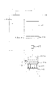
ink to a recording medium (not shown) and a distribution tank 12 for supplying
the
recording head 11 with ink.
[0037]
A fixed line head having a plurality of nozzles is used as the recording head
11.
Further, as described above, since the inkjet portions A have a plurality of
recording heads 11, different inks can be used in the respective recording
heads 11.
[0038]
The distribution tank 12 contains ink, and a space 12a is provided in the rest
of
the distribution tank 12. Incidentally, the fluid level of the ink within the
distribution
tank 12 is monitored by a float switch, and the ink is controlled so as to
keep the amount
within an appropriate range.
In addition, the distribution tank 12 has a built-in warming heater so that
the ink
is controlled so as to keep the temperature constant.
Further, a plurality of ink on-off solenoid valves 12b are directly attached
to a
lower end of the distribution tank 12, and the ink on-off solenoid valves 12b
are
connected to the corresponding recording head 11 via distribution supply pipes
12c
attached to the ink on-off solenoid valves 12b, respectively.
[0039]
CA 02821476 2013-07-12
The distribution tank 12 is configured to discharge ink from the recording
head
11 according to opening and closing of the ink on-off solenoid valve 12b,
based on a
signal from a controller (not shown), after the pressure in the air chamber
has been made
positive.
When the ink on-off solenoid valve 12b is opened, the ink is forcibly supplied
to
the recording head 11 and discharged from the nozzles of the recording head
11.
Therefore, clogging of the recording head 11 or the like can be prevented or
eliminated.
[0040]
The ink supply means B has a main tank 21 from which ink is supplied to the
distribution tank 12 via a deaerating module 22 and an ink pack 23 from which
ink is
supplied to the main tank 21. Incidentally, the main tank 21 is opened to the
atmosphere via an air filter (not shown).
Further, a check valve 25 for preventing backflow of ink is attached between
the
deaerating module 22 and the distribution tank 12.
[0041]
In the ink supply means B, ink is supplied from the main tank 21 to the
distribution tank 12 via the deaerating module 22 based on a signal from the
float switch.
Therefore, generation of air bubbles in the ink can be suppressed, and
consequently an
ink discharge defect in the recording head 11 can be suppressed. Incidentally,
the ink is
supplied by a pump (not shown).
[0042]
In the inkjet recording apparatus according to the embodiment, a circulation
port
13 is provided in a lower portion of the distribution tank 12 so that the ink
in the
distribution tank 12 is circulated through the circulation port 13 to the main
tank 21 via a
circulating flow passage 13a joined to the circulation port 13. Incidentally,
the ink is
circulated by a pump (not shown).
Since the ink is unidirectionally circulated between the distribution tank 12
and
the main tank 21 in this manner, the ink can be deaerated repeatedly.
Therefore, an ink
discharge defect in the recording head can be further prevented. Incidentally,
it is
11
CA 02821476 2013-07-12
preferred that such circulation be performed not only during inkjet recording
but also
during no-recording.
[0043]
Figure 3 is a descriptive diagram showing schematically a relationship between
the inkjet portions and the air supply means in the inkjet recording apparatus
according
to the embodiment.
As shown in Figure 3, the air supply means C has an air chamber 31
communicating with the spaces 12a in the distribution tanks 12 and a pressure
adjustment
mechanism provided on the air chamber 31 via a solenoid valve.
[0044]
In the inkjet recording apparatus according to the embodiment, the pressure in
the air chamber 31 is equal to the pressures of the spaces 12a in the
distribution tanks 12,
so that in conjunction with adjustment of the pressure in the air chamber 31,
the
pressures of the spaces 12a in the distribution tanks 12 is similarly
adjusted.
In addition, since the air chamber 31 provided with the pressure adjustment
mechanism is provided separately from the distribution tanks 12, it is
unnecessary to
attach the pressure adjustment mechanism to the distribution tank 12, unlike a
conventional manner, so that the distribution tank 12 can be made compact.
Further, since the air chamber 31 is a member separate from the distribution
tanks 12, the air chamber 31 can be installed anywhere in conformity to
specifications of
inkjet recording apparatuses.
Furthermore, even if backflow of ink occurs, the ink can be trapped in the air
chamber 31, so that an accident can be avoided.
[0045]
In this regard, the internal volume of the air chamber 31 is larger than the
volume of the space 12a.
Since pressure fluctuation in the air chamber 31 due to the pressure
adjustment
mechanism becomes smaller as the volume of the air chamber 31 increases, the
pressure
in the distribution tank can be controlled with higher precision by adjusting
the pressure
12
CA 02821476 2013-07-12
in the air chamber 31 having the larger volume than by adjusting the pressure
of the
space 12a directly like a conventional manner.
Further, when the ink is consumed, the internal pressure of the sealed
distribution tank 12 varies toward negative pressure, but, since the air
chamber 31 is
connected to the space 12a of the distribution tank 12 so that the volume of
the air
chamber 31 increases, the degree of pressure variation based on the
consumption of ink
can be made smaller.
[0046]
In this regard, a volume ratio (R1 :R2) of a volume R1 of the space to an
internal
volume R2 of the air chamber is preferably in a range of 1:1.28 to 1:73.3,
more
preferably in a range of 1:1.28 to 1:36.7.
If the internal volume R2 of the air chamber 31 is less than 1.28 times the
volume R1 of the space 12a, the effect that pressure control can be performed
with
higher precision might not be obtained, as compared with the case where the
internal
volume R2 of the air chamber 31 is within the above range, and if the internal
volume R2
of the air chamber 31 is more than 73.3 times the volume R1 of the space 12a,
the air
chamber 31 becomes excessively large, and an extra space might be required, as
compared with the case where the internal volume R2 of the air chamber 31 is
within the
above range.
[0047]
The pressure adjustment mechanism includes a vacuum tank 33 attached to the
air chamber 31 via a pressure-reducing solenoid valve 32a, a vacuum pump 35a
connected to the vacuum tank 33, an air filter 35b attached to the air chamber
31 via an
ambient-air solenoid valve 32b so as to communicate with ambient air, and a
pressurizing pump 35c attached to the air chamber 31 via a pressurizing
solenoid valve
32c.
Further, pressure gauges 39 for monitoring pressure are attached to the air
chamber 31 and the vacuum tank 33, respectively.
[0048]
13
CA 02821476 2013-07-12
In this regard, it is preferred that a reciprocating vacuum pump or an ejector
type
vacuum pump be used as the vacuum pump 35a in view of durability, and it is
preferred
that a reciprocating compressor be used as the pressurizing pump 35c in view
of
durability.
Further, the vacuum pump 35a is set so as to have a pressure of -5 to -6 kPa,
for
example, and the pressurizing pump 35c is set so as to have a pressure of
approximately
98 kPa.
[0049]
The vacuum pump 35a is attached via the vacuum tank 33. Therefore, even if
air suddenly inflows, a breakdown of the vacuum pump 35a is suppressed due to
existence of the vacuum tank 33.
[0050]
The pressure in the air chamber 31 is made negative by the vacuum pump 35a
based on opening and closing of the pressure-reducing solenoid valve 32a, is
made equal
to atmospheric pressure based on opening and closing of the ambient-air
solenoid valve
32b, and is made positive by the pressurizing pump 35c based on opening and
closing of
the pressurizing solenoid valve 32c.
Since the pressure adjustment mechanism attached to the air chamber 31 uses
these solenoid valves in this manner, the precision of pressure control is
excellent.
Here, the "negative pressure" means a pressure reduced to lower than
atmospheric pressure, while the "positive pressure" means a pressure increased
to higher
than atmospheric pressure.
[0051]
In the inkjet recording apparatus according to the present invention, since
the
pressure adjustment mechanism is provided with the vacuum pump 35a, the air
filter 35b,
and the pressurizing pump 35c, the pressure can be easily adjusted. The
details of the
control will be described later.
[0052]
The inkjet recording apparatus according to the present invention is provided
with a fluid portion containing the ink supply means B and the air supply
means C, and
14
CA 02821476 2013-07-12
includes the inkjet portion A and the fluid portion containing the ink supply
means B and
the air chamber means C.
[0053]
In this regard, in the inkjet recording apparatus, the inkjet portion A is a
member
separate from the fluid portion. Therefore, it becomes possible to make the
inkjet
portion A compact and dispose the fluid portion at an unobstructive desired
location.
Thereby, the working capacity of the inkjet recording can also be improved.
Further, for example, if the fluid portion is disposed so as to have the main
tank
21 near the inkjet portion A, pressure loss due to a piping route can be
reduced, so that it
becomes possible to reduce the size of an ink supply pump and enhance the life
thereof.
[0054]
The inkjet portion A, as described above, has the recording head 11 for
applying
ink to a recording medium and the distribution tank 12 for supplying ink to
the recording
head 11.
In addition to these components, of course, the inkjet portion A may have a
common inkjet configuration.
[0055]
Figure 4 is a front view showing the inkjet portion in the inkjet recording
apparatus according to the embodiment.
As shown in Figure 4, in addition to the recording head 11 for applying ink to
a
recording medium 1 and the distribution tank (not shown) for supplying ink to
the
recording head 11, the inkjet portion A may have guide rollers 2 guiding the
recording
medium traveling, a drying machine 3 for drying the recording medium 1 which
has been
subjected to recording by the recording head 11, and a main body frame 5
containing
these members.
[0056]
Here, examples of the recording medium 1 include, but not limited to, a paper,
a
film, a cloth, a metallic foil, or another suitable material.
CA 02821476 2013-07-12
Further, the drying machine 3 has a cylindrical dryer, where the recording
medium 1 is dried by bringing the recording medium 1 which has been applied
with
inkjet recording in close contact with a surface of the dryer.
[0057]
In the inkjet recording portion A, the recording medium which has been fed
therein is guided by the guide rollers 2 to the recording head 11. Then, the
recording
head 11 performs inkjet recording on the recording medium 1.
The recording medium 1 which has been subjected to inkjet recording is guided
by other guide rollers 2 to the drying machine 3, and dried therein.
Thereafter, the dried
recording medium 1 is guided by other guide rollers 2 and discharged to the
outside.
[0058]
The fluid portion, as described above, contains the ink supply means B and the
air supply means C.
Figure 5a is a right side view of the fluid portion in the inkjet recording
apparatus according to the embodiment as viewed from the right side, and
Figure 5b is a
left side view of the fluid portion in the inkjet recording apparatus
according to the
embodiment as viewed from the lift side.
As shown in Figures 5a and 5b, the fluid portion has wheels and can move
freely.
[0059]
In the right side of the fluid portion, as shown in Figure 5a, the fluid
portion has
the ink packs 23 placed on the top face thereof. In the inner rear side, the
main tanks 21
connected to their respective corresponding ink packs 23 via pumps by means of
tubes
and the deaerating modules 22 connected to the main tanks 21 via tubes are
disposed.
Incidentally, the deaerating modules 22 are connected to the distribution
tanks of the
inkjet portions A (not shown) via tubes. The check valves 25 are not shown in
Figure
5a.
[0060]
On the other hand, the vacuum tank 33 is disposed in an inner front side of
the
fluid portion. Incidentally, the vacuum pump 35a, the air filter 35b, and the
pressurizing pump 35c are not shown in Figure 5a.
16
CA 02821476 2013-07-12
[0061]
In the left side of the fluid portion, as shown in Figure 5b, the fluid
portion has
the ink packs 23 placed on the top face thereof. In the inner rear side, the
main tanks 21
connected to their respective corresponding ink packs 23 via pumps by means of
tubes
and the deaerating modules 22 connected to the main tanks 21 via tubes are
disposed.
Incidentally, the deaerating modules 22 are connected to the distribution
tanks of the
inkjet portions A (not shown) via tubes. The check valves 25 are not shown in
Figure
5b.
[0062]
On the other hand, the air chamber 31 is disposed in an inner front side of
the
fluid portion. Incidentally, the solenoid valves 32a, 32b, 32c are not shown
in Figure
5b.
The front, rear, right, and left of the fluid portion are not particularly
limited to
those in Figures 5a and 5b, and, of course, these directions can be reversed.
[0063]
In a control method of the inkjet recording apparatus according to the
embodiment, the pressure in the air chamber is controlled so as to be negative
during
inkjet recording and during storage of the recording head 11.
Further, during restoring work where ink is forcibly discharged from the
recording head 11, the pressure in the air chamber 31 is controlled so as to
be positive.
For these reasons, ink leakage during inkjet recording and during storage of
the
recording head 11 can be suppressed, and, since the pressure in the air
chamber 31 is
controlled so as to be positive during restoring work where ink is forcibly
discharged
from the recording head 11, clogging of ink in the recording head 11 can be
suppressed.
[0064]
In a control method of the inkjet recording apparatus according to the
embodiment, since the ambient-air solenoid valve 32b communicating with
atmospheric
pressure is attached to the air chamber 31, the loads on the pumps when the
pressure is
changed from positive to negative or when the pressure is changed from
negative to
positive can be reduced by opening the ambient-air solenoid valve 32b halfway
to
17
CA 02821476 2013-07-12
temporarily make the pressure equal to atmospheric pressure via the air filter
35b. That
is, the negative pressure in the air chamber 31 can be once shifted to the
atmospheric
pressure, and then to the positive pressure, or the positive pressure in the
air chamber 31
can be once shifted to the atmospheric pressure, and then to the negative
pressure.
[0065]
Though the embodiment of the present invention has been described above, the
present invention is not limited to the above embodiment.
[0066]
For example, the inkjet recording apparatus according to the above embodiment
is provided with four inkjet portions A, four ink supply means for supplying
ink to each
of the inkjet portions B, and one air supply means for supplying air to these
inkjet
portions C, but the number of inkjet portions A and the number of ink supply
means B
for supplying ink to the inkjet portions A are not particularly limited.
For example, the number of the inkjet portions A, the number of ink supply
means B, and the number of air supply members C may be the same as each other,
or
may be different from each other.
[0067]
Figures 6(a) and 6(b) are descriptive diagrams showing schematically relations
between inkjet portions, air supply means, and an ink supply means(s) in
inkjet recording
apparatuses according to other embodiments.
As shown in Figure 6(a), eight inkjet portions A, eight ink supply means B for
supplying inks to the inkjet portions A, respectively, and one air supply
means C for
supplying air to these inkjet portions A may be provided.
In addition, as shown in Figure 6(b), two sets of four inkjet portions A, four
ink
supply means B for supplying ink to each of the inkjet portions A, and one air
supply
means C for supplying air to these ink portions A may be provided.
Incidentally, if air
supply means C is provided at a plurality of places, a plurality of air
chambers may share
a common vacuum tank.
[0068]
18
CA 02821476 2013-07-12
In the inkjet recording apparatus according to the above embodiment, the
inkjet
portions A contain yellow (Y), magenta (M), cyan (C), and black (K) inks,
respectively,
but the inks are not limited to these YMCK.
For example, if five or more inkjet portions A are provided, a plurality of
inkjet
portions A may contain inks in the same color, or the inkjet portion A may
contain an ink
in neutral color, an ink in fluorescent color, an ink containing an anti-
weathering agent,
or the like.
[0069]
The inkjet recording apparatus according to the above embodiment is of a line
head system using a line head in the recording head 11, but the recording head
may be of
a serial head system.
[0070]
In the inkjet recording apparatus according to the above embodiment, the
pressure adjustment mechanism is provided with the air filter 35b attached to
the air
chamber 31 via the ambient-air solenoid valve 32b so as to communicate with
ambient
air, but the air filter 35b is not necessarily essential.
[0071]
In the inkjet recording apparatus according to the above embodiment, the
pressure-reducing solenoid valve 32a, the ambient-air solenoid valve 32b, and
the
pressurizing solenoid valve 32c are directly attached to the air chamber 31,
but these
solenoid valves may be attached via a manifold through which an air inflow
route to the
air chamber 31 is shared.
[0072]
In the inkjet recording apparatus according to the above embodiment, the
inkjet
portion A and the fluid portion are separate members, but may be integrated
with each
other. That is, for example, the fluid portion may be contained in the main
body frame
of the inkjet portion A shown in Figure 4.
[0073]
19
CA 02821476 2013-07-12
In the inkjet recording apparatus according to the above embodiment shown in
Figures 5a and 5b, the ink packs 23 are placed on the top face of the fluid
portion, but
may be contained therein.
The vacuum pump, the air filter, and the pressurizing pump may also be
installed outside the fluid portion.
Industrial Applicability
[0074]
The present invention can be used as an inkjet recording apparatus of a
pressure
control type using a recording head to perform recording on a recording
medium.
According to such an inkjet recording apparatus, the distribution tank can be
made
compact, and the precision of pressure control is excellent.
Reference Signs List
1.. .recording medium,
2...guide roller,
3...drying machine,
5...main body frame,
11.. .recording head,
12...distribution tank,
12a...space,
12b...ink on-off solenoid valve,
12c...distribution supply pipe,
13.. .circulation port,
13a...circulating flow passage,
21.. .main tank,
22...deaerating module,
23...ink pack,
25...check valve,
31.. .air chamber,
CA 02821476 2013-07-12
32a. .pressure-reducing solenoid valve,
32b...ambient-air solenoid valve,
32c...pressurizing solenoid valve,
33...vacuum tank,
35a...vacuum pump,
35b. .air filter,
35c...pressurizing pump,
39...pressure gauge,
A...inkjet portion,
B...ink supply means, and
C.. .air supply means.
21