Note: Descriptions are shown in the official language in which they were submitted.
CA 02821874 2013-06-14
WO 2012/089930
PCT/F12011/051174
1
A METHOD AND AN APPARATUS FOR PRODUCING NANOCELLULOSE
Field of the invention
This invention relates to a method for producing nanocellulose, wherein cel-
lulose based fibre raw material is processed mechanically to separate
microfibrils. The invention also relates to an apparatus for producing nano-
cellulose.
Background of the invention
Mechanical pulp is produced industrially by grinding or refining wood raw
material. In grinding, whole tree trunks are pressed against a rotating cylin-
drical surface, whose surface structure is formed to detach fibres from the
wood. The obtained pulp is discharged with spraywaters from the grinder to
fractionation, and the reject is refined in a disc refiner. This method
produces
pulp that contains short fibres and scatters light well. A typical example to
be
mentioned of a grinding process is US patent 4,381,217. In the manufacture
of refiner mechanical pulp, the starting material consists of wood chips which
are guided to the centre of a disc refiner, from where they are transferred by
the effect of a centrifugal force and a steam flow to the circumference of the
refiner while being disintegrated by the blades on the surface of the disc.
Typically, multi-phase refining is necessary for obtaining finished pulp in
this
process. The coarse fraction separated in the process can be directed into
so-called reject refining. This method produces pulp with longer fibres com-
pared to the above-described groundwood. Refining processes have been
presented in, for example, publications WO-9850623, US 4,421,595, and US
7,237,733.
By said methods, mechanical pulp is produced, in which the fibres of wood
raw material have been separated from each other and possibly refined fur-
ther, depending on the energy used. By these methods, pulp is obtained in
which the fibres fall within the dimensions of wood fibres, typically having a
diameter greater than 20 m. Fibre raw material with the same particle size
can be obtained by preparing chemical pulp, that is, by processing the wood
raw material chemically to separate the fibres. Cellulose containing fibre raw
CA 02821874 2013-06-14
WO 2012/089930
PCT/F12011/051174
2
material obtained by mechanical or chemical pulping is commonly used for
manufacturing paper or cardboard products.
Wood fibres can also be disintegrated into smaller parts by removing fibrils
which act as components in the fibre walls, wherein the particles obtained
become significantly smaller in size. The properties of so-called nanocellu-
lose thus obtained differ significantly from the properties of normal
cellulose.
By using nanocellulose, it is possible to provide a product with, for example,
better tensile strength, lower porosity and at least partial translucency,
corn-
pared with using cellulose. Nanocellulose also differs from cellulose in its
appearance, because nanocellulose is gel-like material in which the fibrils
are
present in a water dispersion. Because of the properties of nanocellulose, it
has become a desired raw material, and products containing it would have
several uses in industry, for example as an additive in various compositions.
Nanocellulose can be isolated as such directly from the fermentation process
of some bacteria (including Acetobacter xylinus). However, in view of large-
scale production of nanocellulose, the most promising potential raw material
is raw material of plant origin and containing cellulose fibres, particularly
wood. The production of nanocellulose from wood raw material requires the
decomposition of the fibres further to the size class of fibrils. In
processing, a
cellulose fibre suspension is run several times through a homogenizing step
that generates high shear forces in the material. For example in US patent
4,374,702, this is achieved by guiding the suspension under high pressure
repeatedly through a narrow opening where it achieves a high speed. In pat-
ents US 5,385,640; US 6,183,596; and US 7,381,294; in turn, refiner discs
are presented, between which a fibre suspension is fed several times.
In practice, the production of nanocellulose from cellulose fibres of the con-
ventional size class can, at present, only be implemented by disc refiners of
laboratory scale, which have been developed for the needs of food industry.
This technique requires several refining runs in succession, for example 5 to
10 runs, to obtain the size class of nanocellulose. The method is also poorly
scalable up to industrial scale.
CA 02821874 2013-06-14
WO 2012/089930
PCT/F12011/051174
3
Summary of the invention
It is an aim of the invention to present a method for preparing nanocellulose,
in which there may be fewer refining runs and which can be implemented
better also in a larger scale than the laboratory scale, for example in semi-
industrial or industrial scale. To attain this purpose, the method according
to
the invention is primarily characterized in that
¨ the mechanical processing is performed by introducing a mixture of cellu-
lose based fibre raw material and water at a low consistency of advanta-
geously 1.5 to 4.5% and preferably 2 to 4% through a ring-shaped refining
gap having a width smaller than 0.1 mm and formed between refining sur-
faces performing a relative movement in the direction of the periphery of the
ring, an inner refining surface and an outer refining surface, the diameter of
the gap increasing in the direction of feeding the mixture;
¨ in the refining gap, the fibre raw material is subjected to processing
forces
varying in the direction of introducing said mixture, by means of refining
zones provided one after each other in the feeding direction in the gap,
whereby the refining surfaces are different in their surface pattern and/or
surface roughness;
¨ the mixture of fibre raw material and water is guided past the refining sur-
faces to different points of the refining zone in the feeding direction; and
¨ the width of the refining gap is maintained by the combined effect of the
feeding pressure of the mixture of fibre raw material and water fed into the
refining gap and the axial force of the inner refining surface.
In practice, the above-described method can be implemented in an appara-
tus of the type of a conical refiner, in which the ring-like refining gap is
provided between the opposite refining surfaces expanding conically in the
feeding direction. The inner refining surface of the refining gap is the outer
surface of the rotating rotor expanding conically in the feeding direction,
and
its outer refining surface is the inner surface of the stator whose inner part
expands conically in the feeding direction. Thus, the diameter of the narrow
ring-like refining gap becomes wider in the direction of the rotating axis of
the
rotor.
With the conical shape,_a long refining area is achieved in the feeding direc-
tion, whose length is determined on the basis of the cone angle and which
CA 02821874 2013-06-14
WO 2012/089930
PCT/F12011/051174
4
can be divided in the feeding direction into successive zones in which the
fibres are subjected to different types of processing. Similarly, the
direction of
the centrifugal force generated by the movement of the inner refining surface
in the pulp is not the same as the direction of movement of the pulp between
the inlet end and the outlet end; that is, the centrifugal force also presses
the
pulp to be processed towards the outer refining surface instead of moving the
pulp in the longitudinal direction of the refining zone only. Advantageously,
the refining zones become finer in the feeding direction, with respect to the
surface pattern and/or roughness of the refining surface. In the feeding direc-
tion, there may initially be a blade patterning, and at the end, the
mechanical
effect on the fibre material is obtained by mere surface roughness. This can
be implemented by means of hard particles attached to the surface and being
similar to "grits" used in refining processes, which make up a uniform
refining
surface. Advantageously, the rough surface is formed on the refining surface
by spraying a suitably hard material. The surface roughness provides a
friction surface where the refining work is of "mangling" type.
As the mixture of cellulose based fibre raw material and water proceeds in
such a refining gap, fibrils which form nanocellulose are separated from the
fibres.
There may be two zones performing mangling work by means of surface
roughness, a mixing zone being provided in between.
The setting of the refining gap plays an important role in the invention,
because it has an effect on the refining result. The desired width of the
refin-
ing gap is obtained by the combined effect of the pressure of the mixture of
fibre raw material and water fed into the refining gap and the axial force of
the inner refining surface. A particularly good alternative to keeping the
refining gap constant is to apply a constant volume supply of the mixture into
the refiner so that the volumetric flow remains constant irrespective of the
feeding pressure. This can be achieved with fixed volume pumps of prior art,
whose output is independent of the pressure.
CA 02821874 2013-06-14
WO 2012/089930
PCT/F12011/051174
Brief description of the drawings
The invention will be described in the following with reference to the
appended drawings, in which:
5
Fig. 1 shows an apparatus according to the invention, in a vertical
cross-section in the direction of the rotation axis of the rotor;
Fig. 2 shows an example of successive refining zones of the rotor as a
top plan view; and
Fig. 3
illustrates the general principle of operation of the method
according to the invention.
Detailed description of the invention
In this application, nanocellulose refers to cellulose microfibrils or
microfibril
bundles separated from cellulose based fibre raw material. These microfibrils
are characterized by a high aspect ratio (length/diameter): their length may
exceed 1 pm, whereas the diameter typically remains smaller than 200 nm.
The smallest microfibrils are in the size class of so-called elementary
fibrils,
where the diameter is typically 2 to 12 nm. The dimensions and size distribu-
tion of nanocellulose particles depend on the refining method and efficiency.
Nanocellulose can be characterized as a cellulose based material, in which
the median length of particles (fibrils or fibril bundles) is not greater than
10 pm, for example between 0.2 and 10 pm, advantageously not greater than
1 pm, and the particle diameter is smaller than 1 pm, suitably ranging from
2 nm to 200 nm. Nanocellulose is characterized by a large specific surface
area and a strong ability to form hydrogen bonds. In water dispersion, nano-
cellulose typically appears as colourless, gel-like material. Depending on the
fibre raw material, nanocellulose may also contain some hemicellulose. Often
used parallel names for nanocellulose include nanofibrillated cellulose (NFC)
and microfibrillated cellulose (MFC).
In this application, the term "refining" generally refers to comminuting
material
mechanically by work applied to the particles, which work may be grinding,
crushing or shearing, or a combination of these, or another corresponding
action that reduces the particle size. The energy taken by the refining work
is --
CA 02821874 2013-06-14
WO 2012/089930
PCT/F12011/051174
6
normally expressed in terms of energy per processed raw material quantity,
in units of e.g. kWh/kg, MWh/ton, or units proportional to these.
The refining is performed at a low consistency of the mixture of fibre raw
material and water, the fibre suspension. Hereinbelow, the term pulp will also
be used for the mixture of fibre raw material and water subjected to refining.
The fibre raw material subjected to refining may refer to whole fibres, parts
separated from them, fibril bundles, or fibrils, and typically the pulp is a
mix-
ture of such elements, in which the ratios between the components are
dependent on the stage of refining.
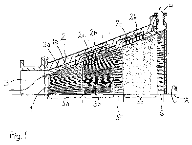
Figure 1 shows an apparatus in which the method according to the invention
can be applied. The apparatus is a refiner operating by the principle of a
conical refiner comprising a rotor 1 arranged to rotate with respect to a rota-
tion axis A, and a fixed stator 2 surrounding the rotor. As to the structure
of
the rotor and the stator, only the part above the axis A is shown, because the
structure is symmetrical with respect to the axis A. The rotor is rotated by
an
external power source, for example an electric motor (not shown). A ring-
shaped refining gap is formed between the rotor and the stator, into which
gap the fibre pulp to be processed is supplied at a suitable consistency from
the first end of the refiner via an inlet opening 3 in the stator. The inner
refin-
ing surface la of the refining gap consists of the outer surface of the rotor
1,
and its outer refining surface 2a consists of the inner surface of the stator.
The diameter of the ring-shaped refining gap increases in the direction of the
rotation axis A of the rotor, seen from the first end of the refiner, because
the
rotor and the stator expand conically in this direction. The overall feeding
direction of pulp supplied into the refiner coincides with the rotation axis A
of
the rotor, taking into account the fact that the pulp is carried in the
refining
gap through the refiner along a route in the shape of a conical mantle, whose
central axis is formed by said axis A. The material refined in the refining
gap
exits through the outlet opening 4 of the stator at the second end of the
refiner.
The refining gap constitutes a conically expanding refining area which
extends in the longitudinal direction between the inlet opening 3 and the
outlet opening 4, is concentric with the rotation axis A, and is divided into
different zones in which the refining surfaces are different and the work on
CA 02821874 2013-06-14
WO 2012/089930
PCT/F12011/051174
7
the fibres varies. In the figure, the zones are formed on the inner refining
surface la, that is, the outer surface of the rotor 1. In the direction of the
axis
A, the surface pattern or surface roughness of the refining surface on at
least
two successive zones 5a, 5b, 5c is coarser in the first zone than in the
subsequent zone. In Fig. 1, the first zone 5a is provided with a blade
patterning, i.e. with grooves, between which edges are formed. The second
zone 5b may also be provided with edges, but with a denser distribution, and
the grooves may be lower. In the first zone, the width of the area or "tooth"
between the grooves may be 5 to 10 mm and the depth of the grooves about
10 mm. In the second zone, the corresponding values may be about a half of
these values. The first zone 5a may function as a preliminary refining zone
for disintegrating fibre bundles in the supplied pulp and for homogenizing the
pulp. The latter zone 5b may then function as a zone for reducing the fibre
size by refining, although some refining work may take place already in the
first zone.
In the teeth of the first and the second zone 5a, 5b, the edges facing the
direction of rotation of the rotor are advantageously bevelled to form a
wedge-like gap which opens in the direction of rotation and through which the
fibre material enters the actual refining gap. The orientation of the
teeth/edges is not essential, but it is possible to apply a pumping
orientation
in the zones, which means that the edges extend obliquely to the axis A
(more precisely, to the projection of the axis A on the surface of the rotor)
in
such a way that a "pumping" effect is formed, moving the pulp forward in the
refining gap when the rotor is rotating.
In the last zone 5c, the refining work is transmitted to the pulp refined in
the
preceding zones 5a, 5b by means of surface roughness. This surface rough-
ness can be provided on the refining surface by a suitable coating method,
such as a by coating the surface with hard particles. In this way, the
refining
surface becomes a kind of a friction surface which transmits refining energy
to the pulp in the form of refining work of a mangling type. Such surfaces can
be made, for example, by hot isostatic pressing (HIPping) of wear-proof
granular material by using alloyed metal as adhesive, or by high speed
spraying with corresponding components.
CA 02821874 2013-06-14
WO 2012/089930
PCT/F12011/051174
8
Such a friction surface well resistant to wear does not contain separate
elevated grits which are known from various refining methods, but the whole
surface is a wear-proof surface performing refining work and making ¨ by
means of the rotor movement and a similar friction surface on the opposite
stationary stator ¨ the cellulose fibre rotate flat in the refining gap, which
brings about a continuous transformation in the fibre to decompose the
cellulose fibre into fibrils. The friction of the surfaces should be
sufficiently
high to force the fibres to rotate, and to prevent their passage through the
refining zone in merely compressed form and in the same position with
respect to their longitudinal axis.
Instead of the last similar zone 5c it is also possible to provide two succes-
sive zones which are without edges (without a blade patterning) and are
different in their surface roughness so that the surface roughness reduces in
the feeding direction. Before this, correspondingly, two blade patterning
zones 5a, 5b may be provided, as mentioned above, or only one blade
patterning zone. Instead of two zones of different in surface roughnesses, it
is also possible to use such a last zone 5c, in which the surface roughness
decreases gradually from the initial end to the terminal end of the zone.
However, in view of manufacturing techniques, the simplest way is to form an
area with uniform properties.
The length and the quality of the zones can be selected according to the ini-
tial degree of refining of the pulp and the desired quality of the final
product.
Successive refining zones 5a, 5b, 5c can be used in a sort of way to
implement preliminary, intermediate and final refining in the same long
refining gap, that is, in the refining area where pulp proceeds continuously
from the feed end towards the discharge end.
The outer refining surface 2a, that is, the inner surface of the stator 2, is
equipped with a suitable surface roughness. This can be done by the same
coating methods as in the zones of the rotor. This surface roughness can be
arranged to decrease in the longitudinal direction of the refining gap, for
example by providing also the stator 1 with zones different in roughness.
_ _
CA 02821874 2013-06-14
WO 2012/089930
PCT/F12011/051174
9
Figure 1 also shows an arrangement, by which the mixture of fibre raw mate-
rial and water is guided past the refining surfaces to different points in the
refining zone in the feeding direction. In this way, pulp can be distributed
in
the longitudinal direction of the refining gap without needing to convey all
the
pulp through the same refining gap determined by the inner refining surface
la and the outer refining surface 2a; thus, the surface area of the refining
surface or a single refining zone can be utilized more efficiently. In Fig. 1,
the
by-passes are arranged by means of channels 2a, 2b provided in the stator
2, for guiding and supplying at least part of the pulp to be processed farther
away from the point where the pulp was transferred to the channel, in the
longitudinal direction of the gap. The pulp is carried through a ring-shaped
space surrounding the rotor to the actual main channel 2b that extends
parallel to the casing of the rotor, and this channel may also be ring-shaped.
In principle, the by-pass can be provided by means of a single channel
whose terminal end opens to the refining gap, in the longitudinal direction of
the refining gap, later than the initial end of the channel, where the pulp
was
introduced in the channel. The figure shows how inlet channels 2c branch
towards the rotor 1 from the same main channel 2b of the stator 2 at two or
more successive locations, for feeding the pulp flow taken from the refining
gap and guided past it, back to the refining gap 1. In Fig. 1, this
arrangement
is provided for distributing pulp to both the second zone 5b and the third
zone
5c, wherein it is taken into the channel always after the preceding zone 5a,
5b, respectively. At the terminal end of the channel or channels 2b, 2c, the
movement of the refining surface 1a in the peripheral direction entrains the
by-pass pulp back to the refining gap.
Although the figure shows how the channels can be used to take the pulp
simultaneously across the boundaries of two successive zones (5a, 5b, and
5b, 5c), by-pass channels can also be provided so that they carry pulp to a
different location within the same zone.
Figure 1 also shows a way to avoid the phenomenon that water and
fibres/fibrils are separated as the pulp proceeds in the refining gap. One or
more mixing zones 5f are provided in the refining area to secure the re-mix-
ing of the fibre material, that is, its remaining the fluidized state. Such a
rela-
tively short mixing zone 5f in the longitudinal direction of the refining area
(shorter in the longitudinal direction of the refining area than the zone
carry-
CA 02821874 2013-06-14
WO 2012/089930
PCT/F12011/051174
ing out the actual refining work) is arranged, in the inner refining surface
la,
preferably before at least one zone performing mangling type refining by sur-
face roughness (friction surface), in Fig. 1 at the boundary between the
second and third zones 5b, 5c. Such a mixing zone may also be provided in
5 the
middle of such a zone, or at a boundary between two zones with different
surface roughnesses. The mixing zone 5f consists of a suitable pattern made
in the refining surface, which pattern, thanks to the movement of the rotor 1,
mixes the pulp proceeding in the refining gap when it enters the zone. As
shown in Fig. 1, it is advantageous that the pulp is mixed in this mixing zone
10 5f right
before it is taken into the channels 2a, 2b; in other words, the mixing
zone 5f begins right before the point of inlet of the pulp into the channel.
Figure 2 shows another structure by which the by-pass channels are
arranged on the inner refining surface la. The by-pass channels of the refin-
ing surface are grooves lb, that is, by-pass grooves, which have extension in
the longitudinal direction of the refining area. In the way of the example of
Fig. 1, the rotor is divided into zones in the longitudinal direction of the
refin-
ing zone, of which the first zone 5a comprises an edge pattern and is
intended for defibration. The second zone 5b comprises surface roughness
and carries out mangling type refining as described above. The by-pass
grooves begin at the end of the first zone 5a and end in the next zone 5b,
and they may be different in length. From the by-pass grooves lb, the pulp is
passed in the side direction, by the effect of the rotary movement of the
rotor
1, to the refining gap again, so that one by-pass groove is capable of
distributing pulp to different locations in the pulp feeding direction, to a
specific refining zone in the refining gap. The side edge (trailing edge) in
the
by-pass groove, opposite to the direction of rotation of the rotor, may be
bevelled to facilitate the re-entry of the fibres in the refining gap.
Also, the rotor of Fig. 2 is provided with pulp mixing zones 5f at certain
inter-
vals in the longitudinal direction of the refining area. One zone is at the
boundary between the first refining zone 5a and the second refining zone 5b,
and one or more mixing zones 5f may be provided in the second refining
zone 5b. Within the second refining zone 5b, more by-pass grooves 1 b may
be provided, beginning from the mixing zone 5f or before it. Also in this
alternative, the mixing zones 5f are arranged to begin before the by-pass- -
_
grooves lb.
CA 02821874 2013-06-14
WO 2012/089930 PCT/F12011/051174
11
Figure 2 may also be considered to illustrate a case, in which the inner refin-
ing surface 1a in the refining area is provided with two or more successive
zones varying in surface roughness, wherein the mixing zone/zones 5f are
placed at the boundaries of these.
At the wider terminal end of the rotor, at the outlet opening 4, a toothing or
a
corresponding structure is provided on the outer surface of the rotor 1 in a
zone 6 of a given length, to force the aqueous pulp to the outlet 4, thanks to
the centrifugal force generated by the rotating movement of the rotor (Fig.
1).
Figure 3 shows schematically how a refining gap smaller than 0.1 mm can be
set as desired during the refining process, taking into account that the refin-
ing surfaces in the process, in practice, touch each other but they must not
be jammed. Therefore, the rotor and the stator of the refiner must here be
understood as a kind of a lubricated slide bearing with conical sliding sur-
faces, where the pulp to be pumped between the sliding surfaces acts as a
lubricant.
The refining gap between the rotor 1 and the stator 2 can be set as desired
by the combined effect of the axial force of the rotor and the feed pressure
of
the mixture effective against this force. The axial loading force of the
rotor,
pushing the rotor 1 against the stator 2, is adjusted by an actuator 7, and
the
gap is maintained by the feed pressure generated by a feed pump 8 feeding
pulp to the refining gap. The load generated by the actuator 7 can be based
on the pressure of pressurized air or liquid, wherein the load can be meas-
ured directly by measuring the pressure of such a medium. The aim is to
keep this pressure constant. The loading actuator 7 can be coupled to the
rotating shaft of the rotor by known mechanical solutions for transmitting a
linear movement to the shaft.
A fixed volume pump is advantageously used as the pump 8 for feeding pulp
to the refiner. Such a pump produces a constant volumetric flow (volume of
mixture per time) independent of the pressure. It is possible to use known
fixed displacement pumps which are used on the principle of displacement,
such as piston pumps and eccentric screw pumps. Thus, the pulp to be -
refined is, in a way, positively fed through the refiner (the refining gap).
In this
CA 02821874 2013-06-14
WO 2012/089930
PCT/F12011/051174
12
way, a homogeneous flow through the refining gap of the refiner is achieved,
which flow is independent of fluctuations in the consistency and refining of
the pulp, as well as a steady counterforce for the force tending to close the
refining gap. The constant volumetric flow generated by the pump 8 is
advantageously adjustable; that is, it can be set to a desired level, for exam-
ple by changing the displacement volume.
Downstream of the refiner, post-refining can take place in a second refiner
which is indicated by the reference numeral 9. The pulp from the first refiner
can be pumped directly to the second refiner which is also a conical refiner
where the structure of the refining surfaces of the rotor and the stator is
the
same as in the first refiner but where no zones with an blade patterning
(edges) are needed; instead, all the refining work is performed by applying
refining work of the mangling type, by friction generated by the surface
roughness of the refining surfaces. However, at the initial end of the rotor,
a
mixing zone may be provided to secure sufficient fluidization of the pulp, and
such mixing zones may also be provided downstream in the pulp feeding
direction.
Between the first and second refiners, fractioning may be provided to sepa-
rate larger particles from the mixture entering the second refiner 9 and to
possibly return these particles to the starting mixture fed by the pump 8 to
the
first refiner.
In the invention, the pulp to be refined is a mixture of water and fibre
material
where the fibres have been separated from each other in the preceding
manufacturing processes of mechanical pulp or chemical pulp, where the
starting material is preferably wood raw material. In the manufacture of
nanocellulose, it is also possible to use cellulose fibres from other plants,
where cellulose fibrils are separable from the fibre structure. The suitable
consistency of the low-consistency pulp to be refined is 1.5 to 4.5%,
preferably 2 to 4% (weight/weight). The pulp is thus sufficiently dilute so
that
the starting material fibres can be supplied evenly and in sufficiently
swollen
form to open them up and to separate the fibrils.
The cellulose fibres of the pulp to be supplied may also be pre-processed -
enzymatically or chemically, for example to reduce the quantity of hemicellu-
CA 02821874 2013-06-14
WO 2012/089930
PCT/F12011/051174
13
lose. Furthermore, the cellulose fibres may be chemically modified, wherein
the cellulose molecules contain functional groups other than in the original
cellulose. Such groups include, among others, carboxymethyl (CMC), alde-
hyde and/or carboxyl groups (cellulose obtained by N-oxyl mediated oxyda-
tion, for example "TEMPO"), or quaternary ammonium (cationic cellulose).