Note: Descriptions are shown in the official language in which they were submitted.
I
Spout, method for_producinq a spout and container closure comprising such a
spout
DESCRIPTION
BACKGROUND TO THE INVENTION
The document US 6,279,779 discloses a re-sealable container closure, which is
suitable for the closing of food containers, in particular food containers
composed
of a laminated layered material, also referred to as a laminated package. In
order
to store food, such as, for example UHT milk (ultra-high-temperature processed
milk) on a long-term basis in such a laminated package, an aseptic package is
re-
quired. Such an aseptic package comprises an oxygen impermeable layer. Such a
barrier layer is preferably formed of aluminum, wherein the layered material
and/or
the film package is typically configured such that an aluminum film or an
aluminum
foil is coated at the outside and the inside with at least one plastic layer,
such that
the plastic layer forms the inner surface of the laminated package with which
the
food present in the laminated package comes into contact. In order to be able
to
comfortably open such a laminated package, this is provided with a
predetermined
breaking point at the position of opening, wherein a container closure is
arranged
in the region of the predetermined breaking point at the outer surface of the
lami-
nated package and wherein the container closure has a cutting edge which, on a
rotation of the container closure, moves downwardly and in this connection
cuts
through the predetermined breaking point, such that an opening arises in the
lay-
CA 2821980 2018-03-02
2
ered material, which forms an access to the interior of the laminated package
via
the container closure.
Such a container closure has the disadvantage that the laminated package has
to
be manufactured in a manner relatively demanding in effort and cost, since
such
predetermined breaking points have to be provided. Moreover, the barrier layer
is
not allowed to be damaged. Moreover, the closure has to be adhesively bonded
in
an exact position at the outer side of the laminated package leading to an
addi-
tional work step, as well as to the use of adhesive.
The document GB 2 408 040 A discloses a further container closure. This
contain-
er closure has the disadvantage that, on the first opening, a screw lid must
be re-
moved in a first step and subsequently in a second step a pulling ring has to
be
found and one has to tag the pulling ring in order to pull out a removable
part from
the container closure. For this reason the opening of this container closure
is very
laborious and requires a little force and dexterity.
The document DE 10 2005 013 902 B3 discloses a container closure having a
separable film, wherein the film has a weakening line such as a perforation
for the
simplified separation. A disadvantage of this container closure is that this
is not
suitable for the aseptic packaging of food.
SUMMARY OF THE INVENTION
It is an object of the invention to provide an advantageous spout which is
econom-
ically more advantageous and which is, in particular also suitable for aseptic
lami-
nated packages.
CA 2821980 2018-03-02
3
The object is, in particular satisfied by a spout comprising a spout part,
having a
spout opening, as well as comprising a flange part connected to the spout
part,
wherein the flange part has two sides, an attachment side, as well as a rear
side,
wherein the attachment side is oriented towards the spout part and is provided
for
the attachment at a laminated package, and wherein an oxygen-impermeable film
is arranged at the rear side of the flange part and welded to the rear side,
such
that the spout opening is sealed towards the rear side by the film. For this
purpose
the term "film" means a film package, wherein the oxygen-impermeable film,
pref-
erably comprises a layered material including aluminum.
The object is further, in particular satisfied by a method of manufacturing a
spout
comprising a spout part having a spout opening, as well as comprising a flange
part connected to the spout part, wherein the flange part has two sides, an at-
tachment side as well as a rear side, wherein the attachment side is oriented
to-
wards the spout part, wherein a nose part extending in the circumferential
direction
and projecting over the rear side of the end is generated at the rear side,
and
wherein a film, which also covers the spout opening is arranged in a region of
the
rear side enclosed by the nose part, wherein the film has an end section
oriented
towards the nose part, and wherein the nose part is transformed to a sealed
part,
such that the sealed part encloses the end section in the circumferential
direction
and the end section of the film is welded into the flange part. A thermoplast
is
preferably used as a plastic for the manufacture of the spout part. The
deforming
CA 2821980 2018-03-02
CA 02821980 2013-06-14
4
of the nose part preferably takes place by means of an ultrasonic welding
method,
in particular by a torsional ultrasound welding method or by a longitudinal
ultra-
sound welding method, in order to deform the projecting nose part to a sealed
part, which contacts the film at both sides at the end section and moreover
lies at
the end face of the end section of the film, in order to connect the film to
the spout
in a gas-tight manner by ultrasonic welding. In this connection, in particular
also
the end face of the film, at which aluminum can be present, is welded in gas-
tight
in the flange part. Advantageously the sonotrode, by means of which the sealed
part is formed, has a curved extent, advantageously such that a bead-like
sealed
part is formed.
The object is further, in particular satisfied by a container closure
comprising the
spout in accordance with the invention, as well as comprising a screw cover
hav-
ing an inner thread and an axis of rotation, as well as comprising a cutting
part
which is arranged within the spout part, wherein the cutting part has an outer
thread and the spout has an inner thread which engage one another and are con-
figured such that the cutting part is moved in the direction of the axis of
rotation
towards the film on opening of the screw cover, wherein the screw cover has an
engagement part, and wherein the cutting part and the screw cover are
configured
mutually adapted such that the engagement part transfers a torque onto the cut-
ting part.
The spout in accordance with the invention has the advantage that the end sec-
tion, as well as the end face of the film is welded gas-tight in the flange
part.
The spout in accordance with the invention has the advantage that this seals
the
inlet opening and/or the spout opening of a spout with the aid of a film in an
oxy-
gen-impermeable manner and/or seals it shut. In this connection the film is
fixedly
welded to the spout and thus forms a part of the spout. This in turn provides
the
possibility of providing a laminated package with a punching, such as a hole,
CA 02821980 2013-06-14
wherein the spout can be introduced into the hole from the inner side, and
wherein
the flange part can be welded to the inner side of the laminated package such
that
the spout is fixedly connected to the laminated package. The laminated package
comprises, in a preferred embodiment, an oxygen-impermeable film, wherein also
the spout in accordance with the invention has an oxygen-impermeable film, so
that in a preferred design the overall wall of the laminated package including
the
hole is provided with an oxygen-impermeable film by means of the spout. Thus,
it
is no longer required, as is currently the case, to provide an opening
position with
a predetermined breaking point at an oxygen-impermeable laminated package and
to adhesively bond a container closure in the region of the predetermined
breaking
point at the outer surface of the laminated package. The opening point of such
a
laminated package typically comprises also cardboard or paper parts for which
reason an increased force is required in order to open the opening point. The
spout in accordance with the invention has the advantage that the used film
which
seals the spout opening can be of relatively thin design and that this film,
in partic-
ular does not have to comprise cardboard or paper parts, so that this film can
be
opened with a relatively small force.
It is generally known to provide laminated packages with a hole and to
introduce a
spout from the inner side into the hole and to weld the spout via its flange
part to
the inner side of the laminated package. Such a laminated package of the spout
has the disadvantage that this is oxygen-permeable and thus not suitable for
cer-
tain food. In an advantageous embodiment the spout in accordance with the
inven-
tion has the same geometrical dimensions as a known spout, at least with
respect
to the outer diameter of the spout part, which results in the advantage that
the
spout in accordance with the invention can be used at the same package plant
as
a so-far used spout. This in turn provides the advantage that an aseptic
package is
now possible at a package plant with which one was so far not able to
aseptically
package thanks to the spout in accordance with the invention and on use of a
cor-
responding laminated package comprising an oxygen-impermeable layer.
CA 02821980 2013-06-14
6
BRIEF DESCRIPTION OF THE FIGURES
The drawings used for the explanation of the embodiments show:
Fig. 1 a cross-section through two possible embodiments of spout;
Fig. 2 a cross-section through the spout in accordance with the in-
vention along the sectional line A-A;
Fig. 3 a detailed view of the spout illustrated in Fig. 2;
Fig. 4 a cross-section through an intermediate product of the spout
in accordance with the invention;
Fig. 5 a detailed view of the intermediate product illustrated in
Fig.
4;
Fig.6 a side view of the spout in accordance with the invention;
Fig. 7 a perspective view of the spout in accordance with the inven-
tion;
Fig. 8 a top view of the spout in accordance with the invention;
Fig. 9 a view from below of the spout in accordance with the inven-
tion;
Fig. 10 a perspective view of a closure comprising the spouts in ac-
cordance with the invention;
CA 02821980 2013-06-14
7
Fig. 11 a perspective view of a cutting part of the closure in accord-
ance with Fig. 10;
Fig. 12 a cross-sectional view to the closure in accordance with Fig.
10;
Fig. 13 a cross-section through the closure in accordance with Fig.
along the sectional line B-B;
Fig. 14 a perspective inner view of a closure;
Fig. 15 a modified arrangement of the weld points with respect to
Fig. 3;
Fig. 16 a view of the screw cover from below;
Fig. 17 a detailed view of a further embodiment of an intermediate
product of a spout;
Fig. 18 a detailed view of a further spout;
Fig. 19 a detailed view of a section of a sonotrode.
Principally, the same parts are referred to using the same reference numerals
in
the drawing.
DETAILLED DESCRIPTION OF THE INVENTION
CA 02821980 2013-06-14
8
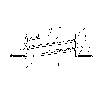
Fig. 1 shows a spout 1 comprising a spout part 3, having an outer thread 4 and
having an inlet opening 3b as well as a spout opening 3a, as well as
comprising a
flange part 2 connected to the spout part 3, wherein the flange part 2 has two
sides, an attachment side 2k as well as a rear side 2i, wherein the attachment
side
2k is oriented towards the spout part 3 and can be welded to a laminated
package
6 for fastening. Such a spout 1, without the elements referred to as 8 and 8b
is
known and is used in combination with compound material 6 which is provided
with a pre-punched hole 6a, through which hole the spout 1 is introduced and
sub-
sequently adhesively bonded to the inner side of the compound material 6. Such
a
spout 1 comprises a tubular spout part open at both sides.
Fig. 1 moreover shows a first embodiment of a spout 1 in accordance with the
in-
vention which in addition to the previously described spout has a film 8
having end
sections 8b, wherein the end section 8b ends at an end face 8a, wherein both
the
left and also the right illustrated end sections 8b are welded above and
below, this
means at both sides and in the region of the rear side 21 of the flange part
2. The
film having the end sections 8b and the end face 8a is welded to the flange
part 2
over the overall circumference in the circumferential direction, such that the
spout
opening 3a and/or the inlet opening 3b are sealed with respect to the rear
side 2i
by the film 8, preferably sealed in a gas-tight manner. The gas-tight seal is
prefer-
ably brought about by means of ultrasonic welding. In a preferred embodiment,
the
end sections 8b and the laminated package 6 are arranged mutually such that
these overlap over a distance D2, in particular in order to prevent or to
reduce a
diffusion of oxygen from the outside into the interior of the laminated
package seal
6.
It can, in particular also be seen from Fig. 1 that the spout in accordance
with the
invention, in a possible embodiment, can have substantially the same geometric
dimensions, as a so-far known spout which results in the advantage that the
spout
in accordance with the invention can be used in combination with already known
CA 02821980 2013-06-14
9
laminated packages and that the spout in accordance with the invention can be
used in already existing package plants. In this connection it is particularly
advan-
tageous that, thanks to the spout in accordance with the invention, now also
asep-
tic containers can be manufactured at package plants at which so far no
aseptic
container could be produced, provided the layer material used for the
laminated
package has an oxygen-impermeable layer.
Fig. 2 shows a further embodiment of a spout 1 which moreover has an inner
thread 7 in the inner space 3a. At the rear side 21 of the flange part 2 an
oxygen-
impermeable film 8 is arranged which is at least partially welded to the
surface or
within the rear side 2i, wherein the weld extends over the entire
circumference of
the flange part 2, so that the spout opening 3a and/or the inlet opening 3a is
sealed with respect to the rear side 2i by the film 8 covering the overall
spout
opening 3a and/or the inlet opening 3a.
Fig. 3 shows a detailed view of the left side of the spout 1 illustrated in
Fig. 2. The
flange part 2 has a recess 2g at the attachment side 2k which is intended for
the
reception of the laminated package 6. The end section 8b of the film 8 is
arranged
extending into the flange part 2, for example, in the form of a curved
extending
section 8c, such that the spacing between the end section 8b and the fastening
section 2k reduces in the direction towards the periphery of the flange part
2. In
order to achieve this the flange part 2 has a thickness reducing towards the
pe-
riphery in an advantageous embodiment, such that the mutual spacing between
the fastening section 2k and the rear side 2i reduces. Particularly
advantageously,
the end section 8b is designed inclined or extending curved with respect to
the at-
tachment side 2k, wherein the surface of the recess 2g advantageously extends
straight-lined. The nobs 2e thus represent so-called energy-direction actors
which
project over the surface of the recess 2g prior to the welding of the flange
part 2 to
the laminated package 6, wherein these nobs 2g melt during the welding, e.g.
dur-
ing the ultrasonic welding of the flange part 2 and the laminated package 6,
such
CA 02821980 2013-06-14
that the nobs 2e are no longer visible in the illustrated arrangement, which
is why
the nobs 2e are only illustrated in a doted manner. The end section 8b of the
film 8
ends at an end face 8a, wherein the distance D1 between the attachment side 2k
and/or the recess 2g and the end face 8a lies in the range of up to 0.5 mm and
preferably lies in the range between up to and including 0.1 and 0.3 mm. The
dis-
tance D1 could, however, also lie in the range of up to 1 mm. A smaller
distance
D1 has the advantage that at this position no or only a very little amount of
oxygen
can penetrate from the outside into the inner space of the laminated package
6.
Advantageously, the flange part 2 is configured such that the laminated
package 6
is welded to the attachment side 2k and/or the recess 2g and the film 8
arranged
at the rear side 2i overlap with respect to the flange part 2 in the radial
direction
mutually by distance D2 of at least 1 mm, preferably overlap by a distance of
up to
5 mm or up to 10 mm. A larger distance D2 has the advantage that it is more
diffi-
cult for oxygen to penetrate the inner space of the laminated package 6 from
the
outside. In a particularly advantageous arrangement thus a small distance D1
and
a large distance D2 are selected in order to hinder or prevent the penetration
of
oxygen.
The flange part 2 has a weld 2a at which after finishing the welding process a
sealed part 2c is formed, such that the end section 8b of the film 8 is
arranged in
the region of the sealed part 2c at both sides in the flange part 2 and the
end face
8a of the end section 8b, as well as the end section 8b is enclosed by the
sealed
part 2c. The film 8 is preferably configured as a layered material and has a
barrier
layer preferably an aluminum layer. The aluminum layer is preferably covered
on
both sides with at least a plastic layer, wherein the aluminum layer can
contact at
the end face 8a at the surface of the film 8. The end side 8a, as well as the
end
section 8b are arranged within the sealed part 2 in a gas-tight manner. In a
par-
ticularly advantageous embodiment the sealed part 2c has a curved extent,
advan-
tageously a bead-like extent. The gas-tight welding with respect to the sealed
part
2c takes place by means of ultrasound. The weld 2a extends, as partly
viewable,
CA 02821980 2013-06-14
11
over the entire circumference of the flange part 2, such that a tight
connection, in
particular a gas-tight connection, between the flange part 2 and the film 8 is
formed. Advantageously at least one further weld is provided between the
flange
part 2 and the film 8, which is indicated by a first weld 2ac, as well as by a
second
weld 2ab which are illustrated as a region. The first or second weld 2ac, 2ab
like-
wise extend over the entire circumferential direction of the flange part 2.
The first
weld 2ac is arranged in the region of the inlet opening 3b and extends along
the
entire circumference of the rear side 2i. For a secure welding of the film 8
to the
flange part 2, as illustrated in Fig. 5, an energy directing actor 21 and/or a
nob 21
is provided in order to connect the film 8 in the region of the inlet opening
3b to the
rear side 2i. This first weld 2ac is, in particular of importance also for the
reason
that the film 8 is separated by a cutting edge, in a preferred embodiment,
which
cutting edge acts on the film 8 from the side of the spout part 3. The first
weld 2ac
thus holds the film 8 in a defined position with respect to the boundary of
the inlet
opening 3b enabling a particularly precise separation of the film 8 with a
cutting
edge, since the film 8 cannot or can only marginally escape back.
Fig. 4 shows a section through an intermediate product la of the spout 1 prior
to
the welding of the film 8. The intermediate product la will subsequently also
be
referred to as a semi-finished product la. Fig. 5 shows the left side of the
interme-
diate product 1a of the spout 1, as illustrated in Fig. 4, in detail. The
flange 2 has a
nose part 2 extending along the entire circumference and projecting with
respect
to the rear side 2i which nose part 2f forms a weld point 2h in the not yet
welded
state. The rear side 2i moreover has a curved extending section 2b. At the at-
tachment side 2k circularly surrounding nobs 2e are arranged which are config-
ured as an energy directing actor 2e which, amongst other things, serves for
the
welding to the package 6. In a particularly advantageous embodiment the
thinnest
point 2n which, in the illustrated embodiment is configured as an inflection
point, is
arranged opposite an energy directing actor 2e which brings about the
advantage
that the injection mold by means of which the intermediate product la
illustrated in
CA 02821980 2013-06-14
12
Fig. 1 is preferably produced forms a wide passage in the region of the
thinnest
point 2n, such that the supply of injection molded material into the
projecting nose
part 2f is ensured. This enables the manufacture of an intermediate product 1a
having a particularly small distance between the attachment side 2k and the
thin-
nest point 2n.
The spout 1 in accordance with the invention is manufactured in an
advantageous
method such that a spout 1 is manufactured as an intermediate product 1a which
at the rear side 2i, as illustrated in Figs. 4 and 5, has a nose part 2f
extending in
the circumferential direction, projecting over the rear side 21, wherein in a
subse-
quent method step a film 8 which also covers the spout opening 3a and/or the
inlet
opening 3b, is arranged in the region of the rear side 2i enclosed by the nose
part
2f. The film 8 has the end section 8b oriented towards the nose part 2f. In a
sub-
sequent method step the nose part 2f is deformed by means of ultrasonic
welding,
as illustrated in Fig. 3, to a sealed part 2c such that the sealed part 2c
encloses
the end section 8b in the circumferential direction and the section 8b
together with
the end face 8a is welded together with the film 8 at both sides in the flange
part 2.
In a particularly advantageous method the flange part 2 is generated with a
thick-
ness reducing towards the nose part 2f, so that the distance D1 between the
film 8
and the attachment side 2k reduces for a welded film 8 at least in the region
of the
sealed part 2c. Particularly advantageously the rear side 8a is formed with a
sur-
face extending curved in the direction towards the nose part 2f.
Fig. 6 shows the completed spout 1 comprising the welded film 8 in a side
view,
wherein, in particular also the bead-like weld 2a extending in the
circumferential
direction and/or the sealed part 2c is illustrated. Fig. 7 shows the completed
spout
1 in a perspective view. Fig. 8 in a view from above and Fig. 9 in a view from
be-
low. The Figs. 2 and 3 show the completed spout 1 along the sectional line A-A
in
accordance with Fig. 8.
CA 02821980 2013-06-14
13
The spout 1 in accordance with the invention can be combined to a container
clo-
sure 9 in a plurality of embodiments. The Figs. 10 to 14 and 16 show a
possible
embodiment of a container closure 9 and its part components by way of example.
The container closure 9 and its part components preferably are composed of a
plastic, wherein the film 9 comprises a barrier layer of metal such as
aluminum.
Fig. 10 shows a perspective view of a closed container closure 9, wherein a
screw
cover 10 is visibly illustrated with a warranty band 10a and a flange 2.
Advanta-
geously, the container closure 9 in this arrangement is welded via the
attachment
side 2k to a package and/or to a container wall. Fig. 11 shows, in a
perspective
view, an embodiment of a cutting element 11 comprising an outer thread 11a, a
plurality of cutting edges 11b, a cutting wall part 11c and a longitudinal
guide 11d.
Fig. 12 shows a cross-section through the container closure 9 illustrated in
Fig. 9.
The container closure 9 comprises a spout 1 composed of a hollow-cylindrical
spout part 3, a flange 2, as well as a film 8 welded to the flange 2. The
container
closure 9 further comprises a screw cover 10 having an inner thread 10b and an
axis of rotation D and further comprises a cutting part 11 which is arranged
within
the spout part 3, wherein the cutting part 11 has an outer thread 11a and the
spout
1 has an inner thread 7 which engage with one another and are configured such
that the cutting part 11 moves, on the first time opening of the screw cover
10, by
rotation in the direction of the axis of rotation towards the film 8, such
that the cut-
ting edges 11 b penetrate into the film 8 separate this and thereby at least
partly
open it. The screw cover 10 comprises, as visible from the Figs. 13, 14 and
16, an
engagement part 10c, wherein the cutting part 11 and the screw cover 10 are
con-
figured mutually adapted with respect to one another, such that the engagement
part 10c transfers a torque onto the cutting part 11. The same reference
numerals
refer to the same features in the Figs. 10 to 14 and 16.
CA 02821980 2013-06-14
14
In an advantageous embodiment the container closure 9 is configured such that
the engagement part 10c extends in the direction of extent of the axis of
rotation
D, and such that the cutting part 11 comprises a lug 11c for the reception of
the
engagement part 10c, wherein the lug 11c is configured such that the
engagement
part 10c is stored displaceable with respect to the lug 11c in the direction
of extent
of the axis of rotation D and in this connection forms a form-fitting
connection on
the formation of a longitudinal guide 11d.
The illustrated container closure 9 has the advantage that the engagement
parts
10c are guided very well in the cutting part 11, which in turn brings about
the ad-
vantage that the engagement parts 10c can be configured very thin and light
and
only have to have a relatively small stability, such that on the manufacture
of the
screw cover 10 and, in particular of the engagement parts 10c, material can be
saved. Moreover, the container closure 9 in the assembled state forms a non-
losable fixation.
In a detailed view, similar to that of Fig. 3, Fig. 15 shows a further
embodiment of a
weld 2a of the film 8 at the flange 2. In contrast to the embodiment
illustrated in
Fig. 3, the weld 2a, as well as the end section 8b of the film 8 are arranged
dis-
placed further to the right with respect to the hollow cylindrical spout part
3, such
that a shorter distance D2 results. The flange 2 can then end after the weld
2a, or,
as illustrated in Fig. 15, extend even further towards the periphery.
The spout 1 in accordance with the invention can also be combined with a
plurality
of differently designed screw covers 10 and cutting elements 11, which have
the
properties of closing the spout opening 3a from the outside and separating the
film
8.
Fig. 17 shows a section through a further embodiment of an intermediate
product
la of a spout 1 prior to the welding of the film 8 similar to that illustrated
in Fig. 5.
CA 02821980 2013-06-14
In contrast to the embodiment in accordance with Fig. 5, the rear side 2i
extends in
a straight line. Moreover, the flange part 2 comprises a venting hole 2m which
forms a fluid-conducting connection between the attachment side 2k and the
rear
side 2i. Fig. 17 further shows a section of a sonotrode 12a which forms a part
of
an ultrasonic welding apparatus. The sonotrode 12a has a form surface 12b.
Also
the intermediate product la illustrated in Fig. 5 could have a venting hole
2m.
Fig. 18 shows the intermediate product la illustrated in Fig. 17 after the
welding to
the film 8, such that the spout 1 is formed comprising the film 8. For this
purpose,
for the arrangement illustrated in Fig. 17, the film is placed at the rear
side 2i and
thereafter the sonotrode 12a is guided towards the rear side 2i in order to
first melt
the projecting nose part 2f to a bead-shaped sealed part 2c by ultrasonic
welding
and then to deform this. The ultrasonic welding preferably takes place by
means of
a torsional welding method. However, also a longitudinal welding method could
be
employed. In Fig. 18 the sonotrode 12a is already partly retracted, such that
the
sealed part 2c is clearly visible. As illustrated, the form surface 12b of the
sonotrode 12a advantageously determines the achieved extent of the sealed part
2c. Preferably, the form surface 2b is of curve-like design in order to
achieve a
bead-like sealed part 2c. The form surface 12b can, however, also be
configured
of different extent, for example as illustrated in Fig. 19. The form surface
12b al-
ways comprises a tilted and/or transverse, oblique or radially extending part
sur-
face 12c with respect to the extent of the attachment side 2k, in order to
urge away
the material of the projecting nose part 2f in the direction towards the inlet
opening
3b, so that the nose part 2f, as illustrated in Fig. 18, is deformed to the
sealed part
2c, such that the sealed part 2c covers the end section 8b also at the outer
side.
The sonotrode 12 is preferably configured larger than illustrated and advanta-
geously comprises further form surfaces 12d which are only illustrated by way
of
indication, in order to additionally form the first weld 2ac and to deform the
energy
directing actor 21 and/or to form the second weld 2ab. The hole 2m in this
respect
16
serves for the degasing of the space present between the first and second weld
2ac, 2ab, so that no air is enclosed between the rear side 2i and the film 8
and al-
so that no air bubbles are formed.
In an advantageous embodiment material of the nose part 2f is urged in the
direc-
tion towards the inlet opening 3b during the ultrasonic welding, so that the
end
section 8b is covered with material at the side remote from the rear side 21
and in
this connection the sealed part 2c is formed, wherein the sealed part 2c is
prefera-
bly of bead-like design.
In an advantageous method a sonotrode 12a has a form surface 12b having a part
form surface 12c extending inclined and/or transverse, oblique or radially
with re-
spect to the extent of the attachment side 2k, wherein this part form surface
12c
acts on the projecting nose part 12f in order to urge material of the nose
part 12f
away in the direction towards the inlet opening 3b. Such a part form surface
12c is
illustrated in Fig. 19. Also the extent of the form surface 12b illustrated in
Figs. 17
and 18 on the left hand side has a non-illustrated, but clearly visible round
extend-
ing part form surface 12c which urges the projecting nose part 2f away in the
di-
rection towards the inlet opening 3b.
The spout 1 in accordance with the invention and/or the container closure 9 in
ac-
cordance with the invention is advantageously manufactured in a plurality of
sub-
sequently following method steps in that in a first method step the semi-
finished
product la illustrated, for example in Fig. 4, is produced and in that in a
subse-
quent method step, the spout 1 is
manufac-
tured in that the film 8 is welded to the semi-finished product 1a and in
that, as il-
lustrated for example, in Fig. 10, the spout 1 is provided with a screw cover
in a
subsequently following method step. The container closure 9 can then be con-
nected to a food container, for example, in a laminated package manufactured
with a laminated layered material in order to produce an aseptic package.
CA 2821980 2018-03-02