Note: Descriptions are shown in the official language in which they were submitted.
CA 02822272 2013-06-19
WO 2012/085138
PCT/EP2011/073665
Explosion detection method and apparatus,
stabilizing device for a vehicle,
stabilized vehicle, prepared vehicle
The invention relates to explosion detection and
to vehicle stabilization.
Vehicles may become unstable upon external
impact. A typical example for external impact is a
mine exploding below a vehicle. Amongst others, such
an explosion generates, for a certain time, a high
pressure between vehicle bottom and ground, this
pressure generating an upward force and, depending on
symmetry of position, also rotational momentum. The
upwardly directed force, depending on magnitude, may
lift the vehicle off the ground. Once off the ground,
an imparted momentum leads to rotation of the vehicle
around a horizontal axis. Naturally, this all can lead
to severe injuries of the occupants and to damage of
the vehicle.
For counteracting such events, stabilizing
devices have been proposed that detect an explosion
and generate an opposing force directed against the
upwardly directed force of the explosion.
WO 2010/067093 Al is an example for this and figure 1
shows a related arrangement. The vehicle comprises
pressure detection means 8 provided below the vehicle
and vehicle stabilizing means 2 on the roof top of the
vehicle. Upon detection of an explosion, symbolized by
9a in figure 1, the vehicle stabilizing means 2 will
be ignited and generate thereafter a downwardly
directed force counteracting the upwardly directed
force from the explosion 9a. The stabilizing means is
a rocket motor burning a propellant and generating a
1
CA 02822272 2013-06-19
WO 2012/085138
PCT/EP2011/073665
gas jet 9b in an upward direction that generates a
downwardly directed thrust.
The disadvantage of this known system is that
detection is relatively slow in that the shock wave is
only detected when it has reached the vehicle, and
that the counter measure is, in its force over time
profile, not well adapted to the force over time
profile of an explosion underneath the vehicle.
Other examples of prior art are DE 2822106,
DE 31183774, DE 10259918, DE 19013845, DE 19631715,
DE 19832662, DE 19909905, DE 202005006655, EP 1382932,
EP 1467171, RU 2003127462, US 3580354, US 3995656,
US 5012721, US 5401055, US 5765783, US 5931409,
US 6065558, US 6095459, US 6170847, US 6394738,
US 6556908, US 6588799, US 6938924, US 7494153,
US 2004/0200347, US 2005/0230176, WO 2002/039048,
WO 2004/106840, WO 2005/113330, WO 2008/063205,
WO 2009/114172, WO 2009/117648.
It is the object of the invention to provide an
explosion detection apparatus and method that is quick
and reliable in detection and thus allows a well
adapted counter measure. It is further an object of
the invention to provide a vehicle stabilization
device and method well adapted in their timings of
detection and counter measure in relation to the
timings required by the threat to be dealt with.
These objects are accomplished by the independent
claims. Dependent claims are directed on preferred
embodiments of the invention.
2
CA 02822272 2013-06-19
WO 2012/085138
PCT/EP2011/073665
An explosion detection apparatus comprises a
first path pickup means for picking up a first forward
path portion, preferably ahead of the vehicle, and
generating first path data on said first forward path
portion that will be stored, a second path pickup
means for picking up a second rearward path portion
behind the first forward path portion underneath the
vehicle and generating second path data, comparing
means for comparing at least a portion of the first
data with at least a portion of the second data in
accordance with motion data of the vehicle, and a
first explosion judging means judging that an
explosion has occurred when a certain condition
amongst the compared data is met.
Basically, a certain path portion is observed a
first time when it is at a more forward position
relative to the vehicle, preferably ahead of the
vehicle before the vehicle passes it, and is observed
later a second time when it is more rearward when the
vehicle passes it. The two observations are compared.
A deviation amongst them may be a sign of an explosion
taking place underneath the vehicle.
The signals to be evaluated for the situation
underneath the vehicle reach the vehicle with the
speed of light, and thus reach the vehicle before a
shockwave will reach the vehicle. Accordingly, the
explosion is detected before its impact has reached
the vehicle. Thus, valuable time is gained so that the
counter measure can, already because of the degree of
freedom gained from the time advantage, be better
adapted to the impact to be counteracted.
3
CA 02822272 2013-06-19
WO 2012/085138
PCT/EP2011/073665
Another explosion detection apparatus comprises a
first detection device for detecting an explosion
based on electromagnetic waves or based on path
pickup, a second detection device for detecting the
explosion based on a mechanical quantity such as
pressure, angular or translation or acceleration, or
bending, and a second explosion judging means
receiving the detection results from the first and
from the second detection device and judging that an
explosion has occurred in accordance with the received
detection results.
Such an explosion detection apparatus uses
quantities detectable only when the shockwave has
reached the vehicle (pressure, acceleration,
deformation, relative movement). It may be used in
addition to, or instead of, the earlier mentioned
apparatus. By evaluating both information coming with
the speed of light (electromagnetic waves) and
information upon impact on the vehicle the detection
results become more reliable and may comprise also a
quantitative measurement on the impact experienced by
the vehicle. The quantitative measurement may be used
for making quantitative determinations for operating
counter measures, such as determining the timing of
counter measures and/or determining a selectable
quantity of counter measures.
Explosion detections may be conducted
periodically or with a maximum cycle time. Such a
maximum cycle time or period may be less than 50 psec,
less than 20 psec, less than 10 psec or less than
5 psec. Assuming that in a typical scenario it takes
about 100 psec for an explosion shockwave to reach a
vehicle, the mentioned periods allow completion of a
4
CA 02822272 2013-06-19
WO 2012/085138
PCT/EP2011/073665
full explosion detection cycle within the mentioned
delay of 100 psec so that, when electromagnetic
radiation is used, detection can be accomplished
before the shockwave reaches the vehicle.
Explosion detection means based on
electromagnetic radiation may comprise radar equipment
monitoring the path under the vehicle, particularly
also the underground below the path surface, light
equipment or laser equipment evaluating transmitted
and/or reflected and/or scattered light or laser light
in the space underneath the vehicle, radio frequency
equipment monitoring received radio frequencies,
preferably in one or more predetermined frequency
bands, or infrared detection in a given infrared range
(near, mid, far). Likewise, explosion detection may be
accomplished by motion detection at corresponding path
portions within sequentially scanned or captured and
pixeled images of a path section. The subject of
observation and motion detection is then the surface
of the considered path portion. When the surface
exhibits a significant upward motion, this is taken as
an indication of an explosion. Regular motion (forward
driving movement) of the vehicle is taken into account
for finding corresponding path portions in consecutive
images. One or more pickups (cameras) of appropriate
fields of view may be used for capturing the path
portion underneath the vehicle.
The mechanical detection means may comprise one
or more different means such as a pressure sensor, an
acceleration sensor, relative motion detection amongst
vehicle components, one or more gyroscopes, one or
more proximity sensors, or a crush element. It may
also comprise deformation detection or bending
5
CA 02822272 2013-06-19
WO 2012/085138
PCT/EP2011/073665
detection by appropriate means such as strain gauges
or fibers conducting light or laser light and attached
to a vehicle component, particularly the vehicle
bottom, changing its transmission characteristics upon
deformation so that monitoring transmitted light gives
information on a possible impact.
An explosion detection method comprises the steps
of picking up a first forward path portion, preferably
ahead of the vehicle and generating first data
describing the picked-up first forward path portion,
storing the first path data, detecting motion of the
vehicle and generating motion data, picking up a
second rearward path portion underneath the vehicle
and generating second path data, comparing at least a
portion of the first data with at least a portion of
the second data in accordance with the motion data,
and judging that an explosion has occurred when a
predetermined difference between the compared data has
been found.
A stabilizing device for a vehicle comprises an
emitter having emitting means for emitting material
and attachment means for attaching the emitter to a
structural part of the vehicle, and has detection
means for detecting an external impact, and has
triggering means for triggering the emitter in
accordance with the detection result from the
detection means. The detection means may be an
apparatus as described above or may be another
apparatus able to detect the explosion and/or the
resulting external impact on the vehicle.
The triggering means may have timing control
means for controlling timing of triggering the emitter
6
CA 02822272 2013-06-19
WO 2012/085138
PCT/EP2011/073665
upon explosion detection. Particularly, triggering of
the emitter may be set at a predetermined time after
detection, or set to be within a predetermined time
window after detection. When explosion detection based
on radiation is utilized, the time window may be
20 usec to 200 psec after detection.
Plural emitters may be provided that are
separately ignitable and that are mounted at different
portions of the vehicle. The triggering means is
adapted to selectively/separately trigger one or more
or all of the emitters, preferably also
selectively/separately in time.
One or more of the emitters may be mounted on a
side wall (left side, right side) of the vehicle, and
one or more of the emitters may be mounted on the roof
top, then preferably along the center line of the
vehicle in driving direction, as seen from above.
The device may further comprise means for
automatic messaging and sending information through an
appropriate wireless channel upon detection of an
explosion to a command centre for further
processing/use and/or may comprise means for actuating
safety devices inside of the vehicle.
The stabilizing device may also be designed as a
stand alone device, i.e. without external electric or
electronic components. The detection means may be a
crush detector preferably at or inside the emitter,
and the triggering means may be a stab detonator
provided in the emitter.
7
CA 02822272 2013-06-19
WO 2012/085138
PCT/EP2011/073665
Likewise, more or less sophisticated control
equipment may be provided, be it dedicated hardware or
be it the general control hardware of the vehicle
running certain routines/software. The controller, be
it dedicated hardware or the general vehicle control
system, may comprise a sequential controller, a field
programmable gate array (FPGA), two or more parallel
processing units, a regular computer such as a PC, or
the like.
A stabilizing method for stabilizing a vehicle
against the effect of an external impact comprises
detecting an explosion, upon detection emitting
material in an upward direction.
Also part of the invention is a vehicle adapted
for mounting the mentioned stabilizing device, but not
having all of its components. In training or in civil
situations it may, for example, be desirable to drive
the vehicle without active/critical chemical
substances and without unnecessary masses attached to
it. So, the vehicle may comprise mounting structures
for the emitter, and/or may comprise wiring required
for operating the emitter and/or may comprise an
explosion detection apparatus or mounting portions for
it.
The vehicle may comprise bulkheads inside the
vehicle compartment for reinforcing the lower corners
of the vehicle compartment. Seen from the top, an
emitter may be provided at the outside side wall of
the vehicle at a position where inside the vehicle a
bulkhead is provided. The emitter may even be
connected to the bulkhead.
8
CA 02822272 2013-06-19
WO 2012/085138
PCT/EP2011/073665
In the following, embodiments and features of the
invention will be described with reference to the
attached drawings in which
figure 1 shows prior art,
figure 2 shows a first detection apparatus
schematically,
figure 3 shows a second detection apparatus
schematically,
figure 4 shows an overall controller and an
emitter,
figure 5 shows a more detailed schematic view of
a triggering device,
figure 6 shows an implement of an emitter,
figure 7 shows mounting possibilities of
emitters,
figures 8 and 9 shows bulkheads and their use in
conjunction with the invention.
In the following description, described features
shall be deemed combinable with each other also when
this is not explicitly said, as far as a combination
is not excluded by technical reasons. Disclosure of
apparatuses and apparatus features shall be understood
also as disclosure of method or methods features
implemented by the respective apparatus or apparatus
features, and vice versa. Same numerals in the various
figures denote same components.
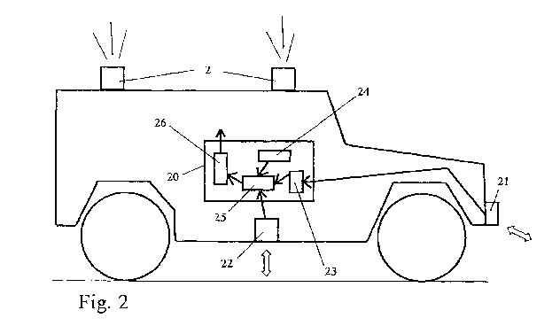
Figure 2 shows a schematic side view of a vehicle
carrying an explosion detection apparatus. The
apparatus comprises a first path pickup means 21 and a
second path pickup means 22. The first pickup 21 looks
ahead of the vehicle in driving direction, and may
also look somewhat sideways. It may be mounted
9
CA 02822272 2013-06-19
WO 2012/085138
PCT/EP2011/073665
somewhere at the front of the vehicle and may have a
field of view of not less than 450 or 60 , preferably
centered around the forward direction. It may be a
first camera generating pixeled image data. The second
pickup 22 looks below the vehicle and may be a second
camera generating pixeled image data. It also may have
a field of view of not less than 45 or 60 or 90 .
Regarding mounting, it may be sufficient that the
first pickup means 21 monitors a path portion ahead of
that monitored by the second pickup means 22. The
first pickup means may also be provided below the
vehicle. Instead of pixeling cameras, a scanning
device may constitute the first and/or second pickup
means 21, 22, e.g. a laser scanner.
Not shown image processing means may extract
features from said picked up signals and may lead to
data that may describe the path of the vehicle in the
three dimensions. The two pickup means 21 and 22 may
generate qualitatively same data, but of course, at
the same time, of different path portions as
respectively seen by them.
The first pickup means 21 looking forward/ahead
generate data that are stored in a memory 23. The data
from the second pickup means 22 may also be stored or
may be used in real time. Motion detection means 24
tell the system regular motion data of the vehicle
such as the vehicle speed or curve radius. At least
parts of the data from the second pickup means 22 are
compared with corresponding data (i. e. data
describing the same path portion) from the first
pickup means 21 stored in memory 23. Finding the
corresponding data in the first path data is made with
reference to the data from the motion detection means
CA 02822272 2013-06-19
WO 2012/085138
PCT/EP2011/073665
describing which distance and which direction
(straight, curve) the vehicle has traveled meanwhile.
Real-time or recently obtained data from the second
pickup 22 are compared with corresponding earlier
obtained data from the first pickup 21, the compared
data taken such that they describe the same path
portion.
The comparing means compare the corresponding
data from the first pickup means 21 and from the
second pickup means 22. In a stable situation both
data should be substantially the same so that a
corresponding comparison should not show a difference.
Naturally, in real environments a difference will
practically always be given. Accordingly, the
comparing means 25 may give quantitative difference
data (quantitative measure) indicating how different
the compared data are. A first judging means 26
receives the result from the comparing means 25 and
judges that an explosion has occurred when the data
from the comparing means 25 match a certain criterion,
for example exceed a predetermined threshold. The
result from the first judging means 26 can then be
used for other measures, such as triggering the
emitters, triggering automated messaging, activating
internal safety devices such as airbags, seatbelt
fasteners, intelligent clothing or the like. The
judging means 26 may forward the result from the
comparing means 25 to the emitter triggering means in
parallel to a judgment result.
Instead of providing two separate path pickup
means 21 and 22, also only one pickup means 22 looking
below the vehicle may be provided, such as one or more
cameras with an appropriate field of view, and the
11
CA 02822272 2013-06-19
WO 2012/085138
PCT/EP2011/073665
comparison for detection is made amongst different
pickups (images) from the second pickup means, again
with reference to motion data describing the regular
vehicle movement as described earlier, for finding
corresponding portions in the various images. Motion
detection algorithms may be used.
The comparing means may have filtering means for
recognizing, and discarding from detection, uncritical
path surface modifications between first and second
pickup, such as tire tracks generated by the vehicle
itself when driving a curve, stones tossed into the
path by the vehicle or the like. Filtering may
comprise making a second comparison after a first
comparison showed a significant difference between
first pickup and second pickup. Since the second
pickup means has also a certain field of view,
comparisons may also be made amongst different pickups
from the second pickup means, again with reference to
motion data describing the regular vehicle movement.
The hardware may be dedicated hardware or may be
a routine running on otherwise provided hardware. In
view of processing speed, data amount, etc., dedicated
hardware is preferred. The relevant information,
namely the path appearance below the vehicle picked up
by the second pickup means 22 reaches the vehicle, and
particularly the pickup means 22, with the speed of
light, and accordingly well before the impact from the
explosion reaches the vehicle. Then, processing speed
of the hardware becomes the bottleneck. Assuming an
average value of around 100 psec for the shockwave of
an explosion reaching the bottom of an average
vehicle, cycle time for path pickup and comparison is
preferably less then one of the values of 50 psec,
12
CA 02822272 2013-06-19
WO 2012/085138
PCT/EP2011/073665
20 psec, 10 psec or 5 psec, depending on hardware.
Hardware may be a regular computer or a parallel
processing installation or an FPGA.
Valuable time is gained with quick explosion
detection as described above. The gained time may be
used for timely triggering counter measures, and/or
for making further determinations for determining an
appropriate response.
Figure 3 shows another detection apparatus. It
comprises a first detection device 31 and a second
detection device 32. The first detection device 31
utilizes electromagnetic waves including imaging based
on path pickup as described, e.g., above. The second
detection device 32 may be a qualitatively different
detection apparatus and/or may also use
electromagnetic waves or may use a mechanical quantity
reflecting an evolving explosion. A second explosion
judging means 33 receives the detection results from
the first detection device 31 and from the second
detection device 32 and derives an overall detection
result therefrom. It may include means 34 for
generating a quantitative measure for the explosion.
The quantitative information may include one or more
data describing strength of the explosion, the
location (such as left side, right side, front, rear,
center), the experienced momentum (i.e. rotational
impact), and the like.
By combining detection results from plural, and
preferably qualitative different detection devices,
the resulting data of the detection is more reliable,
is less prone to faulty detections and is richer in
information. Countermeasures can then be adapted
13
CA 02822272 2013-06-19
WO 2012/085138
PCT/EP2011/073665
quantitatively and qualitatively to the detected
explosion.
Examples for the first detection device 31
utilizing electromagnetic waves is radar equipment,
monitoring the ground underneath the vehicle, possibly
penetrating also the ground below the road surface
(underground). It may also comprise a combination of
light/laser light emission and corresponding detection
for detecting one or more of transmitted and/or
reflected and/or scattered light in a space underneath
the vehicle. It may also comprise radio frequency
monitoring. Explosives, upon exploding emit
characteristic electromagnetic radiation that can be
detected and evaluated. The radiation falls in one or
more known frequency bans. Likewise, microwave
detection and/or infrared detection may be utilized,
preferably in the near infrared range (0,8 pm to
1,5 pm wavelength), and/or in the mid-infrared range
(1,5 pm to 6 pm) and/or in the far infrared range
(6 pm to 40 pm). A thermopile or thermocouple may be
used for this. Likewise, particle detectors (electron
detectors) or photon detectors may be used, preferably
on a semiconductor basis. A Doppler device or system
based on radio frequencies may be used. Likewise, an
apparatus as described with reference to fig. 2 may be
used as first detection device 31.
The second detection device 32 may comprise one
or more means such as a pressure sensor provided on
the vehicle and detecting ambient pressure that
naturally rises when a shockwave hits a vehicle. It
may also comprise an acceleration sensor or a relative
motion detector for detecting relative motion amongst
certain vehicle components. Gyroscopes may also be
14
CA 02822272 2013-06-19
WO 2012/085138
PCT/EP2011/073665
provided for detecting rotational movement or
acceleration. Likewise, approximate sensor or crush
element may be used. Similarly, deformation of vehicle
components such as a bottom plate or a particular
shielding plate may be monitored by appropriate means,
such as strain gauges or light fibres that change
their transmission characteristics upon deformation.
They may conduct light from a light source provided at
one end of the fibre and may have a sensor with
subsequent evaluation at the other end of the fibre.
The fibre itself is firmly attached to a component,
deformation of which is to be monitored, such as the
bottom plate or a shield.
Generally speaking, one or more or all of the
sensing devices described above that are exposed to
the environment can be provided with cleaning means
and/or with means for preventing adherence of dirt and
dust for avoiding the sensors being blocked in use.
Sprinkler means or means for supplying compressed air
may be provided for this purpose.
Figure 4 shows an example of a stabilizing
device. It comprises an emitter 2 that in turn
comprises an active substance such as explosive or
combustible material 43, preferably one or more
outlets or nozzles 42 for emitting the reaction
product of explosion or combustion, and attachment
means 44 for attaching the emitter 2 to a structural
part of the vehicle. It further comprises a container
structure 49 for accommodating the explosive or
combustible material 43 and preferably the nozzles 42.
It may also comprise some kind of closing 49a that can
easily be removed by the material to be ejected.
15
CA 02822272 2013-06-19
WO 2012/085138
PCT/EP2011/073665
The emitter 2 may eject a reaction product of the
active substance 43. The emitter may be a thruster
generating thrust in a downward direction by ejecting
in an upward direction through said outlets or nozzles
of a combustion chamber reactive components obtained
from combusting material 43. Thrust is generated as
reactive force from the ejection of the mass of the
reactive material, and is generated by pressure
differences in the pressure chamber.
Instead of an active material 43, the emitter 2
may also hold a compressed fluid, such as gas in a
high pressure container, again to be released upon
activation thorough openings or nozzles.
Likewise, it is conceivable to provoke in the
emitter a dust explosion of an appropriate material
for accomplishing the desired ejection.
A controller comprises an explosion detection
apparatus 20 that may be built as mentioned above and
triggering means 45 receiving the detection result
from the detection apparatus 20 and connected to the
emitter 2, and particularly to some kind of igniting
means or detonating means provided at or for said
explosive or combustible material 43. The detection
means 20 may also start an automated messaging means
46 for automatically dispatching a message after
detecting an explosion through an appropriate wireless
channel, the message, for example, containing position
data of the vehicle, severeness of the explosion, and
the like. Likewise, activation means 47 for safety
devices at or within the vehicle, such as airbags,
seatbelt fasteners, intelligent clothing, may receive
information from the explosion detection means 20.
16
CA 02822272 2013-06-19
WO 2012/085138
PCT/EP2011/073665
40 symolizes an igniter or detonator for the
active material 43. It may be an electrical or a laser
igniter or detonator. It receives its triggering
signal from the triggering means 45 preferably through
electrical wiring.
Figure 5 shows triggering means 45 for the
emitters 2. Shown is an embodiment with plural
emitters 2a to 2e. They can individually be triggered,
and accordingly, the triggering means 45 is adapted to
individually trigger them. The individual triggering
may include both the decision whether or not to
trigger a device, and if yes, when to trigger it.
Accordingly, the triggering means 45 may have timing
means 51 and may receive information from the
detection apparatus 20. It may particularly receive
information from the means 34 for generating a
quantitative measure. In accordance with qualitative
and quantitative indications about the detected
explosion, the timing means 51 may generate triggering
signals for one or plural emitters 2. It is pointed
out that it may be decided that not all emitters 2 are
ignited. Some of them may remain ununsed. Likewise,
ignition timing of several ignited emitters 2 may be
different.
The triggering means 45 may be formed as a unit
with the hardware of the detection apparatus 20 or may
be separated therefrom, connected to the detection
apparatus 20 through appropriate wiring. At the
respective emitters 2, respective igniters or
detonators may be provided that may be electrically
activated by appropriate signals from the triggering
means 45. Accordingly, wiring 35 may be provided
17
CA 02822272 2013-06-19
WO 2012/085138
PCT/EP2011/073665
between each of the emitters 2 and the triggering
means 45.
Figure 6 shows a close view of an emitter 2. It
may have a container-like structure with a container
49 that may have side walls and a bottom wall. 44 are
attachment means for attaching the emitter 2 to a
structural part of the vehicle. It may, in a simple
case, be a flange with a through-hole for fastening
the emitter 2 with screws to prepared portions of the
vehicle. The container structure may have an opening
on the top that may be closed by a weak closure 49a,
such as a lid or a cap. The weak closure 49a is
constructed such that it is automatically removed when
the emitter 2 is activated.
The container 49 holds the active substance 43,
preferably an explosive or a combustible material.
When activated, reaction products may escape through
openings 42 of an internal wall 63. The internal wall
63 may be provided on top of the active material 43
and may define a combustion chamber together with the
other walls of the container structure 49. The
internal wall 63 may have plural openings 42. They may
be designed as one or more nozzles. The openings or
nozzles 42 release reaction products of the active
material 43 after its activation/ignition/detonation.
The design is such that the emitter 2 releases the
reaction products in a more or less upward direction
of figure 6, so that thrust is generated in a downward
direction.
Figure 6 shows an embodiment where the emitter 2
is constructed as standalone device, meaning that both
explosion detection and triggering of activation of
18
CA 02822272 2013-06-19
WO 2012/085138
PCT/EP2011/073665
the active material 43 is made at or inside the
emitter 2. 61 symbolizes a detector, and 62 a
triggering means and igniter/detonator upon detection.
Detector 61 may be a crush element or crush switch
that mechanically modifies upon experiencing
significant acceleration. It may cause an igniter or
detonator 62 to activate the active material 43.
Activation may be electrically or mechanically or
chemically. Such an embodiment does not require
sophisticated detection and does not require external
wiring or external components.
Figures 7, 8 and 9 show possibilities for
arranging emitters 2 at a vehicle. Figure 7 is a top
view on the vehicle. 71 symbolizes a center line of
the vehicle in driving direction. The right side is
assumed to be forward in driving direction, as
indicated by the arrow. 72 symbolizes wheels of the
vehicles. One or more emitters 2c, 2d and 2e may be
provided on the rooftop of the vehicle. They may
preferably be arranged along the center line 71.
Besides, one or more emitters 2a, 2b may be provided
on left and right outer side walls of the vehicle. It
is noted that also these sideways emitters 2a, 2b may
be constructed to generate a downward thrust, i.e. a
thrust directed towards the ground surface. However,
they also may be designed to generate a sideways or
diagonal thrust, if it is desired to compensate for
sidewards impact. Also one or more of the emitters 2c,
2d and 2e on the vehicle roof may be designed to
generate sideways thrust. On each side of the vehicle,
front and rear side included, one, two or more
emitters 2 may be provided.
19
CA 02822272 2013-06-19
WO 2012/085138
PCT/EP2011/073665
The arrangement seen in a top view may also be
different from that shown in fig. 7. For example,
emitters may be on the roof top of the vehicle close
to corner portions thereof. Likewise, they may be on
the roof top at or close to the elongated edges in the
middle between corners limiting the respective edge.
Likewise, emitters may be provided on the roof top
along two arrangement lines parallel to the center
line 71, but shifted against the center line 71 to the
left and to the right, respectively, so that, for
example, emitters sit on the roof top at, e.g., 25%
and 75% of the vehicle width.
Figure 8 shows a more detailed arrangement. It is
a schematic top view with the roof of the vehicle
removed. 81 may be occupant's seats which may be
provided in the rear compartment of the vehicle. 81a
symbolizes the driver's seat. 82 symbolizes one or
more bulkheads provided for reinforcing the structure
of the vehicle. The bulkheads may be provided in a
plane perpendicular to the forward direction (left-
right in figure 8). They may be provided to reinforce
the lower corners of the vehicle compartment, as shown
in figure 9. The bulkheads may be metallic structures
fitting into the corner(s) to be reinforced. In a
widthwise direction, they may cover at least 20 % of
the width W of the vehicle, and they may cover at
least 20 % or 40% of the height H of the vehicle
compartment. They may be attached to the side walls
and to the bottom structure of the vehicle by screws,
welding or the like. The bulkheads 82 may comprise
cutouts or openings 84 for saving weight.
As shown in figure 8, emitters 2a and 2b mounted
at the outer side wall of the vehicle may be mounted,
CA 02822272 2013-06-19
WO 2012/085138
PCT/EP2011/073665
seen in a longitudinal direction (left-right in figure
8) at position where bulkheads 82 are provided.
Further, they may be connected to the bulkheads 82,
either directly through, or indirectly via. the
vehicle side wall. This ensures that the emitters 2
find a strong abutment, and the thrust generated by
them is guided towards the bottom structure of the
vehicle.
As shown in figure 9, opposing bulkheads 82a, 82b
may be connected with their lower parts to each other
and possibly also to the bottom portion of the vehicle
through appropriate connecting means 83. This ensures
that when receiving a load, the bulkheads 82 do not
collapse towards each other.
If other reinforcing structures than bulkheads 82
are provided at or in or on vehicle side walls, the
sideways emitters 2a, 2b may also be provided at or
close to such other reinforcing structures and may
directly or indirectly be connected thereto.
One aspect of the application is the stabilizing
device as described above, but separate from the
vehicle. It may be manufactured and marketed
separately from a vehicle. It may then comprise the
emitter 2 and appropriate detection installations 20
and triggering means 45 or software for implementing
such functionalities on other hardware. Another aspect
of the invention is a vehicle provided with the
mentioned stabilization device. Yet another aspect of
the invention is a vehicle prepared for receiving the
stabilizing device, but not incorporating the
stabilizing device, or not incorporating it
completely. It may have dummy components instead.
21
CA 02822272 2013-06-19
WO 2012/085138
PCT/EP2011/073665
A vehicle prepared for obtaining the
stabilization device may comprise fixation means for
attaching the emitter 2 to structural parts of the
vehicle. It may further comprise wiring 35, for
example for igniting/detonating/activating the emitter
2, and/or towards sensors and path pickup means. It
may also comprise containing structures similar to
numeral 49 shown in figure 4, that are, however, not
filled with active substances.
A prepared vehicle may also comprise dummies for
experiencing the spacial situation as if real
components were mounted. Such a dummy may particularly
have the outer shape, and take the position, of an
emitter. The dummy may be made of a cheap material
only provided for the purpose of experiencing and
training in a special situation same as or similar to
that when the real stabilization device is mounted.
The invention has been described so far as being
applied to ground vehicles. It is not limited to this
field. It may also be used for other artifacts to be
protected such as ships or airplanes or for stationary
structures such as buildings. An emitter 2 may be
located on an outer surface of the artifact to be
protected. Upward and downward directions described
above with reference to vehicle protection may then
generally be replaced by opposing directions that may
also be horizontal or may have horizontal components.
The explosion detection apparatus is then designed to
detect explosions in the desired area, and the
arrangement of emitters 2 is such that they act
against the detected impact, particular develop thrust
22
CA 02822272 2013-06-19
WO 2012/085138
PCT/EP2011/073665
in a direction against the detected impact to be
countered.
The described embodiments and examples are merely
examples/embodiments of the invention. The invention
could have other embodiments within the scope of the
main invention as described in this specification.
23