Note: Descriptions are shown in the official language in which they were submitted.
CA 02822857 2013-06-25
METHOD AND CONTRIVANCE FOR THE BREAKING-UP OF A FRESH AND HOT
COKE BATCH IN A RECEIVING CONTAINER
[0001] The invention relates to a method and a contrivance for the breaking-
up of a
fresh and hot coke batch in a receiving container with movable plate segments,
with the
coke batch being transported in the receiving container of a flat-bed transfer
car to a
quenching tower, where the coke batch is cooled down to ambient temperatures
by using
movable plate segments so that the coke structure loosens up and gap-like
cavities form
in the compacted coke batch, and on account of these gap-like cavities an
increased
amount of water can flow into the inside of the coke batch during the
subsequent quench-
ing process, the reduced quenching time and the lower water consumption for
coke
quenching resulting in a higher economic efficiency of the method, a higher
coke quality
and a lower emission load for the environment. The invention also relates to a
contriv-
ance for applying this method.
[0002] Conventional horizontal-type coke-oven chambers are equipped with so-
called coke transfer machines on the coke side of the coke-oven batteries,
such ma-
chines being used for operations to be performed in connection with the coke-
sided push-
ing of the carbonised coke. Normally the coke quenching device is a quenching
car which
can be ¨ at least partly ¨ moved separately underneath the coke transfer
machine. The
quenching car typically includes a receiving container which takes up the coke
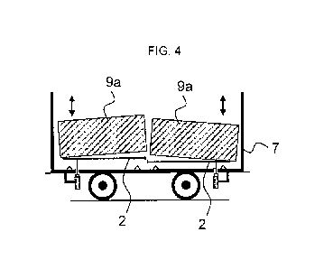
from the
coke-oven chamber and takes it to the quenching tower. Between the receiving
container
and the coke-oven chamber there is frequently a coke transfer machine which,
in a sim-
ple case, may consist of a wharf or a sloped plate and ensures, by integral
suction devic-
es, that the emissions produced when the coke drops out of the oven are
evacuated into
a dust extraction system, thereby minimising the environmental load. The
quenching car
typically travels on rails and can be moved directly below the quenching tower
by means
of a transport device. The quenching tower is a wet-quenching tower according
to an em-
bodiment frequently used but it can also be a dry-quenching tower.
[0003] The coal-to-coke carbonisation is frequently carried out in so-
called heat-
recovery or non-recovery-type coke-oven chambers. Modern coke ovens of the
heat- re-
covery or non-recovery-type are not equipped with such extracting transfer
machines. Af-
ter carbonisation, the coke is here pushed into a flat-bed quenching car which
is on the
same level as the lower edge of the oven, thereby avoiding the production of
emissions
when pushing the coke, as the coke cake does not drop vertically out of the
oven.
CA 02822857 2013-06-25
[0004] In the practice of coke-oven engineering, the coke is considered
fully carbon-
ised if the content of volatile components is below 1.8 weight percent (wt.-
%). These vola-
tile residual components are distributed heterogeneously inside the coke batch
and nor-
mally burn if they are exposed to an oxygen-bearing ambient atmosphere. The
coke is
normally pushed into this quenching car at average temperatures between 900
and 1100
C. When pushing has been completed, the quenching car is moved to the
quenching
tower. In the quenching tower the coke is then cooled to temperatures of
approx. 100 C
by supplying water.
[0005] A typical contrivance including a quenching car for wet quenching is
de-
scribed in DE 1253669 B. The invention relates to a contrivance for the
quenching of
coke that has been discharged from horizontal coking chambers, the contrivance
consist-
ing of a stationary quenching compartment with stack-like part and travelling
along the
oven battery on the coke side or being supplied from a receiving car or from a
receiving
car for glowing coke, and a coke receiving compartment which is followed by a
circulating
conveying grid with spraying system on top, in which tube bundles containing
heatable
process fluid are installed above the conveying grid between the device for
controlling the
height of the coke layer and the spraying system, these tube bundles possibly
communi-
cating with the known tube bundles of the coke receiving compartment.
Embodiments of
a quenching car and its control system are disclosed by WO 2006/089612 Al, US
5564340 A and EP 964049 A2.
[0006] There are also embodiments where the coke is quenched from below by
sup-
plying water. Such embodiment is also called "bottom quenching". It is also
common
practice to combine both quenching methods. Typical embodiments of a dry
quenching
method are disclosed by WO 91/09094 Al and EP 0084786 Bl.
[0007] Transport of the coke can be carried out in quenching cars of the
flat-bed type
or quenching cars with receiving container. Flat-bed quenching cars are
described in CN
2668641 Y, for example. Quenching cars with receiving container are described
in
US 5564340 A, for example. The coke does not burn at first, as an ash layer of
up to 30
mm forms at the upper edge of the coal batch by combustion of the uppermost
coal lay-
ers during the first hours of the carbonisation process due to direct heating.
This ash layer
largely protects the coke from further combustion during transport to the
quenching tower.
In this way the emissions remain within tolerable limits and can be sucked off
during the
transport by suitable extraction devices if required.
2
CA 02822857 2013-06-25
[0008] Coke quenching systems have normally been designed assuming that
coke
densities are between 400 and 600 kg * M-3 and the vertical height of the coke
cake is
approx. 1000 mm. To improve the economic efficiency, the initial coal
densities of 850 to
1200 kg * M-3 have recently been raised. The coke cake densities obtained from
carboni-
sation are therefore above the known range of 400 to 600 kg * m-3 and also
cause sealing
of the coke cake surface. The result is that the quenching water cannot
penetrate vertical-
ly into the batch or only with delay.
[0009] The coke is then quenched in the quenching tower. The high degree of
com-
paction of the coal cake and of the coal cake obtained from carbonisation
makes it im-
possible for the quenching water to penetrate vertically into the batch or
only with delay.
In this way the cooling effect is retarded.
[0010] An additional impedance to the effective cooling of the fresh coke
batch is the
so-called "Leidenfrost effect". As the temperature of the coke batch is high,
the water im-
pinging on the surface of the hot coke will evaporate instantaneously. As a
result a coat of
water vapour forms around the coke pieces preventing the entry of further
water. The wa-
ter impinging on the surface of the coke forms a protective vaporous coat for
a limited pe-
riod of time and protects the coke from direct heat transfer. In this way the
water cannot
penetrate efficiently into the inside of the coke and therefore flows off
laterally not reach-
ing the inner coke layers.
[0011] In this way the quenching water is distributed unevenly across the
entire vol-
ume of the coke batch. As this also results in uneven cooling by the quenching
water, the
temperature distribution across the coke batch will likewise be uneven. Hence
there will
still be parts of the coke cake after quenching that show a coke temperature
of more than
100 C. This is a significant problem when processing and using the coke
downstream as
coke batch portions of temperatures above 100 C can damage transport and
conveying
belts which are frequently made of hard rubber or plastics. The quenched coke
will thus
also consist of partial batches the water content of which is above 3 wt.- /0.
An elevated
water content of more than 3 wt.-% in the coke is also a problem as the water
will dimin-
ish the product quality of the raw iron in the downstream blast-furnace
process.
[0012] The aim in the processes of pushing and quenching of produced coke
cakes
is to reduce the emissions or to eliminate them as completely as possible. The
emissions
can be reduced by transporting the coke cake to the quenching tower after the
end of the
3
CA 02822857 2013-06-25
pushing process without any further mechanical treatment. The ash layer
produced by the
combustion of the uppermost coal layers largely protects the coke from further
combus-
tion during transport to the quenching tower and does not produce any
emissions unless
it is whirled up.
[0013] It is therefore the aim to provide a method which allows quenching
and cool-
ing of the glowing coke in the quenching tower immediately after the end of
the pushing
process while preventing uneven temperature distribution or water content in
the coke
batch and at the same time reducing pollution.
[0014] The invention achieves this aim by a method that uses a plate above
the bot-
tom plate of the receiving container of a quenching car, the plate being
subdivided into
movable segments which are moved or lifted against one another above the
bottom of the
receiving container by a controllable driving unit shortly before or during
the quenching
process so that the fresh coke batch rips up and forms additional gaps,
channels and
clear edge areas in the coke into which the cooling agent can flow from the
cooling agent
nozzles arranged above, and the cleared areas of the coke batch can be wetted
by the
cooling agent.
[0015] Thus a method is provided which actively supports the process of
quenching
a coke cake during the quenching in the quenching tower so that the quenching
process
can be adapted to meet the conditions of the coke cake and of the quenching
tower.
[0016] Particular claim is laid to a method for breaking up a fresh and hot
coke batch
in a receiving container, according to which
= the coke-oven chamber of a heat-recovery or non-recovery-type coke-
oven bank is charged with coal for carbonisation, this coal being carbon-
ised in operating cycles, and
= the coke is pushed by a pusher machine in form of a compact and solid
coke cake after the carbonisation process from the coke-oven chamber in-
to the receiving container of a quenching car, and
= the coke is transported in the quenching car to a quenching tower where
it
is cooled to ambient temperature by means of a cooling agent,
4
CA 02822857 2013-06-25
and which is characterised in that
= movable segments of a plate are moved or lifted against one another
above the bottom of the receiving container by at least one controllable
driving unit shortly before or during the quenching process,
= so that the fresh coke batch rips up and forms additional gaps, channels
and clear edge areas in the coke into which the cooling agent can flow
from the cooling agent nozzles arranged above, and the cleared areas of
the coke batch can be wetted by the cooling agent.
[0017] As the coal batch breaks up on account of the movement of the
movable
segments of the plate on the bottom of the receiving container, the cooling
agent can
reach the cleared partial areas of the coke cake, the total surface area of
which is consid-
erably enlarged by the break-up of the coal cake. In this way the quenching
process is a
lot more intensive. At the same time the pollution is reduced as the harmful
ash and coke
dust whirled up by the break-up of the batch is already washed out by the
water trickling
down from the vaporous atmosphere in the quenching tower and hence does not
get into
the environment. If required, the ash and coke dust can later be submitted to
a down-
stream treatment in the sedimentation basin.
[0018] According to an embodiment of the invention the surface segments are
de-
signed such that they can be moved horizontally against one another in
longitudinal or
transversal direction of the bottom of the receiving container. For this, at
least one of the
surface segments is pulled out of its resting position by 5 to 400 mm. In
another embodi-
ment of the invention the surface segments can be moved against one another in
vertical
direction, and at least one of these surface segments can be lowered or lifted
from its
resting position by 5 to 600 mm. A flat-bed quenching car of a heat-recovery
or non-
recovery coke-oven system normally has a car width between 2.0 and 4.5 m and a
car
length between 10 and 16 m.
[0019] The surface segments can also break up the coke batch in vibratory
opera-
tion. The vibratory process can be in any direction desired. Vibrations can,
for example,
be in horizontal direction or in vertical direction. The segments are, for
example, vibrated
vertically or horizontally at a frequency of 50 - 70 Hz so that the coke batch
breaks up by
the vibratory operations. The vibration frequency is optional, however.
CA 02822857 2013-06-25
[0020] The nozzles for the cooling agent in the quenching tower can be
arranged as
desired. Preferably, however, they are arranged such to ensure that the
cooling agent
easily reaches the coke cake broken up by the movable segments. According to
an ex-
emplary embodiment they are arranged in the quenching tower above the
quenching car
with the receiving container. The nozzles for the cooling agent can also be
arranged
above the quenching car with the receiving container so that they can be moved
along
the nozzle level of the quenching tower so that they can be adapted to meet
the require-
ments of the quenching process. For this purpose, the nozzles in the quenching
tower
can be shifted to practically any position desired. According to another
exemplary embod-
iment they are arranged in the quenching tower above the quenching car with
the receiv-
ing container and adjusted such that they are arranged above the pre-estimated
position
of the forming gaps, channels and clear edge areas. The breaking points of the
coke cake
can usually be pre-estimated easily by the movement of the segments and the
location of
the segments before the coke cake breaks up.
[0021] The cooling agent is preferably water. However, the cooling agent
used can
also be a cooling combustion-inert gas.
[0022] Claim is also laid to a contrivance for breaking up a fresh and hot
coke batch
in a receiving container, consisting of
= a horizontal coke-oven chamber as a part of a heat-recovery or non-
recovery-type coke-oven bank with coke-oven chamber doors at the front
end,
= a receiving container provided on or in a quenching car for fresh coke,
the
coke quenching car allowing to be moved in parallel to and along the coke-
oven chamber front,
= a quenching tower under which the quenching car can be moved by a
transport device,
and characterised in that
= the quenching tower is provided with one or several nozzles for ejecting
cooling agent onto the coke cake which is temporarily contained in the re-
ceiving container of the quenching tower underneath, and
6
CA 02822857 2013-06-25
= a plate is provided above the bottom of the receiving container, the
plate
being subdivided into movable segments, and the segments being mova-
ble against one another by a controllable driving unit, and
= these segments are coated with a heat-resistant material or made of a
heat-resistant material to ensure that they withstand the high temperatures
of the glowing coke.
[0023] The segments can be designed such that they seal the coke cake
automati-
cally against the bottom plate of the receiving container. The segments can be
provided
in an overlapping or meshing arrangement. The segments can theoretically be of
any
shape desired but preferably allow seamless intermeshing. According to a
conceivable
embodiment the segments are made of teflon material, which serves to improve
the slid-
ing properties of the segments for the coke.
[0024] According to an embodiment of the invention the segments can advanta-
geously also be sealed against one another by means of sealing material. In
this way
coke is prevented from intrusion between the segments and the bottom plate and
the wall
of the receiving container is protected against the coke. Coke is also
prevented from exit-
ing through any inlet ports from the receiving container of the quenching car.
The seg-
ments can also have a sealing material or sealing elements on the transitional
surfaces.
[0025] The way in which the force required to move the segments is
generated and
transmitted is optional. According to an embodiment of the inventive
contrivance move-
ment is ensured by frictional connection of the segments with rods or chains
for force
transmission. According to another embodiment of the invention movement is
ensured by
frictional connection of the segments with at least one drive shaft for force
transmission.
The force-transmitting devices can be attached to the segments in any way
desired. The
force-transmitting devices can, for example, be provided with hooks and the
segments
with lugs via which the force can be transmitted. The force can also be
transmitted via
rods which are provided with an annular connecting element to ensure that the
connec-
tion is adequately flexible.
[0026] The force-transmitting devices can be led into the receiving
container and into
the quenching car in any way desired. They can, for example, be led through
ports in the
bottom of the receiving container of the quenching car. The force-transmitting
devices,
7
CA 02822857 2013-06-25
however, can also be led through ports in the lateral wall of the receiving
container of the
quenching car.
[0027] According to a preferable embodiment the driving units for moving
the surface
segments are installed on the quenching car. However, they can also be
integrated per-
manently into the lateral surfaces of the quenching tower. According to an
advantageous
embodiment the force required for moving the movable segments is transmitted
via force-
transmitting devices through ports in the walls or the bottom of the quenching
car/s, after
the latter have entered the quenching tower.
[0028] The way in which the driving force for the segments is generated is
likewise
optional. The force-transmitting devices can be connected to one or several
extensible
cylinder/s driving these devices so to ensure that the surface segments are
moved. Ac-
cording to an advantageous embodiment the force-transmitting devices are
connected to
one or several extensible cylinder/s, such cylinders being installed on the
quenching car.
According to another embodiment the force-transmitting devices are connected
to one or
several extensible cylinder/s, these cylinders being installed on the lateral
walls of the
quenching tower. The extensible cylinders can, for example, be moved
hydraulically. The
optional extensible cylinders can, however, also be moved pneumatically. Last
but not
least the extensible cylinders can also be moved electrically.
[0029] The invention involves the advantage of providing a method which
allows
quenching and cooling of the glowing coke in the quenching tower while
preventing une-
ven temperature distribution or water content in the coke batch and at the
same time re-
ducing the pollution, as the harmful ash and coke dust whirled up by the
breaking-up of
the batch is already washed out by the water trickling down from the vaporous
atmos-
phere in the quenching tower and hence does not get into the environment. Thus
a meth-
od is provided which supports the process of quenching a coke cake during the
quench-
ing in the quenching tower in an ecologically active manner, so that the
quenching pro-
cess can be adapted to meet the conditions of the coke cake and of the
quenching tower.
[0030] The invention is illustrated in more detail by means of nine
drawings, the in-
ventive method not being limited to these embodiments.
[0031] FIG. 1 shows a closed arrangement of movable segments according to
the
invention. FIG. 2 shows an open arrangement of movable segments according to
the in-
s
CA 02822857 2013-06-25
vention. FIG. 3 shows a quenching car which is provided with an arrangement of
two
movable segments above the bottom of the receiving container. FIG. 4 shows the
same
quenching car with the segments in motion to break up the coke cake. FIG. 5
shows a
quenching car provided with an open arrangement of two movable segments above
the
bottom of the receiving container. FIG. 6 shows the front view of a quenching
car with the
inventive segments, the quenching car standing under a quenching tower. FIG. 7
shows a
lateral view of the same quenching car with the inventive segments. FIG. 8
shows a lat-
eral view of a quenching car standing under a quenching tower with adjusted
arrange-
ment of the nozzles, the force-transmitting devices being led through ports in
the wall of
the quenching car. FIG. 9 shows a lateral view of the same quenching car which
is pro-
vided with segments to be opened crosswise.
[0032] FIG. 1 shows a closed arrangement (1a) of segments (2) according to
the in-
vention which are intermeshing and thus forming a closed plate.
[0033] FIG. 2 shows an open arrangement (1b) of segments (2) according to
the in-
vention. The segments (2) have been pulled apart so that a gap (3) has formed
in the
middle of the plate. The segments (2) can be moved in horizontal direction.
Also shown is
an extensible cylinder (4) for generating the movement, the cylinder being
operated by a
motor (4a) for generating the force. The force is transmitted from the
cylinder (4) to the
segments (2) via a rod (5) fixed in a lug (6) of the segments (2).
[0034] FIG. 3 shows a quenching car (7) provided with an arrangement of two
mova-
ble segments (2) above the bottom of the receiving container (8). At the
bottom (8) of the
quenching car (7) there are two movable segments (2) of a plate in closed
condition. On
top of the segments (2) there is a coke cake (9). Below the quenching car (7)
there are
two extensible cylinders (4) which serve to generate a force, these cylinders
moving the
segments (2) via a rod (5) and a port through the bottom of the receiving
container (10) of
the quenching car in horizontal direction. The quenching car (7) is
represented in front
view before a coke-oven chamber (not shown). The quenching car (7) is carried
by
wheels (11) on rails (12).
[0035] FIG. 4 shows the same quenching car (7) with the segments (2) in
vertical
motion to break up the fresh coke cake (9) into two partial batches (9a).
9
CA 02822857 2013-06-25
[0036] FIG. 5 shows a quenching car (7) which is provided with an open
arrange-
ment(lb) of two movable segments (2), i.e. with a gap in between (3), above
the bottom
of the receiving container (8). The coke cake contained (9) has broken up into
two parts
(9a) so that the quenching water (13) can freely flow into the channel (9b)
between the
partial batches (9a) of the coke cake (9).
[0037] FIG. 6 shows the front view of a quenching car (7) with the
inventive seg-
ments (2), the car standing under a quenching tower (14). A rod (5) leads
through the bot-
tom of the quenching car or receiving container (8) and pushes the segments
upwards (2)
so that the coke cake (9) breaks up into two parts (9a). The upper part of the
quenching
tower (14) is fitted with nozzles (15) which are exactly adjusted to the clear
areas (9c) of
the broken-up coke cake. In this way the coke cake (9) can cool down more
quickly.
[0038] FIG. 7 shows a lateral view of the same quenching car (7) with the
inventive
segments (2). The figure shows the wheels (11) of the quenching car (7), the
axle (11a)
bearing the wheels (11) and the rail (12) bearing the wheels (11). Underneath
the
quenching car (7) there are four cylinders (4) for generating the force
required for moving
the segments (2). Here, the force is transmitted, for example, via rods (5)
which are ar-
ranged through inlet ports (10) in the bottom of the receiving container (8)
of the quench-
ing car (7). The coke cake (9) has broken up longitudinally into four parts so
that the noz-
zles (15) which are provided in the upper part of the quenching tower (14) can
be adjust-
ed exactly towards the clear areas (9c) of the broken-up coke cake (9). The
breaking
points of the coke cake (9) can be predetermined exactly by the position of
the segments
(2).
[0039] FIG. 8 shows a lateral view of a quenching car (7) standing under a
quench-
ing tower (14) with adjusted arrangement of the nozzles (15), the devices for
transmitting
the force leading through ports (16) in the lateral wall of the receiving
container (8) of the
quenching car (7). The movable segments (2) are arranged above the bottom of
the re-
ceiving container (8) and are moved by two extensible cylinders (4). The force
is transmit-
ted by rods (5) provided with an annular connecting element (5a) so to
establish a con-
nection that is adequately flexible. The lateral segments (2a) are moved in
longitudinal di-
rection of the coke cake (9) so that the coke cake breaks up into several
partial batches
(9a). The figure shows a total of four partial batches (9a) of the coke cake
(9) so that the
nozzles (15) which are installed in the upper part of the quenching tower (14)
can be ad-
CA 02822857 2013-06-25
justed exactly towards the clear areas (9c) of the broken-up coke cake (9).
The figure
shows a sealing element (17) between the segments (2).
[0040] FIG. 9 shows a lateral view of the same quenching car (7) which is
equipped
with segments (2) to be opened crosswise. They are pulled out of the receiving
container
(8) towards the front. The figure shows two partial batches (9a) of the coke
cake (9) so
that the nozzles (15) provided in the upper part of the quenching tower (14)
can be ad-
justed exactly towards the channels (9b) and clear areas (9c) of the broken-up
coke cake
(9a).
[0041] List of reference numbers and designations
1 Arrangement of segments
la Closed arrangement of segments
lb Open arrangement of segments
2 Segment
3 Gap between the segments
4 Extensible cylinder
4a Motor for generating segment moving force
Force-transmitting rod
5a Annular connecting element
6 Lug in the segments
7 Quenching car
8 Receiving container
9 Coke cake
9a Partial batches of the coke cake
9b Channel through partial batches of the coke cake
9c Clear areas of the coke cake
Port through the bottom of the receiving container
11 Wheels of the quenching car
lla Axle of the quenching car
12 Rails
13 Quenching water
14 Quenching tower
Nozzles for quenching water
16 Lateral ports in the wall of the receiving container
17 Sealing element
11