Note: Descriptions are shown in the official language in which they were submitted.
CA 02823060 2013-06-25
WO 2012/092200
PCT/US2011/067198
POLYMERS WITH METAL FILLER FOR EMI SHIELDING
TECHNICAL FIELD
The present disclosure relates generally to electromagnetic interference/radio
frequency interference (EMI/RFI) sealing components. More specifically, the
present
disclosure relates to metal fiber filled polymers for EMI shielding.
BACKGROUND ART
Electronic noise (EMI) and radio frequency interference (RFI) are the
presence of undesirable electromagnetic energy in an electronic system. EMI
can
result from unintentional electromagnetic energy generated in and around the
electronic system. For example, electrical wiring can generate electronic
noise at
about 60 Hz. Other sources of unintentional electromagnetic energy can include
thermal noise, lightning, and static discharges. Additionally, EMI can result
from
intentional electromagnetic energy, such as radio signals used for radio and
television
broadcasts, wireless communication systems such as cellular phones, and
wireless
computer networks.
Elimination of EMI is important in the design of electronic systems.
Placement of components within the system, as well as the use of shielding and
filtering, make it possible to control and reduce the EMI that interferes with
the
function of the electronic system as well as the EMI produced by the
electronic
system that can interfere with other systems. The effectiveness of shielding
and
filtering is dependent on the methods by which the shielding materials are
bonded
together. Electrical discontinuities in the enclosure, such as joints, seams,
and gaps,
all affect the frequency and the amount of EMI that can breach the shielding.
SUMMARY OF THE INVENTION
In a first aspect, a composite material includes a thermoplastic material and
one or more metallic fillers, such as metal particles, metal fiber filler, or
a
combination thereof. The metallic filler can be dispersed within the
thermoplastic
- 1 -
CA 02823060 2013-06-25
WO 2012/092200
PCT/US2011/067198
material. The composite material can have a volumetric resistivity of not
greater than
about 0.5 Ohm-cm.
In a second aspect, a sealing component can include a composite material
comprised of a thermoplastic material and a metallic filler as described
herein. The
metallic filler can be dispersed within the thermoplastic material and have a
length in
a range of about 3 mm to about 10 mm, and a mean particle size of about 5
microns.
The composite material can have a volumetric resistivity of not greater than
about 0.5
Ohm-cm.
In a third aspect, a system can include a first component and a second
component, and a sealing component positioned between the first and second
components. The sealing component can include a composite material comprised
of a
thermoplastic material and a metallic filler. The metallic filler can be
dispersed
within the thermoplastic material and have a length in a range of about 3 mm
to about
10 mm, and a mean particle size of about 1 micron to about 10 microns. The
composite material can have a volumetric resistivity of not greater than about
0.5
Ohm-cm.
In an embodiment, the thermoplastic can include a polyketone, a polyethylene,
a thermoplastic fluoropolymer, or any combination thereof. Exemplary
thermoplastic
fluoropolymers can include a fluorinated ethylene propylene (FEP), a
polytetrafluoroethylene (PTFE), a terpolymer of tetrafluoroethylene, a
hexafluoropropylene, and vinylidene fluoride (THY), a
polychlorotrifluoroethylene
(PCTFE), an ethylene tetrafluoroethylene copolymer (ETFE), an ethylene
chlorotrifluoroethylene copolymer (ECTFE), or any combination thereof.
Exemplary
polyketones includes a polyetherketone (PEK), a poly ether etherketone (PEEK),
a
polyaryl ether ketone (PAEK), a polyether ketone ketone (PEKK), or any
combination thereof. Exemplary polyethylenes can include a high density
polyethylene (HDPE), a high molecular weight polyethylene (HMWPE), an ultra
high
molecular weight polyethylene (UHMWPE), a cross-linked polyethylene (PEX), a
high density cross-linked polyethylene (HDXLPE), or combinations thereof.
In another embodiment of the first aspect, the metal fiber filler can have a
length in a range of about 2 mm to about 20 mm, such as a length in a range of
about
- 2 -
CA 02823060 2013-06-25
WO 2012/092200
PCT/US2011/067198
3 mm to about 10 mm, even a length in a range of about 4 mm to about 8 mm.
Further, the metal fiber filler can have a diameter in a range of about 1
micron to
about 25 microns, such as in a range of about 3 micron to about 15 microns,
even in a
range of about 5 micron to about 10 microns. The metal fibers also may be
combined
in various ratios with the metal particles, as a mixture to be blended with
the polymer
base material.
In another embodiment, the composite material can have a coefficient of
friction of not greater than about 0.4, such as not greater than about 0.2,
even not
greater than about 0.15. Further, the composite material can have a
deformation
under load within a range of about 3% to about 15%. Additionally, the
composite
material can have a Young's Modulus from about 5 ksi to over 2000 ksi, such as
about 12 ksi to about 900 ksi.
In yet another embodiment, the composite material can include an additional
filler. The additional filler can be a conductive filler such as a metals and
metal
alloys, conductive carbonaceous materials, ceramics, or any combination
thereof. In a
particular embodiment, the composite materially can be substantially free of
silica and
silicate fillers.
BRIEF DESCRIPTION OF THE DRAWINGS
The present disclosure may be better understood, and its numerous features
and advantages made apparent to those skilled in the art by referencing the
accompanying drawings.
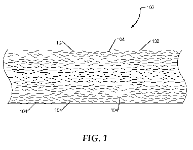
FIG. 1 is a schematic view of an embodiment of a composite material;
FIG. 2 is an isometric view of an embodiment of a sealing component having
a composite material; and
FIG. 3 is a sectional side view of a system having a sealing component with a
composite material.
The use of the same reference symbols in different drawings indicates similar
or identical items.
- 3 -
CA 02823060 2013-06-25
WO 2012/092200
PCT/US2011/067198
DETAILED DESCRIPTION OF THE PREFERRED EMBODIMENT(S)
In an embodiment, an EMI/RFI sealing component can reduce electromagnetic
noise caused by radio frequency interference passing through a gap in an
enclosure.
The EMI/RFI gasket can include a composite material comprising a polymer and a
metal fiber filler dispersed within the polymer.
FIG. 1 shows an exemplary composite material 100. The composite material
100 includes a polymer 102 and a filler 104. In an embodiment, the polymer 102
can
include a thermoplastic material, such as an engineering or high performance
thermoplastic polymer. For example, the thermoplastic material may include a
polyketone, a polyaramid, a thermoplastic polyimide, a polyetherimide, a
polyphenylene sulfide, a polyethersulfone, a polysulfone, a polyphenylene
sulfone, a
polyamideimide, an ultra high molecular weight polyethylene, a thermoplastic
fluoropolymer, a polyamide, a polybenzimidazole, a liquid crystal polymer, or
any
combination thereof.
In a particular embodiment, the thermoplastic material can be a thermoplastic
fluoropolymer, a polyethylene, and a polyketone. The polyketone can include a
polyether ether ketone (PEEK), a polyether ketone (PEK), a polyether ketone
ketone
(PEKK), a polyaryl ether ketone (PAEK), polyether ketone ether ketone ketone,
a
derivative thereof, or a combination thereof. An exemplary thermoplastic
fluoropolymer includes fluorinated ethylene propylene (FEP),
polytetrafluoroethylene
(PTFE), a terpolymer of tetrafluoroethylene, hexafluoropropylene, and
vinylidene
fluoride (THY), polychlorotrifluoroethylene (PCTFE), ethylene
tetrafluoroethylene
copolymer (ETFE), ethylene chlorotrifluoroethylene copolymer (ECTFE), or any
combination thereof. Examples of polyethylene may include a high density
polyethylene (HDPE), a high molecular weight polyethylene (HMWPE), an ultra
high
molecular weight polyethylene (UHMWPE), a cross-linked polyethylene (PEX), a
high density cross-linked polyethylene (HDXLPE), or combinations thereof.
Other
thermoplastic resins may include polyvinylidene fluoride (PVDF),
perfluoroalkoxy
(PFA) or combinations thereof.
- 4 -
CA 02823060 2013-06-25
WO 2012/092200
PCT/US2011/067198
In addition, thermosets may be used in place of the thermoplastics.
Thermosets may include polymers such as polyimide, polyester, etc., or
combinations
thereof.
In an embodiment, the filler 104 can include a metallic fiber, particle or
powder. For example, some embodiments of filler 104 include nickel particles
or
powder. Other embodiments comprise silver-coated tin. Alternatively, the
metallic
fiber may comprise stainless steel fiber, bronze fiber, aluminum fiber, nickel
fiber, or
any combination thereof. The metallic fiber can have a length in a range of
about 2
mm to about 20 mm, such as in a range of about 3 mm to about 10 mm, even in a
range of between about 4 mm and about 8 mm. Further, the metallic fiber can
have a
diameter in a range of about 1 micron to about 25 microns, such as in a range
of about
3 micron to about 15 microns, even in a range of about 5 micron to about 10
microns.
In some embodiments, the filler may comprise about 40% to about 60%, by
weight, of
the composite material.
In an exemplary embodiment, the composite material can include at least
about 15.0wt% metal fiber filler. For example, the composite material may
include at
least about 20.0wt% metal fiber filler, such as at least about 25.0wt% metal
fiber
filler, at least about 30.0wt%, or even at least about 35.0wt% of the metal
fiber filler.
The metal fibers can increase the ability of current to pass through the
composite material and can reduce the resistivity of the composite material.
In an
embodiment, the composite material can have a volume resistivity of not
greater than
about 10 Ohm-cm, not greater than about 5 Ohm-cm, not greater than about 1 Ohm-
cm, not greater than about 0.5 Ohm-cm, such as not greater than about 0.1 Ohm-
cm,
such as not greater than about 0.05 Ohm-cm, even not greater than about 0.01
Ohm-
cm. In a particular embodiment, the volumetric resistivity can be at least
about
0.00001 Ohm-cm.
In a further embodiment, the composite material can include additional
conductive fillers, such as metals and metal alloys, conductive carbonaceous
materials, ceramics such as borides and carbides, or any combination thereof.
These
materials may be fibers or particulates in form.
- 5 -
CA 02823060 2013-06-25
WO 2012/092200
PCT/US2011/067198
In an example, metals and metal alloys can include bronze, aluminum, gold,
nickel, silver, alloys thereof, or any combination thereof. Examples of
conductive
carbonaceous materials include carbon fibers, sized carbon fibers, PAN carbon
fibers,
carbon nanotubes, carbon nanofibers, carbon black, graphite, extruded
graphite, and
the like.
Additionally, the conductive carbonaceous materials can include carbon fibers
and polymer fibers coated with vapor deposited metals, such as silver, nickel,
and the
like. Examples of ceramics can include borides and carbides. Additionally, the
ceramics can be coated or doped ceramics. In a particular embodiment, the
conductive filler can be finely dispersed within the composite material.
Conductive
fillers can be employed to increase the conductivity of the composite
material.
In an exemplary embodiment, the composite material can include a total
amount of conductive fillers (metal fiber filler and additional conductive
fillers) of at
least about 20.0wt%. For example, the composite material may include a total
amount of conductive fillers of at least about 30.0wt%, such as at least about
40.0wt%, at least about 50.0wt%, at least about 60.0wt%, or even at least
about
70.0wt%. However, too much resistivity modifier may adversely influence
physical
or mechanical properties. As such, the total amount of conductive fillers may
not be
greater than about 95.0wt%, such as not greater than about 90.0wt%, or not
greater
than about 85.0wt%. In another example, the composite material may include not
greater than about 75.0wt% total conductive filler. In a particular example,
the
composite material includes a total amount of conductive filler in a range of
about
40.0wt% to about 75.0wt%, such as a range of about 50.0wt% to about 75.0wt%,
or
even about 60.0wt% to about 75.0wt%.
Additionally, the composite material can include other additives to impart
particular properties to the polymer, such as, for example, pigments,
biocides, flame
retardants, antioxidants, and the like. Exemplary pigments include organic and
inorganic pigments.
In some embodiments, the composite material can be substantially free of non-
conductive silica fillers that may reduce conductivity between the metal fiber
fillers
and the other conductive fillers. Examples of silica fillers can include
silica,
- 6 -
CA 02823060 2013-06-25
WO 2012/092200
PCT/US2011/067198
precipitated silica, alumina silicates, thermal silica, also called pyrogenic
silica, and
non-pyrogenic silica. Silica may be used in small amounts to improve
dispersion of
materials that are difficult to blend.
In a particular embodiment, the composite material can have a relatively low
coefficient of friction. For example, the coefficient of friction of the
composite
material can be not greater than about 0.4, such as not greater than about
0.2, even not
greater than about 0.15.
In an embodiment, the composite material can be a relatively stiff material. A
Young's modulus can be a measure of the stiffness of the composite material
and can
be determined from the slope of a stress-strain curve during a tensile test on
a sample
of the material. The composite material can have a Young's modulus of from
about 5
ksi to over 2000 ksi. Generally, the composite material can have a Young's
modulus
of about 12 ksi to about 900 ksi.
In an embodiment, the composite material can be resistant to deformation.
Deformation under load can be a measure of the resistance to deformation of
the
composite material and can be determined according to ASTM D-621 by applying a
load to a sample of the composite material for 2000 hours and measuring the
loss in
height of the sample. The composite material can have a deformation under load
of
within a range of about 3% to about 15%.
FIG. 2 shows an exemplary sealing component 200 according to an aspect of
the present disclosure. The seal component 200 may comprise a seal, a gasket,
a
back-up ring, etc., and perform as a structural support component for a
sealing device
or system. For example, seal component 200 may include a ring 202 with an
outside
surface 204 and an inside surface 206 defining an opening 208 through the
ring.
The gasket 200 can be used in an electronic system to reduce EMI/RFI and
provide a chemical resistant environmental seal. In a particular embodiment,
the
gasket 200 can be placed between two parts of an electronics enclosure, such
as
between a body and a lid. In another particular embodiment, the gasket 200
having a
low coefficient of friction can be used between a static component and a
rotary
component.
- 7 -
CA 02823060 2013-06-25
WO 2012/092200
PCT/US2011/067198
FIG. 3 illustrates an exemplary system 300. System 300 can include a static
component 302 and a rotating component 304. The rotating component 304 can
rotate relative to the static component 302. The system 300 can further
include a
sealing component 306, such as an annular seal, placed between the static
component
302 and the rotating component 304. The sealing component 306 can be similar
to
sealing component 200. In an embodiment, the sealing component 306 can act to
prevent environmental contamination, such as by dust, water, chemicals, gases,
or the
like, from entering into or exiting the system through the gap between the
static
component 302 and the rotating component 304. Additionally, the sealing
component
306 can act to reduce EMI/RFI from affecting the system or emanating from the
system.
Turning to the method of making the composite material, the metal fibers can
be combined with a polymer material to form a blended powder. In a particular
embodiment, the polymer material can be a thermopolymer, such as a polyketone,
a
polyethylene, or a thermoplastic fluoropolymer. The thermopolymer can be added
in
a powder or pellet form and can be mixed with the metal fibers, such as by
blending,
for example in a Brabender mixer or a Patterson Kelley blender, or milling,
such as by
dry milling, for example in a hammer mill. The presence of the fibers, such as
stainless steel fibers, can make or render the thermoplastic material,
composite
material, seal component, or system non-extrudable.
The blended powder can be formed in a desired shape, such as by pressing
into a mold. In this process the mold temperature may be ambient or elevated
up to a
particular melt temperature as necessary. Additionally, the blended powder can
be
sintered, either within the mold or can be heated or otherwise bonded together
to form
a green body that can be removed from the mold prior to sintering. Further,
the
composite material may be machined after shaping to form the seal body, or
skived to
produce sheet.
In a particular embodiment, the blended powder can be compressed into the
mold and sintered. After sintering, the mold can be removed from the sintering
oven
and subjected to additional compression while the composite material remains
at an
elevated temperature. After cooling, the composite material can be machined to
remove excess material and produce a final desired shape, such as a gasket or
seal.
- 8 -
CA 02823060 2013-06-25
WO 2012/092200
PCT/US2011/067198
EXAMPLES
Samples are tested according to ASTM D 991, ASTM D 4496, or Mil DTL
83528-C to determine volume resistivity. The results are provided in Table 1.
Comparative Sample 1 is Fluoralloy A56 (commercially available from Saint-
Gobain) and includes PTFE and a carbon filler.
Sample 1 is prepared by blending a metal fiber filler (35wt%), carbon filler
(5wt%), and PTFE (60wt%). The metal fiber filler is blended in a Patterson
Kelley
Blender to separate the metal fibers. Carbon filler and PTFE are added to the
metal
fiber filler and blended together with the Patterson Kelley Blender. The
resulting
blended powder is compression molded and sintered to form Sample 1.
Table 1
Volume Deformation Young's
Resistivity (Ohm- Under Load (%) Modulus
cm)
Comparative 4.15 10 120 ¨
150
Sample 1 ksi
Sample 1 0.13 14 185 ksi
minimum
Note that not all of the activities described above in the general description
or
the examples are required, that a portion of a specific activity may not be
required,
and that one or more further activities may be performed in addition to those
described. Still further, the orders in which activities are listed are not
necessarily the
order in which they are performed.
In the foregoing specification, the concepts have been described with
reference to specific embodiments. However, one of ordinary skill in the art
appreciates that various modifications and changes can be made without
departing
from the scope of the invention as set forth in the claims below. Accordingly,
the
specification and figures are to be regarded in an illustrative rather than a
restrictive
sense, and all such modifications are intended to be included within the scope
of
invention.
- 9 -
CA 02823060 2013-06-25
WO 2012/092200
PCT/US2011/067198
As used herein, the terms "comprises," "comprising," "includes," "including,"
"has," "having" or any other variation thereof, are intended to cover a non-
exclusive
inclusion. For example, a process, method, article, or apparatus that
comprises a list
of features is not necessarily limited only to those features but may include
other
features not expressly listed or inherent to such process, method, article, or
apparatus.
Further, unless expressly stated to the contrary, "or" refers to an inclusive-
or and not
to an exclusive-or. For example, a condition A or B is satisfied by any one of
the
following: A is true (or present) and B is false (or not present), A is false
(or not
present) and B is true (or present), and both A and B are true (or present).
Also, the use of "a" or "an" are employed to describe elements and
components described herein. This is done merely for convenience and to give a
general sense of the scope of the invention. This description should be read
to include
one or at least one and the singular also includes the plural unless it is
obvious that it
is meant otherwise.
Benefits, other advantages, and solutions to problems have been described
above with regard to specific embodiments. However, the benefits, advantages,
solutions to problems, and any feature(s) that may cause any benefit,
advantage, or
solution to occur or become more pronounced are not to be construed as a
critical,
required, or essential feature of any or all the claims.
After reading the specification, skilled artisans will appreciate that certain
features are, for clarity, described herein in the context of separate
embodiments, may
also be provided in combination in a single embodiment. Conversely, various
features that are, for brevity, described in the context of a single
embodiment, may
also be provided separately or in any subcombination. Further, references to
values
stated in ranges include each and every value within that range.
- 10-