Note: Descriptions are shown in the official language in which they were submitted.
CA 02823109 2013-06-26
1
METHOD OF MODERNISING A LIFT INSTALLATION
The invention relates to a method of modernising a lift installation according
to the
preamble of claim 1. In addition, the invention relates to the use of an input
device for the
lift installation which is to be modernised by this method and is modernised
as well as to a
computer program product for operating and modernising a lift installation.
Lift installations for conveying persons and goods have been known for a long
time and are customary. Since lift installations are relatively long-term
capital-cost items
with service lives of 20 years and more it can happen that with time these no
longer
satisfy changing demands. In certain circumstances modernisation of the
installation is
then required. By the term "modernisation" there is to be understood in the
following not
just exchange of technologically aged components. Modernisation particularly
also
means rebuilding or redesigning existing installations and thus adapting these
to new
needs. Through modernisation, lift installations can, for example, be operated
more
safely, more efficiently, more comfortably for users and/or more favourably
for operators.
In lift installations of older mode of construction the storeys are selected
by
pressing touch buttons of an input device arranged in a lift cage. Increasing
popularity is
enjoyed by lift installations with storey terminals which are arranged on
storeys and by
way of which destination calls can be input from outside the cage, whereby the
installations can be operated more efficiently.
A method for modernisation of a lift installation already equipped with storey
terminals is described in EP 1 900 672 B1. The control functions of the lift
installation can
be updated by means of the modernisation. For that purpose, use is made of a
mobile
apparatus by which a near-field radio connection for communication of control
data can
be established. In practice, it has proved that planners and building owners
frequently
prefer, at least for an initial phase, conventional installations of older
mode of construction
in which lift users can select the desired storeys by way of input devices at
the cage side.
A further modernisation method for lift installations has become known from EP
1
935 824 Al . The lift installation to be modernised comprises several lifts
arranged
adjacent to one another. Terminals for input of destination storey calls are
located on the
storeys. The method is, summarised briefly, distinguished by the fact that new
storey
CA 02823109 2013-06-26
=
2
terminals are installed on the storeys and these are respectively incorporated
in an
already existing group control.
It is accordingly an object of the present invention to avoid the
disadvantages of
the prior art and, in particular, to create a method for modernisation of lift
installations of
the kind stated in the introduction, by which or through which a lift
installation can be
created with which a user of the lift can be conveyed in simple and efficient
manner to the
desired storey. Moreover, the method shall be economic and shall with small
outlay
satisfy current demands with respect to destination call control.
According to the invention this and other objects are fulfilled by a method
having
the features in claim 1. In the modernisation a storey terminal for input of
the destination
storey is installed on at least one storey of the building. This storey
terminal is so coupled
(directly or indirectly) to the control device connected with the input device
of the cage
side that at least in the standard mode after input of the destination storey
call detected
by means of the storey terminal the cage automatically travels to the selected
destination
storey, wherein at the same time a storey selection in the cage is no longer
possible by
use of the input device. With the afore-mentioned indirect coupling it is
possible in the
modernisation to integrate in a control system, which includes the control
device, a further
control device. Through the addition of the storey terminal to the existing
installation and
the electronic coupling of the storey terminal the at least one lift can be
operated by an
advantageous destination call control. Due to the fact that in the standard
mode after
storey selection with use of the storey terminal is excluded or blocked by way
of the input
device at least under certain preconditions, unplanned stops of the cage can
be
prevented and thus the lift installation operated more efficiently. The input
device at the
cage side remains in place and can be further used.
The input device having activatable indicating means for representation of
selected storeys is further adapted in such a manner in the modernisation of
the control
device that the indicating means after input of the storey call by way of the
storey terminal
are activated. The mentioned indicating means can in that case be, for
example, letters,
numbers, drawings or figures illustrated on a touchscreen surface. Activated
indicating
means can, for example, be lit up more brightly or in another colour. The user
thus sees
in the cage which storey he or she has selected beforehand at the storey
terminal and to
which destination the lift will now convey him or her.
CA 02823109 2013-06-26
3
The already existing input device can comprise a touchscreen surface with
input buttons preferably of capacitive design, wherein prior to the
modernisation they
react to button contacts and thus enable input of the desired storey by the
user. In the
modernisation the control device can be adapted in such a manner that at least
in a
standard mode the touchscreen function, which reacts to contact, of the input
buttons for
storey selection is deactivated. Apart from the capacitive system, resistive,
inductive or
other contact- sensitive systems are also conceivable.
In a preferred form of embodiment the control device can in the modernisation
be
so set by, for example, adaptation of the control program that the buttons at
least
associated with the storey selection, or the region of the touchscreen surface
associated
with the storey selection, of the input device serves after the modernisation
substantially
only for information purposes.
The input device can have, apart from buttons for storey selection, further
special
input buttons. These special input buttons can be provided for, for example,
issue of an
alarm in emergency situations, emergency opening or possibly for ensuring a
longer time
of opening for disembarking of handicapped users. The system containing storey
terminal, input device and control device can be adapted in such a manner in
the
modernisation that after the modernisation the mentioned special input buttons
are
operable in an operating mode in which the special input buttons - by contrast
to the input
buttons for the storey selection - remain activatable.
If the input device comprises a card reader and/or a handicapped person's
button
it can be advantageous if in the modernisation the control device is adapted
in such a
manner that after reading of an authorised card or in the case of button
pressure on or
button contact with the handicapped person's button the deactivated input
buttons are
freed for renewed input for an activation. In this manner an efficient and
nevertheless
flexible mode of operation for the lift can be ensured after the
modernisation.
A further aspect of the invention relates to the use of an input device of the
cage
side which preferably comprises a touchscreen surface with input buttons
preferably of
capacitive design, wherein the input device is distinguished by the fact that
it can be used
unchanged in a lift installation before and after modernisation. Before
modernisation, the
user has to input the desired storey by way of input buttons rather than input
means.
After the modernisation the input device serves with respect to the input
means
CA 02823109 2013-06-26
4
concerning storeys only for information purposes. After the storey selection,
i.e.
after input of the destination storey call detected by means of the storey
terminal, a storey
selection in the cage is no longer possible by users of the input device.
Finally, a further aspect of the invention relates to a computer program
product for
operating and modernisation of the afore-described installation.
Further individual features and advantages of the invention are evident from
the
following description of an exemplifying embodiment and from the drawings, in
which:
Figure 1 shows a simplified illustration of an existing installation
or an
installation to be modernised.
Figure 2 shows the lift installation after modernisation and
Figure 3 shows a further variant of the lift installation after the
modernisation.
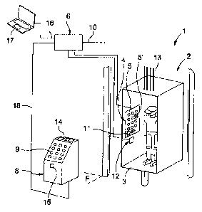
Figure 1 shows a lift installation, which is denoted overall by 1, with a lift
2, which
has a cage movable in a vertical shaft. Depending on the size of the building
and the
building purpose the lift installation can also comprise several lifts
arranged adjacent to
one another, which can be designed to be the same as or similar to that in
Figure 1. Also
not illustrated are the further storeys disposed above and below with respect
to the storey
plane F.
A cage 3 of the lift installation is, for example, fastened to several support
cables
13 and movable upwardly and downwardly by way of drive means known in
themselves
to the expert. The following modernisation method still to be described in
more detail is,
however, also suitable for other lift types. In particular, instead of support
cables also
other support means such as individual or multiple support belts of different
materials and
compositions such as synthetic materials, metals or other materials come into
question.
The modernisation method would also be conceivable for hydraulically operated
lifts.
A line by way of which the drive means (not illustrated) are activatable is
indicated
by 10. The lift installation according to Figure 1 contains on each storey of
the building an
input device 7 which is mounted on a vertical wall and disposed near the lift
shaft and by
CA 02823109 2013-06-26
way of which a user can call the cage to his or her storey. Input devices of
that kind at
the storey side are also located in the storeys lying above and below. An
input device,
which is denoted by 4, is arranged at an inner side of a cage wall of the lift
cage 3. The
input device 4 has input buttons 5 by way of which the user can input his or
her
destination storey. Apart from these destination storey input buttons 5 the
input device 4
has further buttons 11 for special purposes. These buttons 11 serve for, for
example,
issue of an alarm, emergency opening or as a so-called handicapped person's
button.
The storey terminal 8 has, for example, a touchscreen surface on which the
input buttons
9 and 11 are arranged.
The control device denoted by 6 is electronically connected by way of
conductors,
which are indicated by lines, with the input device 4 at the cage side, the
cage call input
device 2 and by way of the conductor 10 with the drive for the lift 2. The
device at the
cage side comprises a touchscreen surface, the input buttons 5 and 11 of which
are
designed as capacitive touch-sensitive buttons. The input device 4 is designed
in such a
manner that, for example, at the time of or after selection of a storey the
corresponding
button after contact by the user lights up. The control device 6 comprises
memory means
(not illustrated) on which data and a computer program for operating the lift
installation 1
are stored. The control device 6 has an interface 16 by way of which
communication with
the control system can be produced and further data can be supplied to the
memory
means of the control device 6.
The demands imposed on a lift installation can change in the course of time.
Starting from the existing installation according to Figure 1 the lift
installation can be
modified in such a manner by the modernisation method according to the
invention that
the lift installation can thereafter be operated efficiently and keeping with
times. In the
modernisation, storey terminals are installed on the storeys of the building,
which
terminals are connected with the control device 6 by way of data lines 18
(Fig. 2). The
storey terminals 8 can, as evident from the exemplifying embodiment according
to Figure
2, be designed as column-like column bodies protruding relative to the floor
of the storey
plane F. The storey terminal 8 has, by way of example, an inclined surface on
which
input buttons 9 for each storey are arranged. Indicating means 14 for
allocation of the lift
to the user are arranged on a horizontal surface. Other shapes and modes of
construction for storey terminals are obviously also conceivable. As evident
from Figure
2, in the course of the modernisation the input devices located on the storeys
near the
shaft are removed (see Fig. 1: input device 7). However, it would be obviously
also be
CA 02823109 2013-06-26
6
conceivable to leave the installed input device (7; Fig. 1) in place and
merely
deactivate the corresponding buttons of the mentioned input device by
adaptation of
control system. Alternative storey terminals could comprise touchscreens
fastened to
building inner walls. For example, at each storey a flat storey terminal could
replace the
simple cage call input device or be arranged in place thereof on the wall.
In the modernisation, a technician produces a connection with the control
system
by way of the interface 16 and in that case introduces a new computer program
product
or an update for the existing computer program product into the system,
whereby after
the modernisation the lift installation can be operated in the previously
described mode
and manner. The computer program product or the update thereof is stored in an
electronic data processing unit. This data processing unit can be a component
of the
control device 6. However, it would also be conceivable to arrange the data
processing
unit at the input device 4 at the cage side.
A technician can now perform the upgrade of the lift installation and
reconfigure
the control in simple mode and manner by a laptop 17 or another apparatus. A
corresponding data packet for the update or the reconfiguration of the control
can be filed
on a memory element (for example a memory card). Moreover, it would also be
conceivable to design, by means of portable wireless transmitters or by way of
a near-
field radio connection, for prevention of improper interventions in the
control system. The
coupling can be effected by way of data cable or also in wire-free manner. The
interface
can then also be designed in such a manner that a technician can access and
intervene
on or in the control system from a remote location in that he or she, for
example,
executes a so-called 'remote' by way of the Ethernet. In this manner, the
modernisation
can be performed very rapidly. Through the reuse of the existing touchscreen
of the input
device 4 it is ensured that - with the exception of the storey terminal to be
installed - no
high investment costs in the lift installation are needed.
After modernisation has been carried out, the mode of operation of the lift
installation 1 in the standard mode is as follows: After the user has selected
the
destination storey, which is designed by him or her, on the storey terminal 8
with use of
the buttons 9 a lift is allocated to him or her by the display 14 (Fig. 2). In
the cage 3 of the
lift 2 allocated to him or her the touchscreen surface of the input device 4
shows the
storey previously selected by him or her. This can be effected, for example,
by lighting up
the input button provided with a number for a storey. An input button lit up
in that manner
CA 02823109 2013-06-26
=
7
is indicated in Figure 2 by 5'. A card reader 12 is disposed below the
touchscreen
surface of the input device 4. The card reader can obviously also be
integrated in the
input device 4.
Other locations for the card reader are also conceivable. Thus, the card
reader
could comprise, for example, a sensor or a receiver arranged behind the same
glass
pane for the touchscreen surface of the input device 4. The storey terminals
do not
necessarily have to comprise touchscreen surfaces; tactile pushbuttons or
other input
variants, for example, also come into question. The storey selection can
additionally or
alternatively be effected for input via the buttons 9 also through an
identification of the
user. For this purpose the storey terminal 8 can comprise a card reader 15 or
other
identification unit. After identification of an authorised user, for example
by means of an
ID card, the control system recognises to which destination storey the user
would like to
travel. =
The region, which is associated with the storey selection, of the touchscreen
surface of the input device with the input buttons 5 serves, after the
modernisation, only
for information purposes. The input device 4 receives, triggered by the storey
selection at
the storey terminal 8, an activation signal from the control device.
Thereafter, the
indicating means associated with the selected storey are activated for
representation of
the storey. Indicating means activated in that manner can comprise lighting
up. Insofar
as the remaining indicating means at least in the operating phase permanently
light up, it
can be advantageous if the activated indicating means lights up more brightly
and/or in
another colour. The indicating means can be designed as components separate
from the
input buttons. The indicating means are preferably designed as an integrated
component
of the input buttons. A button indicating a storey in this manner by lighting
up is indicated
in Figure 2 by way of example as a button denoted by 5'. In addition, after
the
modernisation, usual specific input buttons should remain activatable. The
buttons
serving for special purposes such as issue of an alarm, emergency opening or
the like
are denoted in Figures 1 and 2 by 11.
The modernised control system, however, also permits departures from the
standard mode for specific cases: Thus, the control system can optionally be
adapted in
such a manner that after reading of an authorised card and/or in the case of
button
pressure on or button contact with a handicapped person's button 11 the
deactivated
input buttons 5 are freed for renewed input for activation.
CA 02823109 2013-06-26
8
Depending on how the hardware of the original control device was designed, it
can be necessary in the modernisation to undertake control engineering
adaptations of
the control system so as to enable the new functionality. In cases of that
kind, as evident
from Figure 3, an additional control device 19 or a further control module is
integrated in
the control system. As far as the newly added control device 19, the lift
installation 1
corresponds with the installation of Figure 2. In Figure 3 the control device
19 is, by way
of example, constructed as a separate subassembly disposed in operative
connection
with the first control device 6. The control device 19 can already be pre-
configured,
whereby the lift installation is quickly ready for reuse. Moreover, it is also
conceivable to
configure the control or if required also undertake an update or a
reconfiguration of the
control software by way of means (not illustrated here) such as, for example,
a laptop
connected by way of an appropriate interface, by way of a near-field radio
connection or
by way of an Ethernet remote.