Note: Descriptions are shown in the official language in which they were submitted.
CA 02823296 2013-08-08
0
NONDESTRUCTIVE EXAMINATION OF STRUCTURES HAVING
EMBEDDED PARTICLES
BACKGROUND
Nondestructive examination (NDE) may be used to evaluate properties of
composite
structures. For instance, NDE such as ultrasonic testing may reveal internal
structural inconsistencies such as voids, wrinkles, cracks and delanninations.
However, ultrasonic testing does not reveal internal strains within composite
structures. Other techniques may determine strains at the surface or bulk of
composite structures, but not within the composite structures.
It would be desirable to nondestructively determine strains within composite
structures.
SUMMARY
According to an embodiment herein, a system comprises a structure having
particles
embedded at a level within the structure, and X-ray imaging apparatus for
capturing
images of the particles at the level.
According to another embodiment herein, a method of performing nondestructive
examination on a structure having embedded particles comprises illuminating
the
structure with X-rays; forming an image of the illuminated structure, the
image
showing the particles; and determining displacements of the particles in the
image.
-1-
CA 02823296 2015-05-04
According to another embodiment herein, there is provided a system comprising:
a
structure having particles embedded at a plurality of different levels within
the
structure, wherein at least some of the particles at each of the plurality of
different
levels are of a different type than the particles at each other one of the
plurality of
different levels; and an X-ray imaging apparatus for capturing images of the
particles
at the plurality of different levels.
According to another embodiment herein, there is provided a method of
performing
nondestructive examination on a structure having embedded particles, the
particles
embedded at a plurality of different levels within the structure, the method
comprising:
illuminating the structure with X-rays; forming an image of the illuminated
structure,
the image showing the particles; and determining displacements of the
particles in the
image; wherein at least some of the particles at each of the plurality of
different levels
are of a different type than the particles at each other one of the plurality
of different
levels.
-1a-
CA 02823296 2013-08-08
According to another embodiment herein, a laminate comprises a plurality of
plies of
reinforcing fibers in a matrix. The matrix contains patterns of metal
particles
embedded within different plies, wherein the particles embedded in the
different plies
differ by at least one of nominal size and composition.
These features and functions may be achieved independently in various
embodiments or may be combined in other embodiments. Further details of the
embodiments can be seen with reference to the following description and
drawings.
BRIEF DESCRIPTION OF THE DRAWINGS
FIG. 1 is an illustration of a structure including embedded particles.
FIGS. 2A and 2B are illustrations of particles embedded within a structure
before and
after the structure has undergone stress.
FIG. 3 is an illustration of a method of determining strain within a structure
having
embedded particles.
FIG. 4 is an illustration of a system for determining strain within a
structure having
embedded particles.
FIG. 5 is an illustration of a method of using the system of FIG. 4.
FIG. 6 is an illustration of a multi-ply structure including embedded
particles at
multiple levels.
-2-
CA 02823296 2013-08-08
FIG.7 is an illustration of a method of fabricating and nondestructively
examining a
CFRP laminate.
DETAILED DESCRIPTION
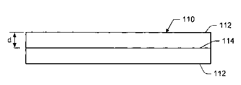
Reference is made to FIG. 1, which illustrates a structure 110 including
embedded
particles. In some embodiments, the structure 110 may be a composite laminate
composed of a plurality of plies of reinforcing fibers embedded in a matrix.
For
instance, the laminate may include multiple plies of carbon reinforcing fibers
embedded in a plastic matrix. In FIG. 1, each element 112 represents multiple
plies.
In other embodiments, the structure 110 may include two or more members 112
(e.g., rigid composite members) that are adhesively bonded together at a bond
line.
The particles are embedded at a level 114 below a surface of the structure
110. As
shown in FIG. 1, the level 114 is at a depth (d) below the surface. For a
structure
110 including members 112 adhesively bonded together at a bond line, the
particles
may be embedded in the bond line. That is, the bond line is at a depth (d)
below the
surface. For a structure 110 including a plurality of laminated plies 112, the
particles
may be embedded in one or more of the plies. That is, the ply or plies
containing the
embedded particles are a depth (d) below the surface.
The embedded particles are made of a material that is not completely
transparent to
X-rays. For instance, the embedded particles may fluoresce, scatter or absorb
X-
rays. In some embodiments, the particles may be metal particles. The particles
may
be micron-sized or smaller.
Reference is now made to FIG. 2A, which shows a plurality of embedded
particles
210. The particles 210 are arranged in a pattern that is non-uniform and
irregular. In
some embodiments, the particles 210 may be arranged in clumps. In other
-3-
CA 02823296 2013-08-08
embodiments, the particles 210 may be arranged in a stochastic pattern. For
example, the particles 210 may be arranged in a stochastic speckle pattern.
The structure 110 may undergo stress from external forces and/or internal
forces
(e.g., by temperature cycling). The stress causes strain in the structure 110.
In
laminates made of composite fiber reinforced plastic (CFRP), for instance, the
strain
may cause deformations or internal inconsistencies such as voids, wrinkles,
cracks
and delaminations.
Reference is now made to FIG. 3, which illustrates a method of determining
strains
within a structure having particles embedded particles therein, where the
particles
are not completely transparent to X-rays. At block 310, the structure is
illuminated
with X-rays. Except for the particles, the structure may fully transmit the X-
rays. The
particles prevent the X-rays from being fully transmitted. For instance, the
particles
may fluoresce, scatter or absorb the X-rays, or they may reflect the X-rays
(e.g., at
grazing incidence).
At block 320, an image of the illuminated structure is formed. The image shows
a
pattern of particles at a level within the structure.
At block 330, the image is processed to determine displacements of the
particles at
different locations at the level. At block 340, strains are computed from the
displacements.
Reference is made to FIGS. 2A and 2B, which illustrate particles 210 embedded
at a
level within the structure 110. Assume FIG. 2A is a baseline image of the
particles
210 prior to the structure 110 undergoing stress, and assume FIG. 2B is an
image of
the particles after the structure 110 has undergone stress. A pixel block 220
encompasses several particles 210. Notice the skewing of the pixel block 220
in
-4-
CA 02823296 2013-08-08
FIG. 2B. The skewing indicates that the particles 210 within the pixel block
220 have
been displaced as a result of the stress.
Displacements and strains may be computed by digital image correlation (DIC).
DIC
is an optical method that employs tracking and image registration techniques
for
accurate measurements of changes in images. DIC may perform pattern
recognition
on multiple images. Each image may be broken up into blocks of pixels (e.g.,
15x15
pixel blocks, 25x25 pixel blocks 15x20 pixel blocks) that cover a certain
number (e.g.,
five to seven) particles. These blocks of pixels are found in all of the
images, and
then the shape of each pixel block in each image is determined. The change of
shape of each block of pixels determines a displacement at a location at the
level. In
this manner, displacements are determined at different locations at the level.
A set of strains may then be computed at each block center. A strain field for
the
level may be formulated as a matrix of the strains. Interior modulus
properties may
also be determined from stress versus strain curves in the elastic region of
the
material.
Reference is now made to FIG. 4, which illustrates a system 410 for
determining
strains at a level within a structure 110, where particles are embedded at
that level.
The system 410 includes imaging apparatus 420 for capturing images of the
particles
within the structure 110. The imaging apparatus 420 of FIG. 4 includes first
and
second X-ray sources 422 and first and second X-ray detectors 424. The sources
422 may provide collimated X-rays. If the particles block the X-rays, the
detectors
may include semiconductor detectors that convert X-rays to electrical signals
or
semiconductor detectors that convert X-rays to visible light, which is then
converted
to electric signals. If the particles fluoresce in response to the X-rays, the
image may
be formed by energy dispersive detection.
-5-
CA 02823296 2013-08-08
High contrast in the images is desirable. Distances between the sources 422,
the
structure 110, and the detectors 424 may be adjusted to give the proper field
of view
and best contrast.
The first and second detectors 424 may be oriented at an angle with respect to
the
particles to create depth perception in the images. Depth perception, in turn,
enables
structural inconsistencies such as internal delaminations to be identified.
A system herein is not limited to two detectors. Some embodiments may include
only a single detector. Others may include more than two detectors.
The system 410 further includes a computer 430 programmed to process the
images
created by the detectors 424. The processing includes digital image
correlation of
the pixel blocks of particles within the images. The computer 430 may be
programmed with a commercial off the shelf DIC software, such as ARAMIS
software.
In some embodiments, the computer 430 may be further programmed to identify
internal structural inconsistencies from the strain field. For example, the
strain field
may be compared to baseline data corresponding to different types of
structural
inconsistencies. In other embodiments, skilled technicians may analyze the
strain
field to identify structural inconsistencies.
FIG. 5 is an illustration of a method of using the system of FIG. 4 to perform
nondestructive inspection on a structure having particles embedded at a level.
At
block 510, the computer 430 accesses a baseline image of the structure. The
baseline image represents a "healthy" structure. The baseline image may be
been
taken before the structure was placed into service, or it may be taken at a
later time
after having been stressed.
-6-
CA 02823296 2013-08-08
At block 520, the computer 430 commands the imaging apparatus 420 to capture
one or more images of the particles within the structure 110. At block 530,
the
computer 430 processes the captured and baseline images to detect displacement
of
a number of pixel blocks at each level. Several pixel blocks may be used to
determine the value of displacement at a given location.
At block 540, the computer 430 determines strains from the pixel block
displacements, and formulates a strain field at the level. If the structure
110 includes
two parts bonded together at a bond line, and the particles are embedded in
the bond
line, then a strain field would be determined at the level of the bond line.
If the
structure 110 is a laminate, and one of the plies is embedded with particles,
then a
strain field would be determined at the level of that ply.
At block 550, the strain field is used to identify internal structural
inconsistencies such
as voids, wrinkles, delaminations and cracks. For example, a delamination
would
manifest as a change in out of plane displacement (in a 3D image), while a
crack or
wrinkle would manifest as a large localized strain.
A structure herein is not limited to particles at a single level. In some
embodiments,
a structure may include particles embedded at multiple levels.
FIG. 6 is an illustration of a laminate 610 including metal particles embedded
at
multiple levels. Different types of particles are embedded in different plies.
The type
of particle may differ by nominal size and/or composition. As but one example,
one
ply 612 may be embedded with copper particles, another ply 614 may be embedded
with titanium particles, another ply 616 with aluminum particles, and so on.
Other
metals include, but are not limited to, gold, silver, tungsten, and iron.
Other plies 618
of the structure do not contain particles that affect the X-rays.
-7-
CA 02823296 2013-08-08
FIG. 6 shows every other layer being imbedded with metal particles. In
practice
however, there may be greater separation between plies having embedded
particles.
As but one example, in a laminate having thirty plies, one of every six plies
may
contain metal particles.
Reference is now made to FIG.7, which illustrates the fabrication and
nondestructive
examination of a CFRP laminate. Prior to layup, the different plies of the
laminate
are pre-impregnated with resins having different types of particles dispersed
therein
(block 710). Those plies not containing particles are impregnated with resin.
During
layup of the laminate (block 720), the pre-impregnated plies may be deposited
on a
forming tool.
After the layup has been cured (block 730), nondestructive examination is
performed.
During nondestructive examination, the laminate is illuminated with X-rays and
the
particles at different levels are imaged (block 740). In some embodiments, the
levels
may be illuminated sequentially at different X-ray energy levels, thereby
creating
images of different levels. In other embodiments, the different levels may be
illuminated and imaged in a single pass. Particles at different levels may be
differentiated by the amount of energy they absorb. For example, lead
particles will
absorb more energy than titanium particles and, consequently, will have a
lower
grayscale value in the image.
In other embodiments, the different particles absorb the X-rays and fluoresce
at
different frequencies. Images of the different levels may be formed by energy
dispersive detection, which would allow discrimination of the florescent
spectra of the
different particles. For example, the florescent spectra of titanium, copper,
tungsten,
and lead are dispersed at different levels.
-8-
CA 02823296 2013-08-08
-
Using DIC, the displacement of the metal particles in the image is determined
at
different locations for each of the different levels (block 750). Strain
fields are
computed for the different levels (block 760).
-9-