Note: Descriptions are shown in the official language in which they were submitted.
CA 02823762 2013-08-14
=
TITLE OF THE INVENTION
[0001] Residential Ductwork System
CROSS-REFERENCE TO RELATED APPLICATIONS
[0002] This application claims the benefit of U.S. Provisional Application
Nos.
61/683,059, 61/682,938, 61/682,856, and 61/682,956, all filed August 14, 2012
and all
of which are hereby incorporated by reference in their entireties.
STATEMENT REGARDING FEDERALLY SPONSORED RESEARCH OR
DEVELOPMENT
[0003] Not Applicable
INCORPORATION-BY-REFERENCE OF MATERIALS SUBMITTED ON A
COMPACT DISK
[0004] Not Applicable
BACKGROUND
[0005] In conveying heated or cooled air from a furnace or an air conditioner,
the air is
usually conducted to a rectangular c .ass-section main duct and thereafter
through
branch ducts that extend from the main duct. In recent years, these branch
ducts have
been formed from sealed circular cross-section sheet metal pipe. These branch
ducts
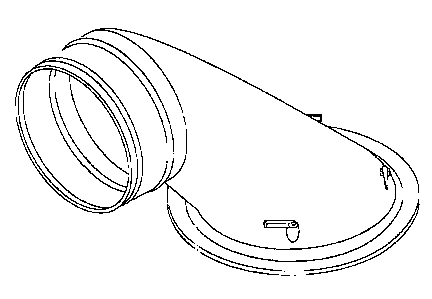
1
CA 02823762 2013-08-14
then carry the conditioned air to rehisters that open into rooms in the
building to permit
circulation of the conditioned air N; ithin the rooms.
[0006] The transition of air from the main duct to the branch duct has not
been very
efficient because the branch ducts usually extend at right angles to the main
duct
causing turbulence in the air as it transfers. Further, the type of fittings
used previously
has required extensive sealing to prevent leakage of air through the joints.
Newer
building codes now require that there be minimal leakage in the heating and
air
conditioning systems.
[0007] Traditional systems and methods of installation require the installers
to lay out
all of the ductwork and fittings and paint them so that they are all sealed.
Additionally,
there is no standard installation and the configuration of the ductwork all
depends on
the installer for residential systems
[0008] In commercial systems the ductwork is all manufactured for each
specific
building. The reason is because the cost of the building allows for custom
manufacturing and designing of HVAC systems.
[0009] The current residential structure does not include any designed HVAC
systems.
Large residential builders, such as Ryan and Moranda homes, often use a
general
floor plan for different models of homes. The floor plan and basic design will
remain
the same, but the exterior aesthetics can be altered, as well as some of the
interior
features. However, the basic home plan and rooms remain the same and those
plans are
used to build many homes.
[0010] The present invention increass both the efficiency of the flow of air
through the
system and the ease of assembly of the system, as will be seen as the
description
2
CA 02823762 2013-08-14
proceeds in conjunction with the attached drawings and the appended claims.
The
system can also reduce noise and vibration.
BRIEF SUMMARY OF THE INVENTION
[0011] The present invention is a predesigned sealed system for residential
homes. The
entire system is sealed when it leaves the manufacturer and the installer does
not have
to seal any portions of the systems. Additionally, the system can be designed
to
increase air flow, reduce energy colsumption, reduce installation time, reduce
vibration
and reduce noise.
[0012] The present invention provides for a method for creating a HVAC
ductwork
system for a residential house. A residential house plan that is to be used to
build more
than one residential house is obtainec and reviewed. A HVAC design engineer or
architect designs a HVAC ductwork system to fit that house plan, wherein the
system
optimizes the air flow throughout the house and can be reused in more than one
residential home built from the resAential house plan. The designer's or
architect's
design is reduced to a system plan :at can be delivered to a home builder and
then is
delivered to the home builder. The builder or HVAC contractor or installer
buys or
obtains manufactured ductwork calL d for in the plan and then installs the
HVAC
system in the residential house according to the system plan. The HVAC
ductwork
system can be a completely sealed sy ,,tem or self sealing as supplied from
the
manufacture so that the installer does not have to seal any items. The system
can also
increase the air flow and efficiency :ver non-sealed systems by 5, 10, or 20%.
Because
of the efficiency of the system, it is likely that flow rate of air to all of
the rooms is
3
CA 02823762 2013-08-14
within 10% of each other. The HV kC system allows for a reduction in the
installation
time of at least 10 minutes over traditional HVAC systems. Additionally, it
will allow
for the reduction of 1 man hour day.
[0013] This invention also provide3 for a method for installing a sealed
ductwork
system by providing: (1) a main duct line that is sealed during manufacturing
in order
to reduce air leakage and that will meet code requirements without the
installer having
to apply sealing material to the duct line; (2) fittings that are sealed
during
manufacturing in order to reduce air leakage and that will meet code
requirements
without the installer having to apply sealing material to the fittings; and
(3) branch
ducts that are sealed during manufacturing in order to reduce air leakage and
that will
meet code requirements without the installer having to apply sealing material
to the
branch ducts. The above described system is then installed without the
installer having
to apply any sealant. The method reduces installation time for an installer by
at least
minutes and will typically reduce one man hour day (the amount of work
produced
from one worker in one day). The method also allows for reducing the vibration
and
noise over a traditional HVAC system.
BRIEF DESCRIPTION OF THE DRAWINGS
[0014] Fig. 1 is a perspective view of the high efficiency fitting of the
present
invention.
[0015] Fig. 2 is a perspective view of a boot.
[0016] Fig. 3 is a perspective view of sealed duct.
[0017] Fig. 4 is perspective view of sealed duct system within a house.
4
CA 02823762 2013-08-14
[0018] Fig. 5 is a sectional view o a sealed longitudinal seam.
[0019] Figs. 6 and 7 are perspective views of a transverse seam.
[0020] Fig. 8 shows a high efficiency fitting attached to a main duct that is
attached to
the joists in a structure in a side elevation view.
DETAILED DESCRIPTION
[0021] Large residential home builders have basic building design models for a
variety
of homes. The homes have the sar- e basic structure and configuration, but
sometimes
contain modifications in appearance and material selection such as flooring
countertops, doors, etc. However, the basic layout and configuration remain
the same
to reduce the cost and efficiency in which the home is built.
[0022] The HVAC is installed after the homes are built. The same home design
could
end up with multiple, different, HVAC ductwork configurations and it will
depend on
the particular installer. This can lead to increases in time in installation,
as well as
inefficient air flow which increases energy consumption and cost for home
owners.
The installer in current methods ofien has to lay out parts and seal all of
the parts prior
to installation with a mastic type application. This is typically at least an
8 hour day for
one installer.
[0023] In addition, this type of installation can often lead to inefficient
air flow. It is
common for people owning a home to complain about the air flow being less or
the
temperature in one room being diffen-nt from the other rooms in the house.
This can be
created by inefficient HVAC ductwel k system design.
CA 02823762 2013-08-14
[0024] Furthermore, because of the materials used and the design, home owners
often
complain about the noise and vibration created by the HVAC system.
[0025] The present invention solves all of the above prior art issues.
[0026] A HVAC plan will be crea:ed and especially adapted for the particular
home
plan. A HVAC designer or architect will review the house and design a plan for
that
particular housing plan. The plan may take into account savings on air flow
efficiency,
noise reduction and vibrations. The design can use pre-sealed technology
designed as
shown in the Figures 1-8. The system can also use more aerodynamic ductwork
from
manufacturers that can increase the air flow over traditional sheet metal
ducts, which is
shown in Figures 1, 2, 4 and 8. Additionally, the duct system can have parts
that are
made of composite materials such as plastic, rubber or elastomeric polymers.
The duct
system may also use vibration reducers. Some of the parts that can be made
from
plastic, rubber, or elastomeric polymers are shown in Figure 1 and Figure 2.
All of the
above features will decrease noise t -id vibration from the HVAC system, both
individually and in combination.
[0027] In order to provide a complete sealed system, the following U.S.
Patents and
U.S. Patent Applications and their teachings of how to make and use the
individual
sealed parts are hereby incorporated by reference in there entireties:
1) U.S. Patent No. 7,478,467 for "Self Locking Sheet Metal Duct With A
Sealant And Method For Manufacturing The Duct With A Sealant And
Installing The Duct Witi A Sealant" to Gudenburr et al.;
2) U.S. Patent No. 7,992,904 for "Sealing Mechanism For Ductwork" to
Bloom et al.;
6
CA 02823762 2013-08-14
3) U.S. Patent No. 8,429,803 for "Dual Purpose Dimple for HVAC Circular
Ductwork" to Coughenour et. al.;
4) U.S Application No. 13/095,253 for "HVAC Round Pipe Sealed Fittings,"
filed April 27, 2011 by Duane Fetko;
5) U.S. Application No. 61/682,938 for "High Efficiency Take off Fitting,"
filed August 14, 2012 by Alvin L. Jefferson et al.;
6) U.S Application No. 61/682,956 for "Rectangular Sheet Metal Sealed
Duct," filed August 14, 2012 by Douglas G. Gudenburr et al.;
7) U.S. Application No. 61/682,856 for "Flexible Register Boot for Heated and
Cooled Air," filed August 14, 2012 by Alvin L. Jefferson et al.;
8) U.S. Application No. 13/965,423 for "High Efficiency Take-Off Fitting,"
filed August 13, 2013 by Alvin L. Jefferson etal.;
9) U.S Application No. 13/965,755 for "Rectangular Sheet Metal Sealed
Duct," filed August 13, 2013 by Douglas G. Gudenburr et al.; and
10) U.S. Application No. 13/965,304 for "Flexible Register Boot for Heated and
Cooled Air," filed August 13, 2013 by Alvin L. Jefferson et al.
[0028] From the above teaching, a person of ordinary skill in the art would be
able to
make and use the system claimed, described and shown in the drawings. It
should be
noted that some or all of the above devices can be used individually or in
combination
to create the sealed system.
[0029] A structure 2 requiring HVAC system is shown in Figure 4. A source of
condition air 4 is typically installed i the lowest level of the structure 2.
Main trunk
ducts 6 run along the width of the structure typically perpendicular to the
joists. A
7
CA 02823762 2013-08-14
high efficiency take-off 8 (as shown in Figures 1 and 8) diverts the air flow
from the
trunk duct to the branch duct 10. The branch duct typically is round snap lock
duct.
The round duct then connects to a register boot 12 (as shown in Figure 2). The
register
boot 12 then houses the register. Through the structure the air flow can vary
because
of the distance and turns from the source of conditioned air 4. If there is
significant
leakage, as with traditional ductwork systems, the farther away from the
source of
conditioned air 4, the less the air flow will be to that register. Because of
the leakage
and inefficiencies of flow of the pr,-)r art systems, it makes it difficult or
impossible to
balance the flow of air to the rooms. By using an efficient design with a pre-
sealed
system it becomes possible to create a system where there is less that 10% air
flow
variance from room to room.
[0030] The following tables show th-:. improved air flow through a duct system
having
a take-off and register boot as shown in Figures 1 and 2. The data shown in
Table A is
air flow through the prior art system having a traditional register and take-
off. In Table
B, the prior art take-off and registe- were replaced with the take-off and
register boot
shown in Figures 1 and 2.
[0031] After the installer designs the system, manufactured HVAC ductwork will
be
used. By using pre-sealed or self sealing technology, as described, one man
hour day
can be saved which reduces cost for the contractors and installers.
Additionally,
because of the increased air flow of the system, the conditioned air source
will not need
to run as long to obtain desired temperatures and thus will reduce energy
consumption
and costs.
8
CA 02823762 2013-08-14
Table A ¨ Prior Art
Target FPM Actual FPM CFM
2x4 Duct 360 370.8 103.0824
6" Pipe 507 560
Trk Duct 1214.3 1517.875
Table B ¨ New
Target FPM Actual FPM CFM
2x4 Duct 360 ,,19.6 116.6488
6" Pipe 507 608 119.32
Trk Duct 1153.4 1441.75
100321 Various changes could be made in the above constructions and method
without
departing from the scope of the invention as defined in the claims below. It
is intended
that all matter contained in the abore description, as shown in the
accompanying
drawings, shall be interpreted as illustrative and not limiting.
9