Note: Descriptions are shown in the official language in which they were submitted.
CA 02824913 2013-08-28
SPRING ASSEMBLY FOR LATCH MECHANISM
CROSS-REFERENCE TO RELATED APPLICATIONS
[0001] This application claims the benefit of prior-filed, co-pending U.S.
Provisional
Application No. 61/694,443, filed August 29, 2012.
BACKGROUND
[0002] The present invention relates to the field of mining shovels.
Specifically, the present
invention discloses a dipper door latch mechanism.
[0003] A conventional mining shovel includes a dipper having a dipper door
pivotably
coupled to a dipper body. During operation, the shovel operator releases a
latch, thereby
permitting the door to pivot to an open position and unload the contents of
the dipper. The
operator then moves the dipper into a tuck position so that the door falls
back against the dipper
body. The door slams shut, and a latch mechanism secures the door against the
dipper body.
The latch mechanism may include a linkage having multiple pivoting members and
a tension
spring biasing the linkage alternatively toward a locked state or an unlocked
state. The spring is
typically coupled to the links at its ends, creating a stress concentration at
these points. Over
time, the stress on the spring causes the spring to break, and the subsequent
time for repair
prevents the dipper from being used. The stress also alters the nominal
tension force exerted by
the spring, changing the response behavior of the spring and therefore
changing the behavior of
the latch mechanism.
SUMMARY
[0004] In one embodiment, the invention provides a spring assembly for a
latch mechanism
including a first pivoting member and a second member pivotably coupled to the
first member.
The spring assembly includes a spring, a first support, and a second support.
The spring includes
a first end, a second end, and a plurality of coils extending therebetween.
The coils define an
internal helical surface. The first support is configured to be coupled to the
first pivoting
member. The first support includes a grooved surface for threadingly engaging
at least a portion
of the internal helical surface of the spring proximate the first end. The
second support is
1
CA 02824913 2013-08-28
configured to be coupled to the second pivoting member. The second support
includes a grooved
surface for threadingly engaging at least a portion of the internal helical
surface of the spring
proximate the second end.
[0005] In another embodiment, the invention provides a latch mechanism for
a dipper. The
latch mechanism includes a first pivoting member, a second member pivotably
coupled to the
first member, a spring, a first spring support, and a second spring support.
The spring includes a
first end, a second end, and a plurality of coils extending therebetween. The
first spring support
includes a first end coupled to the first pivoting member and a second end
having a first
helically-grooved surface. The first helically-grooved surface engages an
internal surface of at
least a portion of the plurality of coils proximate the first end of the
spring such that rotation of
the first spring support relative to the spring threads the first helically-
grooved surface into the
plurality of coils. The second spring support includes a first end coupled to
the second pivoting
member and a second end having a second helically-grooved surface. The second
helically-
grooved surface engages an internal surface of at least a portion of the
plurality of coils
proximate the second end of the spring such that rotation of the second spring
support relative to
the spring threads the second helically-grooved surface into the plurality of
coils.
[0006] In yet another embodiment, the invention provides a dipper for a
mining shovel. The
dipper includes a body having an opening, a door pivotably coupled to the body
to selectively
close the opening, and a latch mechanism for releasably securing the door
relative to the body.
The latch mechanism includes a first pivoting member, a second member
pivotably coupled to
the first member, a spring, a first spring support, and a second spring
support. The spring
includes a first end, a second end, and a plurality of coils extending
therebetween. The first
spring support includes a first end coupled to the first pivoting member and a
second end having
a first helically-grooved surface. The first helically-grooved surface engages
at least a portion of
the plurality of coils proximate the first end of the spring such that
rotation of the first spring
support relative to the spring threads the first helically-grooved surface
into the plurality of coils.
The second spring support includes a first end coupled to the second pivoting
member and a
second end having a second helically-grooved surface. The second helically-
grooved surface
engages at least a portion of the plurality of coils proximate the second end
of the spring such
2
CA 02824913 2013-08-28
that rotation of the second spring support relative to the spring threads the
second helically-
grooved surface into the plurality of coils.
[0007] Other aspects of the invention will become apparent by consideration
of the detailed
description and accompanying drawings.
BRIEF DESCRIPTION OF THE DRAWINGS
[0008] FIG. 1 is a perspective view of a mining shovel.
[0009] FIG. 2 is a perspective view of a bail and a dipper.
[0010] FIG. 3 is a perspective view of a portion of a dipper body.
[0011] FIG. 4 is a perspective view of a portion of a dipper door.
[0012] FIG. 5 is a perspective view of a latch mechanism.
[0013] FIG. 6 is a perspective view of a spring assembly for use with the
latch mechanism of
FIG. 5.
[0014] FIG. 7 is an exploded perspective view of the spring assembly of
FIG. 6.
[0015] FIG. 8 is a perspective view of a first spring support engaging a
portion of a spring.
[0016] FIG. 9 is a perspective view of a second spring support engaging a
portion of the
spring.
[0017] FIG. 10 is a reverse perspective view of a portion of the latch
mechanism of FIG. 5.
[0018] FIG. 11 is a cross-section view of a portion of the latch mechanism
taken along line
1 1--11 of FIG. 10.
[0019] FIG. 12 is a perspective view of a portion of the latch mechanism of
FIG. 5.
[0020] Before any embodiments of the invention are explained in detail, it
is to be
understood that the invention is not limited in its application to the details
of construction and the
3
CA 02824913 2013-08-28
arrangement of components set forth in the following description or
illustrated in the following
drawings. The invention is capable of other embodiments and of being practiced
or of being
carried out in various ways. Also, it is to be understood that the phraseology
and terminology
used herein is for the purpose of description and should not be regarded as
limiting.
DETAILED DESCRIPTION
100211 As shown in FIG. 1, a mining shovel 10 rests on a support surface
and includes a base
22, a boom 26, a handle 30 moveably coupled to the boom 26, a dipper 34, and a
bail 38 coupled
to the dipper 34. The base 22 includes a hoist drum (not shown) for reeling in
and paying out a
cable or rope 42. The boom 26 includes a first end 46 coupled to the base 22,
a second end 48
opposite the first end 46, a boom sheave 50 coupled to the second end 48, a
shipper shaft 52
extending through the boom 26, and a saddle block 54 pivotably coupled to the
boom 26 via the
shipper shaft 52. The handle 30 is inserted into the saddle block 54 and is
translationally and
rotationally movable relative to the boom 26. The dipper 34 is supported on an
end of the handle
30. The rope 42 passes over the boom sheave 50 and is coupled to the dipper 34
by the bail
assembly 38. The dipper 34 is raised or lowered as the rope 42 is reeled in or
paid out by the
hoist drum.
[0022] Referring to FIG. 2, the dipper 34 includes a dipper body 58, a
dipper door 62
pivotably coupled to the dipper body 58 about a hinge pin 66, a snubber (not
shown) for
dampening motion of the dipper door 62, and a latch mechanism 70 for
releasably securing the
dipper door 62 to the dipper body 58. In the illustrated embodiment, the
dipper body 58 includes
a first end, or a material receiving end 74, and a second end, or a material
discharging end 78.
The dipper door 62 pivots about the hinge pin 66 proximate the material
discharging end 78
between a first, or open, position (shown in solid lines in FIG. 2) and a
second, or closed,
position (shown in broken lines in FIG. 2). In the embodiment illustrated in
FIGS. 2 and 3, the
latch mechanism 70 (FIG. 2) is coupled to the dipper door 62 and engages a
latch pin 80 coupled
to the dipper body 58 and positioned proximate a lower edge of the dipper body
58. In other
embodiments, the latch mechanism 70 is coupled to the dipper body 58 and the
latch pin 80 is
coupled to the dipper door 62.
4
CA 02824913 2013-08-28
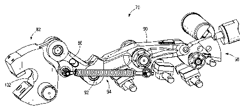
[0023] As shown in FIGS. 4 and 5, the latch mechanism 70 is positioned on
the dipper door
62 (FIG. 4). The latch mechanism 70 includes a primary cam or primary latch
member 82, a first
link 86 pivotably coupled to the primary latch member 82, a second link 90
pivotably coupled to
the first link 86 at a pivot joint 92, a spring assembly 94, and a secondary
cam or secondary latch
98. The latch mechanism 70 is moveable between a locked state and an unlocked
state. The
primary latch member 82 includes a jaw 102 that is pivotable relative to the
door 62. The jaw
102 is positioned to engage the latch pin 80 (FIG. 3) when the latch mechanism
70 is in the
locked state and is positioned to release the latch pin 80 (FIG. 3) when the
latch mechanism 70 is
in the unlocked state.
[0024] The second link 90 is pivotable relative to the door 62, and the
first link 86 is
pivotably coupled between the primary latch member 82 and the second link 90.
The spring
assembly 94 is coupled between the first link 86 and the second link 90, and
exerts a spring force
therebetween to pivot the first link 86 and the second link 90 about the pivot
joint 92. In the
embodiment shown in FIG. 5, the spring assembly 94 biases the latch mechanism
70 toward the
unlocked state. In one embodiment, the spring assembly 94 is positioned in an
over-center
configuration with the pivot joint 92, and the spring force biases the latch
mechanism 70 toward
either the locked state or the unlocked state depending on the relative
position of the pivot joint
92 with respect to the spring assembly 94. Also, in the illustrated
embodiment, the latch
mechanism 70 includes a spring assembly 94 positioned on each side of the
first link 86 and the
second link 90.
[0025] The secondary latch 98 engages an end of the second link 90 to
maintain the latch
mechanism 70 in the locked state. The weight of the dipper door 62 and
material supported
within the dipper body 58 cause the latch pin 80 to exert a reaction force on
the latch mechanism
70. Actuating or releasing the secondary latch 98 permits the second link 90
to pivot, and the
reaction force of the latch pin 80 causes the primary latch member 82 to pivot
out of engagement
with the latch pin 80. The associated movement of the first link 86 and the
second link 90 causes
the pivot joint 92 to move, toggling the spring assembly 94 so that the spring
force biases the
latch mechanism 70 toward the unlocked state.
CA 02824913 2013-08-28
[0026] When the operator desires to close the dipper door 62, the dipper 34
is moved to a
tuck position so that the door 62 pivots to the closed position. The latch pin
80 contacts with
primary latch member 82, pivoting the components of the latch mechanism 70 to
the locked
state. The movement of the pivot joint 92 toggles the spring assembly 94 so
that the spring
assembly 94 biases the latch mechanism 70 toward the locked state. The
secondary latch 98
engages the end of the second link 90 to hold the latch mechanism 70 in the
locked state. The
operation of the latch mechanism 70 is described in further detail in U.S.
Patent Application No.
12/986,933, filed January 7, 2011, the entire contents of which are
incorporated herein by
reference.
[0027] As shown in FIG. 6, the spring assembly 94 includes a first support
106, a second
support 110, and a spring element such as a coil spring 114 extending between
the first support
106 and the second support 110. Referring to FIG. 7, the first support 106
includes a first plug
120, a first bolt 124, and a first retaining collar 128. The first plug 120 is
an elongated member
having a first end 136, a second end 140, and a bore 144 extending
longitudinally through the
first plug 120 between the first end 136 and the second end 140. The first
plug 120 further
includes a threaded or grooved portion 148 proximate the first end 136. The
first bolt 124 is
inserted through the bore 144 from the first end 136 and extends through the
first plug 120 so
that an end of the bolt 124 is positioned away from the grooved portion 148.
The first retaining
collar 128 is positioned on the first plug 120 proximate the second end 140.
[0028] Similarly, the second support 110 includes a second plug 152, a
second bolt 156, a
second retaining collar 160, and a nut 164. The second plug 152 is an
elongated member having
a first end 168, a second end 172, and a bore 176 extending longitudinally
through the second
plug 152 between the first end 168 and the second end 172. The second plug 152
further
includes a threaded or grooved portion 180 proximate the first end 168. In the
illustrated
embodiment, the second bolt 156 is inserted through the bore 176 from the
second end 172 and
extends through the plug 152 so that an end of the bolt 156 is positioned
proximate the grooved
portion 180. The nut 164 is threaded onto the end of the second bolt 156 to
secure the bolt 156
to the second plug 152. The nut 164 can be retained in various ways such as
welding, for
example. The second bolt 156 includes an opening or eye 184 for coupling the
second support
6
CA 02824913 2013-08-28
110 to the first link 86 (FIG. 12). The second retaining collar 160 is
positioned on the second
plug 152 proximate the second end 172 between the eye 184 and the grooved
portion 180.
[0029] As best shown in FIGS. 8 and 9, the spring 114 is formed as stacked
coils, which
form an internal helical surface. As shown in FIG. 8, the first support 106 is
coupled to the
spring 114 by inserting the first end 136 of the first plug 120 into the
spring 114 such that the
grooved portion 148 receives the internal helical surface of a portion of the
coils. The first plug
120 is rotated, thereby threading the grooved portion 148 into the coils of
the spring 114.
Similarly, as shown in FIG. 9, the second support 110 is coupled to another
end of the spring 114
by inserting the first end 168 of the second plug 152 into the spring 114,
threading the grooved
portion 180 into the internal helical surface of the spring 114 as described
above with respect to
the first support 106.
[0030] In the illustrated embodiment, the first retaining collar 128
includes a pair of arms
192 forming a forked portion that receives one end of the spring 114.
Similarly, the second
retaining collar 160 includes a pair of arms 196 forming a forked portion that
receives the other
end of the spring 114. The retaining collars 128, 160 can be secured to the
plugs 120, 152,
respectively, in various ways including welding, for example. The arms 192,
196 provide anti-
rotation stops to prevent the spring 114 from unthreading or uncoiling from
the first plug 120 or
the second plug 154, respectively.
[0031] In the embodiment shown in FIGS. 10 and 11, the first bolt 124 (FIG.
11) is inserted
through a lug 204 coupled to the second link 90. The first bolt 124 is secured
to the lug 204 with
a nut 208. The connection between the first plug 120 and the second link 90
can be adjusted by
threading or unthreading the nut 208 with respect to the first bolt 124. In
addition, one or more
spacers 212 may be positioned on the first bolt 124 between the lug 204 and
the plug 120 or
between the lug 204 and the nut 208. These adjustments permit the user to
change the pre-load
on the spring assembly 94 as necessary to produce the desired response
behavior of the latch
mechanism 70 during operation.
[0032] As shown in FIG. 12, the eye 184 is positioned around a pin 216
coupled to the first
link 86 to pivotably couple the second support 110 to the first link 86. The
eye 184 can be
7
CA 02824913 2013-08-28
secured to the pin 216 in various ways, such as by a cotter pin inserted
through a hole in the pin
216.
[0033] The threaded engagement between each plug 120, 152 and the spring
114 provides a
secure coupling between the spring 114 and the supports 106, 110. In addition,
the threaded
engagement between the grooved surfaces 148, 180 and the internal helical
surface of the spring
reduces stress concentrations during operation by distributing the load over
multiple spring coils
instead of applying the load only at the ends of the spring 114. Reducing
stress concentrations
on the spring 114 prevents malfunction and improves reliability of the spring
assembly 94, which
in turn reduces the amount of time required for maintenance of the latch
mechanism 70.
100341 Thus, the invention provides, among other things, a spring assembly
for a latch
mechanism. Although the invention has been described in detail with reference
to certain
preferred embodiments, variations and modifications exist within the scope and
spirit of one or
more independent aspects of the invention as described. Various features and
advantages of the
invention are set forth in the following claims.
8