Note: Descriptions are shown in the official language in which they were submitted.
CA 02825084 2013-07-18
WO 2012/104630
PCT/GB2012/050209
1
INSERTING VIRTUAL CARRIER IN CONVENTIONAL OFDM HOST
CARRIER IN COMMUNICATIONS SYSTEM
TECHNICAL FIELD OF THE INVENTION
The present invention relates to methods, systems and apparatus for allocating
transmission resources and transmitting data in mobile telecommunication
systems.
BACKGROUND OF THE INVENTION
Third and fourth generation mobile telecommunication systems, such as those
based
on the 3GPP defined UMTS and Long Teim Evolution (LTE) architecture are able
to support
more sophisticated services than simple voice and messaging services offered
by previous
generations of mobile telecommunication systems.
For example, with the improved radio interface and enhanced data rates
provided by
LTE systems, a user is able to enjoy high data rate applications such as
mobile video
streaming and mobile video conferencing that would previously only have been
available via
a fixed line data connection. The demand to deploy third and fourth generation
networks is
therefore strong and the coverage area of these networks, i.e. geographic
locations where
access to the networks is possible, is expected to increase rapidly.
The anticipated widespread deployment of third and fourth generation networks
has
led to the parallel development of a class of devices and applications which,
rather than taking
advantage of the high data rates available, instead take advantage of the
robust radio interface
and increasing ubiquity of the coverage area. Examples include so-called
machine type
communication (MTC) applications, which are typified by semi-autonomous or
autonomous
wireless communication devices (i.e. MTC devices) communicating small amounts
of data on
a relatively infrequent basis. Examples include so-called smart meters which,
for example, are
located in a customer's house and periodically transmit information back to a
central MTC
server data relating to the customers consumption of a utility such as gas,
water, electricity
and so on.
Whilst it can be convenient for a terminal such as an MTC type terminal to
take
advantage of the wide coverage area provided by a third or fourth generation
mobile
telecommunication network there are at present disadvantages. Unlike a
conventional third or
fourth generation mobile terminal such as a smartphone, an MTC-type terminal
is preferably
relatively simple and inexpensive. The type of functions performed by the MTC-
type terminal
CA 02825084 2013-07-18
WO 2012/104630 PCT/GB2012/050209
2
(e.g. collecting and reporting back data) do not require particularly complex
processing to
perform. However, third and fourth generation mobile telecommunication
networks typically
employ advanced data modulation techniques on the radio interface which can
require more
complex and expensive radio transceivers to implement. It is usually justified
to include such
complex transceivers in a smartphone as a smartphone will typically require a
powerful
processor to perform typical smartphone type functions. However, as indicated
above, there is
now a desire to use relatively inexpensive and less complex devices to
communicate using
LTE type networks.
CA 02825084 2013-07-18
WO 2012/104630
PCT/GB2012/050209
3
SUMMARY OF THE INVENTION
According to a first aspect of the present invention there is provided a base
station for
communicating data to and from a plurality of mobile terminals over a
plurality of OFDM
sub-carriers within a coverage area provided by the base station. The base
station arranged to
allocate transmission resources provided by a first group of the plurality of
OFDM sub-
carriers within a first frequency band to mobile tenninals of a first type and
to allocate
transmission resources provided by a second group of the plurality of OFDM sub-
carriers
within a second frequency band to ter ________________________________________
uinals of a second type, the second group being smaller
than the first group and the second frequency band being selected from within
the first
frequency band. The base station is also arranged to transmit control
information comprising
resource allocation information for terminals of the first type over a first
bandwidth
corresponding to the combined first and second groups of OFDM sub-carriers and
to transmit
control information comprising resource allocation information for terminals
of the second
type over a second bandwidth corresponding to the second group of OFDM sub-
carriers.
In conventional OFDM based mobile telecommunication networks, control data is
typically transmitted from the network to the mobile terminals in a control
channel which
spans substantially the whole of the bandwidth of the signal transmitted from
the base station.
Normally a mobile terminal cannot operate within the network unless this
control data is
received and decoded and therefore the use of mobile terminals that operate
with a bandwidth
that is less than the whole bandwidth of the base station is precluded.
However, in accordance with this aspect of the invention, a subset of the OFDM
sub-
carriers are defined that are arranged across a reduced bandwidth. Data for
reduced capability
mobile terminals, including control data, can be separately transmitted on
this subset of the
OFDM sub-carriers.
This subset of the OFDM sub-carriers forms a "virtual carrier" within a
conventional
OFDM type downlink carrier (i.e. a "host carrier"). Unlike data transmitted on
a conventional
OFDM type downlink carrier, data transmitted on the virtual carrier can be
received and
decoded without needing to process the full bandwidth of the downlink host
OFDM carrier.
Accordingly, data transmitted on the virtual carrier can be received and
decoded using a
reduced complexity transceiver unit.
Devices provided with such a reduced complexity receiver unit (onwards
referred to as
"virtual carrier terminals") can be constructed to be less complex and less
expensive than
CA 02825084 2013-07-18
WO 2012/104630
PCT/GB2012/050209
4
conventional LTE type devices (onwards referred to generally as LTE
terminals).
Accordingly, the widespread deployment of devices for MTC type applications
within an LTE
type network which was previously impractical due to the prohibitive cost of
conventional
LTE terminals is now more practical because of the reduced cost of the virtual
carrier
terminals made possible by the provision of the virtual carrier.
Furthermore, in some examples, the virtual carrier inserted within the host
carrier can
be used to provide a logically distinct "network within a network". In other
words data being
transmitted via the virtual carrier can be treated as logically distinct from
the data transmitted
by the host carrier network. The virtual carrier can therefore be used to
provide a so-called
dedicated messaging network (DMN) which is "laid over" a conventional network
and used to
communicate messaging data to DMN devices (i.e. virtual carrier terminals).
In one embodiment of the invention in which the second group of the plurality
of the
OFDM sub-carriers form a virtual carrier inserted in the first group of the
plurality of the
OFDM sub-carriers and the first group of the plurality of the OFDM sub-
carriers form a host
carrier, the base station is arranged to transmit data to the terminals of the
first type on the
host carrier and transmitting data to or from the terminals of the second type
on the virtual
carrier.
In accordance with this embodiment, the definition of a virtual carrier
provides a
convenient mechanism by which data transmitted to terminals of the second type
(e.g. reduced
capability terminals) can be logically distinguished from data transmitted to
terminals of the
first type (e.g. conventional terminals). In some examples multiple virtual
carriers are
provided.
In accordance with one embodiment of the invention, the base station is
arranged to
transmit reference signals for use by both the terminals of the first type and
terminals of the
second type in the virtual carrier. In one example this comprises transmitting
additional
reference signals for use by terminals of the second type in the virtual
carrier. This enables
terminals of the second type (e.g. the reduced capability terminals) to
improve the quality of
the channel estimation which would otherwise be reduced in quality by virtue
of the limited
number of reference signals transmitted in the virtual carrier.
Various further aspects and embodiments of the invention are provided in the
appended claims.
CA 02825084 2013-07-18
WO 2012/104630
PCT/GB2012/050209
BRIEF DESCRIPTION OF DRAWINGS
Embodiments of the present invention will now be described by way of example
only
with reference to the accompanying drawings where like parts are provided with
5 corresponding reference numerals and in which:
Figure 1 provides a schematic diagram illustrating an example of a
conventional
mobile telecommunication network;
Figure 2 provides a schematic diagram illustrating a conventional LTE radio
frame;
Figure 3 provides a schematic diagram illustrating an example of a
conventional LTE
downlink radio sub-frame;
Figure 4 provides a schematic diagram illustrating a conventional LTE "camp-
on"
procedure;
Figure 5 provides a schematic diagram illustrating an LTE downlink radio sub-
frame
in which a virtual carrier has been inserted in accordance with an embodiment
of the
invention;
Figure 6 provides a schematic diagram illustrating an adapted LTE "camp-on"
procedure for camping on to a virtual carrier;
Figure 7 provides a schematic diagram illustrating LTE downlink radio sub-
frames in
accordance with an embodiment of the present invention;
Figure 8 provides a schematic diagram illustrating a physical broadcast
channel
(PBCH);
Figure 9 provides a schematic diagram illustrating an LTE downlink radio sub-
frame
in accordance with an embodiment of the present invention;
Figure 10 provides a schematic diagram illustrating an LTE downlink radio sub-
frame
in which a virtual carrier has been inserted in accordance with an embodiment
of the
invention;
Figures 11A to 11D provide schematic diagrams illustrating positioning of
location
signals within a LTE downlink sub-frame according to embodiments of the
present invention;
Figure 12 provides a schematic diagram illustrating a group of sub-frames in
which
two virtual carriers change location within a host carrier band according to
an embodiment of
the present invention;
CA 02825084 2013-07-18
WO 2012/104630 PCT/GB2012/050209
6
Figures 13A to 13C provide schematic diagrams illustrating LTE uplink sub-
frames in
which an uplink virtual carrier has been inserted in accordance with an
embodiment of the
present invention, and
Figure 14 provides a schematic diagram showing part of an adapted LTE mobile
telecommunication network arranged in accordance with an example of the
present invention.
CA 02825084 2013-07-18
WO 2012/104630
PCT/GB2012/050209
7
DESCRIPTION OF EXAMPLE EMBODIMENTS
Conventional Network
Figure 1 provides a schematic diagram illustrating the basic functionality of
a
conventional mobile telecommunications network.
The network includes a plurality of base stations 101 connected to a core
network 102.
Each base station provides a coverage area 103 (i.e. a cell) within which data
can be
communicated to and from mobile terminals 104. Data is transmitted from a base
station 101
to a mobile terminal 104 within a coverage area 103 via a radio downlink. Data
is transmitted
from a mobile teiniinal 104 to a base station 101 via a radio uplink. The core
network 102
routes data to and from the mobile terminals 104 and provides functions such
as
authentication, mobility management, charging and so on.
Mobile telecommunications systems such as those arranged in accordance with
the
3GPP defined Long Term Evolution (LTE) architecture use an orthogonal
frequency division
multiplex (OFDM) based interface for the radio downlink (so-called OFDMA) and
the radio
uplink (so-called SC-FDMA). Data is transmitted on the uplink and on the
downlink on a
plurality of orthogonal sub-carriers. Figure 2 shows a schematic diagram
illustrating an
OFDM based LTE downlink radio frame 201. The LTE downlink radio frame is
transmitted
from an LTE base station (known as an enhanced Node B) and lasts 10 ms. The
downlink
radio frame comprises ten sub-frames, each sub-frame lasting 1 ms. A primary
synchronisation signal (PSS) and a secondary synchronisation signal (SSS) are
transmitted in
the first and sixth sub-frames of the LTE frame. A primary broadcast channel
(PBCH) is
transmitted in the first sub-frame of the LTE frame. The PSS, SSS and PBCH are
discussed in
more detail below.
Figure 3 provides a schematic diagram providing a grid which illustrates the
structure
of an example of a conventional downlink LTE sub-frame. The sub-frame
comprises a
predetermined number of symbols which are transmitted over a lms period. Each
symbol
comprises a predetermined number of orthogonal sub-carriers distributed across
the
bandwidth of the downlink radio carrier.
The example sub-frame shown in Figure 3 comprises 14 symbols and 1200 sub-
carriers spaced across a 20MHz bandwidth. The smallest unit on which data can
be
transmitted in LTE is twelve sub-carriers transmitted over one sub-frame. For
clarity, in
CA 02825084 2013-07-18
WO 2012/104630
PCT/GB2012/050209
8
Figure 3, each individual resource element is not shown, instead each
individual box in the
sub-frame grid corresponds to twelve sub-carriers transmitted on one symbol.
Figure 3 shows resource allocations for four LTE terminals 340, 341, 342, 343.
For
example, the resource allocation 342 for a first LTE terminal (UE 1) extends
over five blocks
of twelve sub-carriers, the resource allocation 343 for a second LTE terminal
(UE2) extends
over six blocks of twelve sub-carriers and so on.
Control channel data is transmitted in a control region 300 of the sub-frame
comprising the first n symbols of the sub-frame where n can vary between one
and three
symbols for channel bandwidths of 3MHz or greater and where n can vary between
two and
four symbols for channel bandwidths of 1.4MHz. For clarity, the following
description relates
to host carriers with channel bandwidth of 3MHz or greater where the maximum
value of n
will be 3. The data transmitted in the control region 300 includes data
transmitted on the
physical downlink control channel (PDCCH), the physical control foimat
indicator channel
(PCFICH) and the physical HARQ indicator channel (PHICH).
The PDCCH contains control data indicating which sub-carriers on which symbols
of
the sub-frame have been allocated to specific LTE tettninals. Thus, the PDCCH
data
transmitted in the control region 300 of the sub-frame shown in Figure 3 would
indicate that
UE1 has been allocated the first block of resources 342, that UE2 has been
allocated the
second block of resources 343, and so on. The PCFICH contains control data
indicating the
size of the control region (i.e. between one and three symbols) and the PHICH
contains
HARQ (Hybrid Automatic Request) data indicating whether or not previously
transmitted
uplink data has been successfully received by the network.
In certain sub-frames, symbols in a central band 310 of the sub-frame are used
for the
transmission of information including the primary synchronisation signal
(PSS), the
secondary synchronisation signal (SSS) and the physical broadcast channel
(PBCH). This
central band 310 is typically 72 sub-carriers wide (corresponding to a
transmission bandwidth
of 1.08 MHz). The PSS and SSS are synchronisation signals that once detected
allow the
LTE terminal 104 to achieve frame synchronisation and determine the cell
identity of the
enhanced Node B transmitting the downlink signal. The PBCH carries information
about the
cell, comprising a master information block (MIB) that includes parameters
that the LTE
terminals require to access the cell. Data transmitted to individual LTE
terminals on the
physical downlink shared channel (PDSCH) can be transmitted in the remaining
blocks of
CA 02825084 2013-07-18
WO 2012/104630
PCT/GB2012/050209
9
resource elements of the sub-frame. Further explanation of these channels is
provided in the
following sections.
Figure 3 also shows a region of PDSCH containing system information and
extending
over a bandwidth of R344.
The number of sub-carriers in an LTE channel can vary depending on the
configuration of the transmission network. Typically this variation is from 72
sub carriers
contained within a 1.4MHz channel bandwidth to 1200 sub-carriers contained
within a
20MHz channel bandwidth as shown in Figure 3. As is known in the art, data
transmitted on
the PDCCH, PCFICH and PHICH is typically distributed on the sub-carriers
across the entire
bandwidth of the sub-frame. Therefore a conventional LTE terminal must be able
to receive
the entire bandwidth of the sub-frame in order to receive and decode the
control region.
Conventional Camp on Procedure
Figure 4 illustrates an LTE "camp-on" process, that is the process followed by
a
terminal so that it can decode downlink transmissions which are sent by a base
station via a
downlink channel on a carrier band. Using this process, the terminal can
identify the parts of
the transmissions that include system information for the cell and thus decode
configuration
information for the cell.
As can be seen in Figure 4, in a conventional LTE camp-on procedure, the
terminal
first synchronizes with the base station (step 400) using the PSS and SSS in
the centre band
310 of the carrier as mentioned above. As can be seen with reference to Figure
3 the centre
band 310 has a bandwidth range R310, where the band is at the centre of the
carrier (i.e.
occupying the central sub-carriers).
The terminal detects this centre band and detects the PSS and SSS which
indicate the
cyclic prefix duration and the Cell ID. In LTE the PSS and SSS are only
transmitted in the
first and sixth sub-frames of each radio frame. Of course, in a different
system, for example a
non-LTE system, the band 310 may not be at the centre of the carrier band and
may be wider
or narrower than 72 sub-carriers or 1.08 MHz. Likewise, the sub-frames may be
of a different
size or sizes.
The terminal then decodes the PBCH (step 401), also carried on the centre band
310,
where the PBCH includes in particular the Master Infoimation Block (MIB). The
MIB
indicates in particular the bandwidth R320 of the downlink carrier, the System
Frame Number
CA 02825084 2013-07-18
WO 2012/104630
PCT/GB2012/050209
(SFN), and the PHICH configuration. Using the MIB carried on the PBCH, the
terminal can
then be made aware of the bandwidth R320 of the carrier. Because the terminal
also knows
where the central band 310 is, it knows the exact range R320 of the downlink
carrier.
For each sub-frame, the terminal then decodes the PCFICH which is distributed
across
5 the entire width of carrier 320 (step 402). As discussed above, an LTE
downlink carrier can
be up to 20 MHz wide (1200 sub-carriers) and an LTE terminal therefore has to
have the
capability to receive and decode transmissions on a 20 MHz bandwidth in order
to decode the
PCFICH. At that stage, with a 20MHz carrier band, the terminal operates at a
much larger
bandwidth (bandwidth of R320) than during steps 400 and 401 (bandwidth of
R310) relating to
10 synchronization and PBCH decoding.
The terminal then ascertains the PHICH locations (step 403) and decodes the
PDCCH
(step 404), in particular for identifying system information transmissions and
for identifying
its personal allocation grants. The allocation grants are used by the terminal
to locate system
information and to locate its data in the PDSCH. Both system information and
personal
allocations are transmitted on PDSCH and scheduled within the carrier band
320. Steps 403
and 404 also require the terminal to operate on the entire bandwidth R320 of
the carrier band.
At steps 402 to 404, the terminal decodes information contained in the control
region
300 of a sub-frame. As explained above, in LTE, the three control channels
mentioned above
(PCFICH, PHICH and PDCCH) can be found across the control region 300 of the
carrier
where the control regions extends over the range R320 and occupies the first
one, two or three
OFDM symbols of each sub-frame as discussed above. In a sub-frame, typically
the control
channels do not use all the resource elements within the control region 300,
but they are
scattered across the entire region, such that a LTE terminal has to be able to
simultaneously
receive the entire control region 300 for decoding each of the three control
channels.
The terminal can then decode the PDSCH (step 405) which contains system
information or data transmitted for this terminal.
As explained above, in an LTE sub-frame the PDSCH generally occupies groups of
resource elements which are neither in the control region nor in the resource
elements
occupied by PSS, SSS or PBCH. The data in the blocks of resource elements 340,
341, 342,
343 shown in Figure 3 have a smaller bandwidth than the bandwidth of the
entire carrier
although to decode these blocks, a terminal first receives the PDCCH across
the frequency
range R320 and if the PDCCH indicates that a PDSCH resource should be decoded,
once it has
CA 02825084 2013-07-18
WO 2012/104630
PCT/GB2012/050209
11
received the entire sub-frame, it then decodes only the PDSCH in only the
relevant frequency
range indicated by the PDCCH. So for example, UE 1 discussed above decodes the
whole
control region 300 and then the data in the resource block 342.
Virtual Downlink Carrier
Certain classes of devices, such as MTC devices (e.g. semi-autonomous or
autonomous wireless communication devices such as smart meters as discussed
above),
support communication applications that are characterised by the transmission
of small
amounts of data at relatively infrequent intervals and can thus be
considerably less complex
than conventional LTE terminals. In many scenarios, providing low capability
terminals such
as those with a conventional high-performance LTE receiver unit capable of
receiving and
processing data from an LTE downlink frame across the full carrier bandwidth
can be overly
complex for a device which only needs to communicate small amounts of data.
This may
therefore limit the practicality of a widespread deployment of low capability
MTC type
devices in an LTE network. It is preferable instead to provide low capability
terminals such as
MTC devices with a simpler receiver unit which is more proportionate with the
amount of
data likely to be transmitted to the terminal. As set out below, in accordance
with examples of
the present invention a "virtual carrier" is inserted in a conventional OFDM
type downlink
carrier (i.e. a "host carrier"). Unlike data transmitted on a conventional
OFDM type downlink
carrier, data transmitted on the virtual carrier can be received and decoded
without needing to
process the full bandwidth of the downlink host OFDM carrier. Accordingly,
data transmitted
on the virtual carrier can be received and decoded using a reduced complexity
receiver unit.
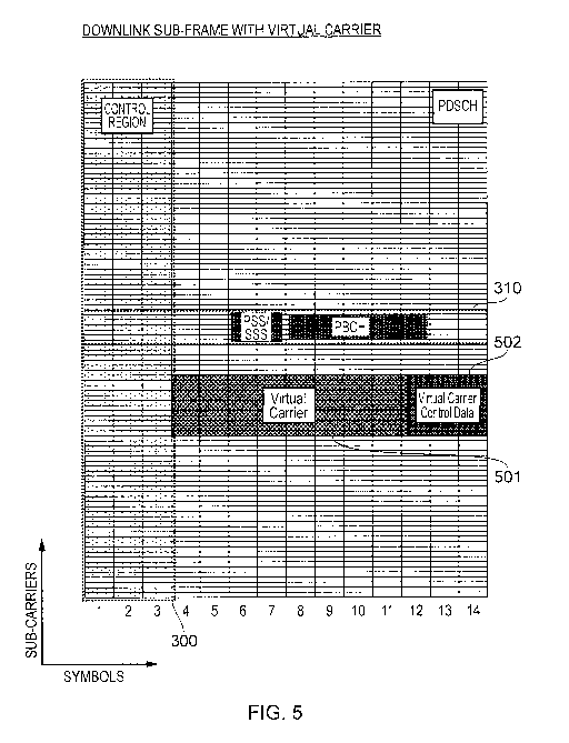
Figure 5 provides a schematic diagram illustrating an LTE downlink sub-frame
which
includes a virtual carrier inserted in a host carrier in accordance with an
example of the
present invention.
In keeping with a conventional LTE downlink sub-frame, the first n symbols (n
is
three in Figure 5) form the control region 300 which is reserved for the
transmission of
downlink control data such as data transmitted on the PDCCH. However, as can
be seen from
Figure 5, outside of the control region 300 the LTE downlink sub-frame
includes a group of
resource elements below the central band 310 which form a virtual carrier 501.
As will
become clear, the virtual carrier 501 is adapted so that data transmitted on
the virtual carrier
501 can be treated as logically distinct from the data transmitted in the
remaining parts of the
CA 02825084 2013-07-18
WO 2012/104630
PCT/GB2012/050209
12
host carrier and can be decoded without first decoding all the control data
from the control
region 300. Although Figure 5 shows the virtual carrier occupying frequency
resources below
the centre band, in general the virtual carrier can alternatively either
occupy frequency
resources above the centre band or frequency resources including the centre
band. If the
virtual carrier is configured to overlap any resources used by the PSS, SSS or
PBCH of the
host carrier, or any other signal transmitted by the host carrier that a
mobile terminal
operating on the host carrier would require for correct operation and expect
to find in a known
pre-determined location, the signals on the virtual carrier can be arranged
such that these
aspects of the host carrier signal are maintained.
As can be seen from Figure 5, data transmitted on the virtual carrier 501 is
transmitted
across a limited bandwidth. This could be any suitable bandwidth providing it
is smaller than
that of the host carrier. In the example shown in Figure 5 the virtual carrier
is transmitted
across a bandwidth comprising 12 blocks of 12 sub-carriers (i.e. 144 sub-
carriers) which is
equivalent to a 2.16MHz transmission bandwidth. Accordingly, a terminal
receiving data
transmitted on the virtual carrier need only be equipped with a receiver
capable of receiving
and processing data transmitted over a bandwidth of 2.16MHz. This enables low
capability
terminals (for example MTC type terminals) to be provided with simplified
receiver units yet
still be able to operate within an OFDM type communication network which, as
explained
above, conventionally requires terminals to be equipped with receivers capable
of receiving
and processing an OFDM signal across the entire bandwidth of the signal.
As explained above, in OFDM based mobile communication systems such as LTE,
downlink data is dynamically assigned to be transmitted on different sub-
carriers on a sub-
frame by sub-frame basis. Accordingly, in every sub-frame the network must
signal which
sub-carriers on which symbols contain data relevant to which terminals (i.e.
downlink grant
signalling).
As can be seen from Figure 3, in a conventional downlink LTE sub-frame this
information is transmitted on the PDCCH during the first symbol or symbols of
the sub-
frame. However, as previously explained, the information transmitted in the
PDCCH is spread
across the entire bandwidth of the sub-frame and therefore cannot be received
by a mobile
communication terminal with a simplified receiver unit capable only of
receiving the reduced
bandwidth virtual carrier.
CA 02825084 2013-07-18
WO 2012/104630
PCT/GB2012/050209
13
Accordingly, as can be seen in Figure 5, the final symbols of the virtual
carrier can be
reserved as a virtual carrier control region 502 which is allocated for the
transmission of
control data indicating which resource elements of the virtual carrier 501
have been allocated.
In some examples the number of symbols comprising the virtual carrier control
region 502 is
fixed for example three symbols. In other examples the virtual carrier control
region 502 can
vary in size, for example between one and three symbols.
The virtual carrier control region can be located at any suitable position
within the
virtual carrier for example in the first few symbols of the virtual carrier.
In the example of
Figure 5 this could mean positioning the virtual carrier control region on the
fourth, fifth and
sixth symbols. However, fixing the position of the virtual carrier control
region in the final
symbols of the sub-frame can provide an advantage because the position of the
virtual carrier
control region need not vary even if the number of symbols of the host carrier
control region
varies. This simplifies the processing undertaken by mobile communication
terminals
receiving data on the virtual carrier because there is no need for them to
determine the
position of the virtual carrier control region every sub-frame as it is known
that it will always
be positioned in the final symbols of the sub-frame.
In a further embodiment, the virtual carrier control symbols may reference
virtual
carrier PDSCH transmissions in a separate sub-frame.
In some examples the virtual carrier may be located within the centre band 310
of the
downlink sub-frame. This would minimise the reduction in host carrier PDSCH
resources
caused by the insertion of a virtual carrier since the resources occupied by
the PSS/SSS and
PBCH would be contained within the virtual carrier region and not the host
carrier PDSCGH
region. Therefore, depending on for example the expected virtual carrier
throughput, the
location of a virtual carrier can be appropriately chosen to either exist
inside or outside the
centre band according to whether the host or virtual carrier is chosen to bear
the overhead of
the PSS, SSS and PBCH.
Virtual Carrier "Camp-On" Process
As explained above, before a conventional LTE terminal can begin transmitting
and
receiving data in a cell, it must first camp on to the cell. An adapted camp-
on process must
also be provided before terminals can receive data on the virtual carrier.
CA 02825084 2013-07-18
WO 2012/104630
PCT/GB2012/050209
14
Figure 6 shows a flow diagram illustrating a camp-on process according to an
example
of the present invention. The virtual carrier camp-on process is explained
with reference to the
sub-frame shown in Figure 5 in which a virtual carrier with a bandwidth of 144
sub-carriers is
inserted in a host carrier with a bandwidth of 1200 sub-carriers. As discussed
above, a
terminal having a receiver unit with an operational bandwidth of less than
that of the host
carrier cannot decode data in the control region of sub-frames of the host
carrier. However,
providing the receiver unit of a terminal has an operational bandwidth of at
least twelve
blocks of twelve sub-carriers (i.e. 2.16 MHz) then it can receive data
transmitted on the
example virtual carrier 502.
In the example of Figure 6, the first steps 400 and 401 are the same as the
conventional camp-on process shown in Figure 4, although a virtual carrier
terminal may
extract additional information from the MIB as described below. Both terminals
can use the
PSS/SSS and PBCH to synchronize with the base station using the information
carried on the
72 sub-carrier centre band within the host carrier. However, where the
conventional LTE
terminals then continue with the process by performing the PCFICH decoding
step 402,
which requires a receiver unit capable of receiving and decoding the host
carrier control
region 300, a terminal camping on to the cell to receive data on the virtual
carrier (referred to
from now on as a "virtual carrier terminal") performs steps 606 and 607
instead.
In a further embodiment of the present invention a separate synchronisation
and
PBCH functionality can be provided for the virtual carrier device as opposed
to re-using the
same conventional initial camp-on processes of steps 400 and 401 of the host
carrier device.
At step 606, the virtual carrier terminal locates a virtual carrier, if any is
provided
within the host carrier, using a virtual carrier-specific step. Various
possible embodiments of
this step are discussed further below. Once the virtual carrier terminal has
located a virtual
carrier, it can access information within the virtual carrier. For example, if
the virtual carrier
mirrors the conventional LTE resource allocation method, the virtual carrier
terminal may
then decode control portions within the virtual carrier, which can for example
indicate which
resource elements within the virtual carrier have been allocated for a
specific virtual carrier
terminal or for system information. For example, Figure 7 shows the blocks of
resource
elements 350 to 352 within virtual carrier 330 that have been allocated for
the sub-frame SF2.
However, there is no requirement for the virtual carrier terminal to follow or
mirror the
CA 02825084 2013-07-18
WO 2012/104630
PCT/GB2012/050209
conventional LTE process (e.g. steps 402-404) and these steps may for example
be
implemented very differently for a virtual carrier camp-on process.
Regardless of the virtual carrier terminal following a LTE-like step or a
different type
of step when performing step 607, the virtual carrier terminal can then decode
the allocated
5
resource elements at step 608 and thereby receive data transmitted by the base
station. The
data decoded in step 608 will include the remainder of the system information
containing
details of the network configuration.
Even though the virtual carrier terminal does not have the bandwidth
capabilities to
decode and receive downlink data if it was transmitted in the host carrier
using conventional
10
LTE, it can still access a virtual carrier within the host carrier having a
limited bandwidth
whilst re-using the initial LTE steps. Step 608 may also be implemented in a
LTE-like
manner or in a different manner. For example, the virtual carrier terminals
may share a
virtual carrier and have grants allocated to manage the virtual carrier
sharing as shown in SF2
in Figure 7, or, in another example, a virtual carrier terminal may have the
entire virtual
15
carrier allocated for its own downlink transmissions, or the virtual carrier
may be entirely
allocated to a virtual carrier terminal for a certain number of sub-frame
only, etc.
There is therefore a degree of flexibility provided for this virtual carrier
camp-on
process. There is for example given the choice to adjust the balance between
re-using or
mirroring conventional LTE steps or processes, thereby reducing the terminal
complexity and
the need to implement new elements, and adding new virtual carrier specific
aspects or
implementations, thereby potentially optimizing the use of narrow-band virtual
carriers, as
LTE has been designed with the larger-band host carriers in mind.
Downlink Virtual Carrier Detection
As discussed above, the virtual carrier terminal has to locate the virtual
carrier before
it can receive and decode the virtual carrier transmissions. Several options
are available for
the virtual carrier presence and location determination, which can be
implemented separately
or in combination. Some of these options are discussed below.
To facilitate the virtual carrier detection, the virtual carrier location
information may
be provided to the virtual carrier terminal such that it can locate the
virtual carrier, if any
exists, more easily. For example, such location information may comprise an
indication that
one or more virtual carriers are provided within the host carrier or that the
host carrier does
CA 02825084 2013-07-18
WO 2012/104630
PCT/GB2012/050209
16
not currently provide any virtual carrier. It may also comprise an indication
of the virtual
carrier's bandwidth, for example in MHz or blocks of resource elements.
Alternatively, or in
combination, the virtual carrier location information may comprise the virtual
carrier's centre
frequency and bandwidth, thereby giving the virtual carrier terminal the exact
location and
bandwidth of any active virtual carrier. In the event that the virtual carrier
is to be found at a
different frequency position in each sub-frame, according for example to a
pseudo-random
hoping algorithm, the location information can for example indicate a pseudo
random
parameter. Such parameters may include a starting frame and parameters used
for the pseudo-
random algorithm. Using these pseudo-random parameters, the virtual carrier
terminal can
then know where the virtual carrier can be found for any sub-frame.
An advantageous implementation which would require little change to the
virtual
carrier terminal (compared with a conventional LTE terminal) is to include
this location
information in the PBCH, which already carries the Master Information Block,
or MIB in the
host carrier centre band. As shown in Figure 8, the MIB consists of 24 bits (3
bits to indicate
DL bandwidth, 8 bits to indicate the System Frame Number or SFN, and 3 bits
regarding the
PHICH configuration). The MIB therefore comprises 10 spare bits that can be
used to carry
location information in respect of one or more virtual carriers. For example,
Figure 9 shows
an example where the PBCH includes the MIB and location information ("LI") for
pointing
any virtual carrier terminal to a virtual carrier.
Alternatively, this Location Information can be provided for example in the
centre
band, outside of the PBCH. It can for example be always provided after and
adjacent to the
PBCH. By providing the Location Information in the centre band but outside of
the PBCH,
the conventional PBCH is not modified for the purpose of using virtual
carriers, but a virtual
carrier terminal will easily find the location information in order to detect
the virtual carrier, if
any.
The virtual carrier location information, if provided, can be provided
elsewhere in the
host carrier, but it is advantageous to provide it in the centre band because
the virtual carrier
terminal will preferentially configure its receiver to operate on the centre
band and the virtual
carrier terminal then does not need to adjust its receiver settings for
finding the location
information.
CA 02825084 2013-07-18
WO 2012/104630
PCT/GB2012/050209
17
Depending on the amount of virtual carrier location information provided, the
virtual
carrier terminal can either adjust its receiver to receive the virtual carrier
transmissions, or it
may require further location information before it can do so.
If for example, the virtual carrier terminal was provided with location
information
indicating a virtual carrier presence and/or a virtual carrier bandwidth but
not indicating any
details as to the exact virtual carrier frequency range, or if the virtual
carrier terminal was not
provided with any location information, the virtual carrier terminal can then
scan the host
carrier for a virtual carrier (e.g. performing a so-called blind search
process). Scanning the
host carrier for a virtual carrier can be based on different approaches, some
of which will be
presented below.
According to a first approach, the virtual carrier can only be inserted in
certain pre-
determined locations, as illustrated for example in Figure 10 for a four-
location example. The
virtual carrier terminal then scans the four locations L 1-L4 for any virtual
carrier. If and
when the virtual carrier terminal detects a virtual carrier, it can then "camp-
on" the virtual
carrier to receive downlink data. In this approach, the virtual carrier
terminal has to know the
possible virtual carrier locations in advance, for example by reading an
internal memory.
Detection of a virtual carrier could be accomplished by trying to decode a
known physical
channel on the virtual carrier. The successful decoding of such a channel,
indicated for
example by a successful cyclic redundancy check (CRC) on decoded data, would
indicate the
successful location of a virtual carrier
According to a second approach, the virtual carrier may include location
signals such
that a virtual carrier terminal scanning the host carrier can detect such
signals to identify the
presence of a virtual carrier. Examples of possible location signals are
illustrated in Figures
11A to 11D. In the examples of Figures 11A to 11C, the virtual carrier
regularly sends an
arbitrary location signal such that a terminal scanning a frequency range
where the location
signal is would detect this signal. An "arbitrary" signal is meant to include
any signal that
does not carry any information as such, or is not meant to be interpreted, but
merely includes
a specific signal or pattern that a virtual carrier terminal can detect. This
can for example be a
series of positive bits across the entire location signal, an alternation of 0
and 1 across the
location signal, or any other suitable arbitrary signal. It is noteworthy that
the location signal
may be made of adjacent blocks of resource elements or may be formed of non
adjacent
CA 02825084 2013-07-18
WO 2012/104630
PCT/GB2012/050209
18
blocks. For example, it may be located at every other block of resource
elements at the top of
the virtual carrier.
In the example of Figure 11A, the location signal 353 extends across the range
R330 of
the virtual carrier 330 and is always found at the same position in the
virtual carrier within a
sub-frame. If the virtual carrier terminal knows where to look for a location
signal in a virtual
carrier sub-frame, it can then simplify its scanning process by only scanning
this position
within a sub-frame for a location signal. Figure 11B shows a similar example
where every
sub-frame includes a location signal 354 comprising two parts: one at the top
corner and one
at the bottom corner of the virtual carrier sub-frame, at the end of this sub-
frame. Such a
location signal may become useful if for example the virtual carrier terminal
does not know
the bandwidth of the virtual carrier in advance as it can facilitate a clear
detection of the top
and bottom edges of the virtual carrier band.
In the example of Figure 11C, a location signal 355 is provided in a first sub-
frame
SF1, but not in a second sub-frame SF2. The location signal can for example be
provided
every two sub-frames. The frequency of the location signals can be chosen to
adjust a balance
between reducing scanning time and reducing overhead. In other words, the more
often the
location signal is provided, the less long it takes a terminal to detect a
virtual carrier but the
more overhead there is.
In the example of Figure 11D, a location signal is provided where this
location signal
is not an arbitrary signal as in Figures 11A to 11C, but is a signal that
includes information for
virtual carrier tellninals. The virtual carrier teuninals can detect this
signal when they scan
for a virtual carrier and the signal may include infoiniation in respect of,
for example, the
virtual carrier bandwidth or any other virtual carrier-related information
(location or non-
location information). When detecting this signal, the virtual carrier
terminal can thereby
detect the presence and location of the virtual carrier. As shown in Figure
11D, the location
signal can, like an arbitrary location signal, be found at different locations
within the sub-
frame, and the location may vary on a per-sub-frame basis.
Dynamic Variation of Control Region Size of Host Carrier
As explained above, in LTE the number of symbols that make up the control
region of
a downlink sub-frame varies dynamically depending on the quantity of control
data that needs
to be transmitted. Typically, this variation is between one and three symbols.
As will be
CA 02825084 2013-07-18
WO 2012/104630
PCT/GB2012/050209
19
understood with reference to Figure 5, variation in the width of the host
carrier control region
will cause a corresponding variance in the number of symbols available for the
virtual carrier.
For example, as can be seen in Figure 5, when the control region is three
symbols in length
and there are 14 symbols in the sub-frame, the virtual carrier is eleven
symbols long.
However, if in the next sub-frame the control region of the host carrier were
reduced to one
symbol, there would be thirteen symbols available for the virtual carrier in
that sub-frame.
When a virtual carrier is inserted into a LTE host carrier, mobile
communication
terminals receiving data on the virtual carrier need to be able to determine
the number of
symbols in the control region of each host carrier sub-frame to deteiiiiine
the number of
symbols in the virtual carrier in that sub-frame if they are to be able to use
all available
symbols that are not used by the host carrier control region.
Conventionally, the number of symbols foiming the control region is signalled
in the
first symbol of every sub-frame in the PCFICH. However, the PCFICH is
typically distributed
across the entire bandwidth of the downlink LTE sub-frame and is therefore
transmitted on
sub-carriers which virtual carrier teiminals capable only of receiving the
virtual carrier cannot
receive. Accordingly, in one embodiment, any symbols across which the control
region could
possibly extend are predefined as null symbols on the virtual carrier, i.e.
the length of the
virtual sub-carrier is set at (m ¨ n) symbols, where m is the total number of
symbols in a sub-
frame and n is the maximum number of symbols of the control region. Thus,
resource
elements are never allocated for downlink data transmission on the virtual
carrier during the
first n symbols of any given sub-frame.
Although this embodiment is simple to implement it will be spectrally
inefficient
because during sub-frames when the control region of the host carrier has
fewer than the
maximum number of symbols, there will be unused symbols in the virtual
carrier.
In another embodiment, the number of symbols in the control region of the host
carrier
is explicitly signalled in the virtual carrier itself. Once the number of
symbols in the control
region of the host carrier is known, the number of symbols in the virtual
carrier can be
calculated by subtracting the total number of symbols in the sub-frame from
this number.
In one example an explicit indication of the host carrier control region size
is given by
certain information bits in the virtual carrier control region. In other words
an explicit
signalling message is inserted at a predefined position in the virtual carrier
control region 502.
CA 02825084 2013-07-18
WO 2012/104630
PCT/GB2012/050209
This predefined position is known by each terminal adapted to receive data on
the virtual
carrier.
In another example, the virtual carrier includes a predefined signal, the
location of
which indicates the number of symbols in the control region of the host
carriers. For example,
5 a
predefined signal could be transmitted on one of three predetermined blocks of
resource
elements. When a terminal receives the sub-frame it scans for the predefined
signal. If the
predefined signal is found in the first block of resource elements this
indicates that the control
region of the host carrier comprises one symbol; if the predefined signal is
found in the
second block of resource elements this indicates that the control region of
the host carrier
10
comprises two symbols and if the predefined signal is found in the third block
of resource
elements this indicates that the control region of the host carrier comprises
three symbols.
In another example, the virtual carrier terminal is arranged to first attempt
to decode
the virtual carrier assuming that the control region size of the host carrier
is one symbol. If
this is not successful, the virtual carrier terminal attempts to decode the
virtual carrier
15
assuming that the control region size of the host carrier is two and so on,
until the virtual
carrier terminal successfully decodes the virtual carrier.
Downlink Virtual Carrier Reference Signals
As is known in the art, in OFDM based transmission systems such as LTE a
number of
20 sub-
carriers in each symbol are typically reserved for the transmission of
reference signals.
The reference signals are transmitted on sub-carriers distributed throughout a
sub-frame
across the channel bandwidth and across the OFDM symbols. The reference
signals are
arranged in a repeating pattern and can thus be used by a receiver, employing
extrapolation
and interpolation techniques to estimate the channel function applied to the
data transmitted
on each sub-carrier. These reference signals are also typically used for
additional purposes
such as determining metrics for received signal power indications, automatic
frequency
control metrics and automatic gain control metrics. In LTE the positions of
the reference
signal bearing sub-carriers within each sub-frame are pre-defined and are
therefore known at
the receiver of each terminal.
In LTE downlink sub-frames, reference signals from each transmit antenna port
are
typically inserted on every sixth sub-carrier. Accordingly, if a virtual
carrier is inserted in an
LTE downlink sub-frame, even if the virtual carrier has a minimum bandwidth of
one
CA 02825084 2013-07-18
WO 2012/104630
PCT/GB2012/050209
21
resource block (i.e. twelve sub-carriers) the virtual carrier will include at
least some reference
signal bearing sub-carriers.
There are sufficient reference signal bearing sub-carriers provided in each
sub-frame
such that a receiver need not accurately receive every single reference signal
to decode the
data transmitted on the sub-frame. However, as will be understood the more
reference signals
that are received, the better a receiver will be able to estimate the channel
response and hence
fewer errors are typically introduced into the data decoded from the sub-
frame. Accordingly,
in order to preserve compatibility with LTE communication terminals receiving
data on the
host carrier, in some examples of the present invention, the sub-carrier
positions that would
contain reference signals in a conventional LTE sub-frame are retained in the
virtual carrier.
As will be understood, in accordance with examples of the present invention,
terminals arranged to receive only the virtual carrier receive a reduced
number of sub-carriers
compared to conventional LTE terminals which receive each sub-frame across the
entire
bandwidth of the sub-frame. As a result, the reduced capability terminals
receive fewer
reference signals over a narrower range of frequencies which may result in a
less accurate
channel estimation being generated.
In some examples a simplified virtual carrier terminal may have a lower
mobility
which requires fewer reference symbols to support channel estimation. However,
in some
examples of the present invention the downlink virtual carrier includes
additional reference
signal bearing sub-carriers to enhance the accuracy of the channel estimation
that the reduced
capability terminals can generate.
In some examples the positions of the additional reference bearing sub-
carriers are
such that they are systematically interspersed with respect to the positions
of the conventional
reference signal bearing sub-carriers thereby increasing the sampling
frequency of the channel
estimation when combined with the reference signals from the existing
reference signal
bearing sub-carriers. This allows an improved channel estimation of the
channel to be
generated by the reduced capability terminals across the bandwidth of the
virtual carrier. In
other examples, the positions of the additional reference bearing sub-carriers
are such that
they are systematically placed at the edge of the bandwidth of the virtual
carrier thereby
increasing the interpolation accuracy of the virtual carrier channel
estimates.
Alternative Virtual Carrier Arrangements
CA 02825084 2013-07-18
WO 2012/104630
PCT/GB2012/050209
22
So far examples of the invention have been described generally in terms of a
host
carrier in which a single virtual carrier has been inserted as shown for
example in Figure 5.
However, in some examples a host carrier may include more than one virtual
carrier as shown
for example in Figure 12. Figure 12 shows an example in which two virtual
carriers VC1
(330) and VC2 (331) are provided within a host carrier 320. In this example,
the two virtual
carriers change location within the host carrier band according to a pseudo-
random algorithm.
However, in other examples, one or both of the two virtual carriers may always
be found in
the same frequency range within the host carrier frequency range and/or may
change position
according to a different mechanism. In LTE, the number of virtual carriers
within a host
carrier is only limited by the size of the host carrier. However, too many
virtual carriers
within the host carrier may unduly limit the bandwidth available for
transmitting data to
conventional LTE terminals and an operator may therefore decide on a number of
virtual
carrier within a host carrier according to, for example, a ratio of
conventional LTE users /
virtual carrier users.
In some examples the number of active virtual carriers can be dynamically
adjusted
such that it fits the current needs of conventional LTE terminals and virtual
carrier terminals.
For example, if no virtual carrier terminal is connected or if their access is
to be intentionally
limited, the network can arrange to begin scheduling the transmission of data
to LTE
terminals within the sub-carriers previously reserved for the virtual carrier.
This process can
be reversed if the number of active virtual carrier telliinals begins to
increase. In some
examples the number of virtual carriers provided may be increased in response
to an increase
in the presence of virtual carrier terminals. For example if the number of
virtual terminals
present in a network or area of a network exceeds a threshold value, an
additional virtual
carrier is inserted in the host carrier. The network elements and/or network
operator can thus
activate or deactivate the virtual carriers whenever appropriate.
The virtual carrier shown for example in Figure 5 is 144 sub-carriers in
bandwidth.
However, in other examples a virtual carrier may be of any size between twelve
sub-carriers
to 1188 sub-carriers (for a carrier with a 1200 sub-carrier transmission
bandwidth). Because
in LTE the centre band has a bandwidth of 72 sub-carriers, a virtual carrier
telininal in an
LTE environment preferentially has a receiver bandwidth of at least 72 sub-
carriers (1.08
MHz) such that it can decode the centre band 310, therefore a 72 sub-carrier
virtual carrier
may provide a convenient implementation option. With a virtual carrier
comprising 72 sub-
CA 02825084 2013-07-18
WO 2012/104630
PCT/GB2012/050209
23
carriers, the virtual carrier terminal does not have to adjust the receiver's
bandwidth for
camping on the virtual carrier which may therefore reduce complexity of
performing the
camp-on process, but there is no requirement to have the same bandwidth for
the virtual
carrier as for the centre band and, as explained above, a virtual carrier
based on LTE can be of
any size between 12 to 1188 sub-carriers. For example, in some systems, a
virtual carrier
having a bandwidth of less than 72 sub-carriers may be considered as a waste
of the virtual
carrier terminal's receiver resources, but from another point of view, it may
be considered as
reducing the impact of the virtual carrier on the host carrier by increasing
the bandwidth
available to conventional LTE terminals. The bandwidth of a virtual carrier
can therefore be
adjusted to achieve the desired balance between complexity, resource
utilization, host carrier
performance and requirements for virtual carrier terminals.
Uplink Transmission Frame
So far, the virtual carrier has been discussed with reference to the downlink,
however
in some examples a virtual carrier can also be inserted in the uplink.
In mobile communications systems such as LTE, the frame structure and sub-
carrier
spacing employed in the uplink correspond to that used in the downlink (as
shown for
example in Figure 2). In frequency division duplex (FDD) networks both the
uplink and
downlink are active in all sub-frames, whereas in time division duplex (TDD)
networks sub-
frames can either be assigned to the uplink, to the downlink, or further sub-
divided into uplink
and downlink portions.
In order to initiate a connection to a network, conventional LTE terminals
make a
random access request on the physical random access channel (PRACH). The PRACH
is
located in predetermined blocks of resource elements in the uplink frame, the
positions of
which are signaled to the LTE terminals in the system information signaled on
the downlink.
Additionally, when there is pending uplink data to be transmitted from an LTE
terminal and the terminal does not already have any uplink resources allocated
to it, it can
transmit a random access request PRACH to the base station. A decision is then
made at the
base station as to which if any uplink blocks of resource elements are to be
allocated to the
mobile teiiiiinal that has made the request. Uplink resource block allocations
are then signaled
to the LTE terminal on the physical downlink control channel (PDCCH)
transmitted in the
control region of the downlink sub-frame.
CA 02825084 2013-07-18
WO 2012/104630
PCT/GB2012/050209
24
In LTE, transmissions from each mobile terminal are constrained to occupy a
set of
contiguous resource blocks. For the physical uplink shared channel (PUSCH) the
uplink
resource allocation grant received from the base station will indicate which
set of resource
blocks to use for that transmission, where these resource blocks could be
located anywhere
within the channel bandwidth.
The first resources used by the LTE physical uplink control channel (PUCCH)
are
located at both the upper and lower edge of the channel, where each PUCCH
transmission
occupies one resource block. In the first half of a sub-frame this resource
block is located at
one channel edge, and in the second half of a sub-frame this resource block is
located at the
opposite channel edge. As more PUCCH resources are required, additional
resource blocks
are assigned in a sequential manner, moving inward from the channel edges.
Since PUCCH
signals are code division multiplexed, an LTE uplink can accommodate multiple
PUCCH
transmissions in the same resource block.
Virtual Uplink Carrier
In accordance with embodiments of the present invention, the virtual carrier
terminals
described above can also be provided with a reduced capability transmitter for
transmitting
uplink data. The virtual carrier terminals are arranged to transmit data
across a reduced
bandwidth. The provision of a reduced capability transmitter unit provides
corresponding
advantages to those achieved by providing a reduced capability receiver unit
with, for
example, classes of devices that are manufactured with a reduced capability
for use with, for
example, MTC type applications.
In correspondence with the downlink virtual carrier, the virtual carrier
terminals
transmit uplink data across a reduced range of sub-carriers within a host
carrier that has a
greater bandwidth than that of the reduced bandwidth virtual carrier. This is
shown in Figure
13a. As can be seen from Figure 13a, a group of sub-carriers in an uplink sub-
frame form a
virtual carrier 1301 within a host carrier 1302. Accordingly, the reduced
bandwidth across
which the virtual carrier terminals transmit uplink data can be considered a
virtual uplink
carrier.
In order to implement the virtual uplink carrier, the base station scheduler
serving a
virtual carrier ensures that all uplink resource elements granted to virtual
carrier terminals are
sub-carriers that fall within the reduced bandwidth range of the reduced
capability transmitter
CA 02825084 2013-07-18
WO 2012/104630
PCT/GB2012/050209
units of the virtual carrier terminals. Correspondingly, the base station
scheduler serving the
host carrier typically ensures that all uplink resource elements granted to
host carrier terminals
are sub-carriers that fall outside the set of sub-carriers occupied by the
virtual carrier
terminals. However, if the schedulers for the virtual carrier and the host
carrier are
5 implemented jointly, or have means to share information, then the
scheduler of the host
carrier can assign resource elements from within the virtual carrier region to
mobile terminals
on the host carrier during sub-frames when the virtual carrier scheduler
indicates that some or
all of the virtual carrier resources will not be used by mobile terminals on
the virtual carrier.
If a virtual carrier uplink incorporates a physical channel that follows a
similar
10 structure and method of operation to the LTE PUCCH, where resources for
that physical
channel are expected to be at the channel edges, for virtual carrier terminals
these resources
would preferentially be at the edges of the virtual carrier and not at the
edges of the host
carrier. This is advantageous since it would ensure that virtual carrier
uplink transmissions
remain within the reduced virtual carrier bandwidth.
Virtual Uplink Carrier Random Access
In accordance with conventional LTE techniques, it cannot be guaranteed that
the
PRACH will be within the sub-carriers allocated to the virtual carrier. In
some embodiments
therefore, the base station provides a secondary PRACH within the virtual
uplink carrier, the
location of which can be signaled to the virtual carrier terminals via system
information on the
virtual carrier. This is shown for example in Figure 13b in which a PRACH 1303
is located
within the virtual carrier 1301. Thus, the virtual carrier terminals send
PRACH requests on
the virtual carrier PRACH within the virtual uplink carrier. The position of
the PRACH can
be signaled to the virtual carrier terminals in a virtual carrier downlink
signaling channel, for
example in system information on the virtual carrier.
However, in other examples, the virtual carrier PRACH 1303 is situated outside
of the
virtual carrier as shown for example in Figure 13c. This leaves more room
within the virtual
uplink carrier for the transmission of data by the virtual carrier terminals.
The position of the
virtual carrier PRACH is signaled to the virtual carrier terminals as before
but in order to
transmit a random access request, the virtual carrier terminals re-tune their
transmitter units to
the virtual carrier PRACH frequency because it is outside of the virtual
carrier. The
CA 02825084 2013-07-18
WO 2012/104630
PCT/GB2012/050209
26
transmitter units are then re-tuned to the virtual carrier frequency when
uplink resource
elements have been allocated.
In some examples where the virtual carrier terminals are capable of
transmitting on a
PRACH outside of the virtual carrier, the position of the host carrier PRACH
can be signaled
to the virtual carrier terminals. The virtual carrier terminals can then
simply use the
conventional host carrier PRACH resource to send random access requests. This
approach is
advantageous as fewer PRACH resources have to be allocated.
However, if the base station is receiving random access requests from both
conventional LTE terminals and virtual carrier terminals on the same PRACH
resource, it is
necessary that the base station is provided with a mechanism for
distinguishing between
random access requests from conventional LTE terminals and random access
requests from
virtual carrier teiminals.
Therefore, in some examples a time division allocation is implemented at the
base
station whereby, for example, over a first set of sub-frames the PRACH
allocation is available
to the virtual carrier terminals and over a second set of sub-frames the PRACH
allocation is
available to conventional LTE terminals. Accordingly, the base station can
determine that
random access requests received during the first set of sub-frames originate
from virtual
carrier terminals and random access requests received during the second set of
sub-frames
originate from conventional LTE teitainals.
In other examples, no mechanism is provided to prevent both virtual carrier
terminals
and conventional LTE teilninals transmitting random access requests at the
same time.
However, the random access preambles that are conventionally used to transmit
a random
access request are divided into two groups. The first group is used
exclusively by virtual
carrier temainals and the second group is used exclusively by conventional LTE
terminals.
Accordingly, the base station can determine whether a random request
originated from a
conventional LTE terminal or a virtual carrier terminal simply by ascertaining
to what group
the random access preamble belongs.
Example Architecture
Figure 14 provides a schematic diagram showing part of an adapted LTE mobile
telecommunication system arranged in accordance with an example of the present
invention.
The system includes an adapted enhanced Node B (eNB) 1401 connected to a core
network
CA 02825084 2013-07-18
WO 2012/104630
PCT/GB2012/050209
27
1408 which communicates data to a plurality of conventional LTE terminals 1402
and
reduced capability terminals 1403 within a coverage area (i.e. cell) 1404.
Each of the reduced
capability terminals 1403 has a transceiver unit 1405 which includes a
receiver unit capable of
receiving data across a reduced bandwidth and a transmitter unit capable of
transmitting data
across a reduced bandwidth when compared with the capabilities of the
transceiver units 1406
included in the conventional LTE tenninals 1402.
The adapted eNB 1401 is arranged to transmit downlink data using a sub-frame
structure that includes a virtual carrier as described with reference to
Figure 5 and to receive
uplink data using a sub-frame structure as described with reference to Figures
13b or 13c. The
reduced capability terminals 1403 are thus able to receive and transmit data
using the uplink
and downlink virtual carriers as described above.
As has been explained above, because the reduced complexity terminals 1403
receive
and transmit data across a reduced bandwidth on the uplink and downlink
virtual carriers, the
complexity, power consumption and cost of the transceiver unit 1405 needed to
receive and
decode downlink data and to encode and transmit uplink data is reduced
compared to the
transceiver unit 1406 provided in the conventional LTE terminals.
When receiving downlink data from the core network 1408 to be transmitted to
one of
the terminals within the cell 1404, the adapted eNB 1401 is arranged to
deteimine if the data
is bound for a conventional LTE terminal 1402 or a reduced capability terminal
1403. This
can be achieved using any suitable technique. For example, data bound for a
reduced
capability telminal 1403 may include a virtual carrier flag indicating that
the data must be
transmitted on the downlink virtual carrier. If the adapted eNB 1401 detects
that downlink
data is to be transmitted to a reduced capability terminal 1403, an adapted
scheduling unit
1409 included in the adapted eNB 1401 ensures that the downlink data is
transmitted to the
reduced capability teiminal in question on the downlink virtual. In another
example the
network is arranged so that the virtual carrier is logically independent of
the eNB. More
particularly the virtual carrier is arranged to appear to the core network as
a distinct cell. From
the perspective of the core network it is not known that the virtual carrier
is physically co-
located with, or has any interaction with, the host carrier of the cell.
Packets are routed
to/from the virtual carrier just as they would be for any normal cell.
CA 02825084 2013-07-18
WO 2012/104630
PCT/GB2012/050209
28
In another example, packet inspection is performed at a suitable point within
the
network to route traffic to or from the appropriate carrier (i.e. the host
carrier or the virtual
carrier).
In yet another example, data from the core network to the eNB is communicated
on a
specific logical connection for a specific mobile terminal. The eNB is
provided with
information indicating which logical connection is associated with which
mobile terminal.
Information is also provided at the eNB indicating which mobile terminals are
virtual carrier
terminals and which are conventional LTE terminals. This information could be
derived from
the fact that a virtual carrier terminal would initially have connected using
virtual carrier
resources. In other examples virtual carrier terminals are arranged to
indicate their capability
to the eNB during the connection procedure. Accordingly the eNB can map data
from the core
network to a specific mobile terminal based on whether the mobile terminal is
a virtual
carrier terminal or an LTE terminal.
When scheduling resources for the transmission of uplink data, the adapted eNB
1401
is arranged to determine if the terminal to be scheduled resources is a
reduced capability
terminal 1403 or a conventional LTE terminal 1402. In some examples this is
achieved by
analysing the random access request transmitted on the PRACH using the
techniques to
distinguish between a virtual carrier random access request and a conventional
random access
request as described above. In any case, when it has been determined at the
adapted eNB 1401
that a random access request has been made by a reduced capability terminal
1402, the
adapted scheduler 1409 is arranged to ensure that any grants of uplink
resource elements are
within the virtual uplink carrier.
In some examples, the virtual carrier inserted within the host carrier can be
used to
provide a logically distinct "network within a network". In other words data
being transmitted
via the virtual carrier can be treated as logically and physically distinct
from the data
transmitted by the host carrier network. The virtual carrier can therefore be
used to implement
a so-called dedicated messaging network (DMN) which is "laid over" a
conventional network
and used to communicate messaging data to DMN devices (i.e. virtual carrier
terminals).
As will be appreciated from the above descriptions, embodiments of the present
invention can include the following examples:
CA 02825084 2013-07-18
WO 2012/104630
PCT/GB2012/050209
29
A method of allocating transmission resources in an OFDM wireless
telecommunication system arranged to communicate data using a plurality of
OFDM sub-
carriers, the method comprising:
allocating transmission resources provided by a first group of the plurality
of OFDM
sub-carriers within a first frequency band to terminals of a first type;
allocating transmission resources provided by a second group of the plurality
of
OFDM sub-carriers to teHninals of a second type within a second frequency
band, the second
group being smaller than the first group and the second frequency band being
selected from
within the first frequency band;
transmitting control information comprising resource allocation information
for
terminals of the first type over a first bandwidth corresponding to the
combined first and
second groups of OFDM sub-carriers; and
transmitting control information comprising resource allocation information
for
terminals of the second type over a second bandwidth corresponding to the
second group of
OFDM sub-carriers.
An OFDM wireless telecommunication system arranged to communicate data to and
from a plurality of mobile tenninals over a plurality of OFDM sub-carriers,
the system
comprising
scheduling means arranged to allocate transmission resources provided by a
first group
of the plurality of OFDM sub-carriers within a first frequency band to mobile
terminals of a
first type and to allocate transmission resources provided by a second group
of the plurality of
OFDM sub-carriers within a second frequency band to terminals of a second
type, the second
group being smaller than the first group and the second frequency band being
selected from
within the first frequency band, and
transmission means arranged to transmit control information comprising
resource
allocation information for tenninals of the first type over a first bandwidth
corresponding to
the combined first and second groups of OFDM sub-carriers and to transmit
control
information comprising resource allocation information for terminals of the
second type over
a second bandwidth corresponding to the second group of OFDM sub-carriers.
A mobile terminal comprising a receiver unit for receiving data transmitted
from a
base station via a plurality of OFDM sub-carriers on a radio downlink and a
transmitter for
transmitting data to the base station via a plurality of OFDM sub-carriers on
a radio uplink,
CA 02825084 2013-07-18
WO 2012/104630
PCT/GB2012/050209
the base station being arranged to transmit data to mobile terminals of a
first type on a first
group of a plurality of OFDM sub-carriers within a first frequency band and to
transmit data
to mobile terminals of a second type to which the mobile terminal belongs on a
second group
of the plurality of OFDM sub-carriers within a second frequency band, the
second group
5 being smaller than the first group and the second frequency band being
selected from within
the first frequency band, the base station being arranged to transmit control
information
comprising resource allocation infomiation for terminals of the first type
over a first
bandwidth corresponding to the combined first and second groups of OFDM sub-
carriers and
to transmit control information comprising resource allocation infoimation for
terminals of
10 the second type over a second bandwidth corresponding to the second
group of OFDM sub-
carriers, wherein the receiver unit of the mobile terminal is limited to
receive data on the radio
downlink over the second frequency band.
A network element for use in a mobile communications system, the network
element
being operable to:
15 provide a wireless access interface for communicating data to and/or
from the mobile
communications devices, the wireless access interface providing on a downlink
a host carrier,
the host carrier providing a plurality of resource elements across a first
frequency range,
transmit data for a first group of mobile communications devices, wherein the
data is
distributed within the plurality of resource elements across the first
frequency range;
20 provide a virtual carrier via the wireless access interface, the virtual
carrier providing
one or more resource elements within a second frequency range which is within
and smaller
than the first frequency range; and
transmit data for a second group of mobile communications devices via the
virtual
carrier.
25 A method of using a network element for communicating data to and/or
from mobile
communications devices in a mobile communications system, the method
comprising:
providing a wireless access interface for communicating data to and/or from
the
mobile communications devices, the wireless access interface providing on a
downlink a host
carrier, the host carrier providing a plurality of resource elements across a
first frequency
30 range,
CA 02825084 2013-07-18
WO 2012/104630
PCT/GB2012/050209
31
transmitting data for a first group of mobile communications devices, wherein
the data
is distributed within the plurality of resource elements across the first
frequency range;
providing a virtual carrier via the wireless access interface, the virtual
carrier
providing one or more resource elements within a second frequency range which
is within and
smaller than the first frequency range; and
transmitting data for a second group of mobile communications devices via the
at least
one virtual carrier.
A base station for communicating data to and from a plurality of mobile
telininals
over a plurality of OFDM sub-carriers within a coverage area provided by the
base station, the
base station arranged to allocate transmission resources provided by a first
group of the
plurality of OFDM sub-carriers within a first frequency band to mobile
tenuinals of a first
type and to allocate transmission resources provided by a second group of the
plurality of
OFDM sub-carriers within a second frequency band to terminals of a second
type, the second
group being smaller than the first group and the second frequency band being
selected from
within the first frequency band, and
to transmit control information comprising resource allocation information for
terminals of the first type over a first bandwidth corresponding to the
combined first and
second groups of OFDM sub-carriers and to transmit control information
comprising resource
allocation information for terminals of the second type over a second
bandwidth
corresponding to the second group of OFDM sub-carriers.
A mobile communications system for communicating data to and/or from mobile
communications devices, the mobile communications system comprising:
one or more base stations, each of which includes a transmitter and a receiver
operable
to provide a wireless access interface for communicating data to and/or from
the mobile
communications devices, the wireless access interface providing on a downlink
a host carrier,
the host carrier providing a plurality of resource elements across a first
frequency range for
communicating data, and
a first and second mobile communications devices,
wherein:
CA 02825084 2013-07-18
WO 2012/104630
PCT/GB2012/050209
32
the first mobile communications device is operable to receive downlink
communications via the host carrier,
the wireless access interface provided by the one or more base stations is
arranged to
provide a virtual carrier, the virtual carrier providing one or more resource
elements within a
second frequency range which is within and smaller than the first frequency
range, and
the second mobile communications device is operable, upon detection of the
virtual
carrier, to receive downlink communications via the virtual carrier.
A method of communicating data to and/or from mobile communications devices in
a
mobile communications system, the method comprising:
providing a wireless access interface for communicating data to and/or from
the
mobile communications devices, the wireless access interface providing on a
downlink a host
carrier, the host carrier providing a plurality of resource elements across a
first frequency
range,
transmitting data for a first group of mobile communications devices, wherein
the data
is distributed within the plurality of resource elements across the first
frequency range;
a first mobile communications device in the first group of mobile
communications
devices receiving downlink communications via the host carrier;
providing a virtual carrier via the wireless access interface, the virtual
carrier
providing one or more resource elements within a second frequency range which
is within and
smaller than the first frequency range; and
transmitting data for a second group of mobile communications devices via the
at least
one virtual carrier.
a second mobile communications device in the second group of mobile
communications devices detecting the virtual carrier; and
the second mobile communications device receiving downlink communications via
the
virtual carrier.
Various modifications can be made to examples of the present invention.
Embodiments of the present invention have been defined largely in teims of
reduced
capability terminals transmitting data via a virtual carrier inserted in a
conventional LTE
CA 02825084 2013-07-18
WO 2012/104630 PCT/GB2012/050209
33
based host carrier. However, it will be understood that any suitable device
can transmit and
receive data using the described virtual carriers for example devices which
have the same
capability as a conventional LTE type terminal or devices which have enhanced
capabilities.
Furthermore, it will be understood that the general principle of inserting a
virtual
carrier on a subset of uplink or downlink resources can be applied to any
suitable mobile
telecommunication technology and need not be restricted to systems employing
an LTE based
radio interface.