Note: Descriptions are shown in the official language in which they were submitted.
I
LIGHT SOURCE AND LIGHT-SOURCE BAND
Field and Background
The invention relates to light sources generally, more particularly to LED
light sources.
The invention also relates to light-source bands, which are used generally in
control
systems, guidance systems and warning systems.
Light sources, e.g. LED light sources, are typically protected with various
plastic
materials, such as with silicon. It has been observed that the materials used
nowadays,
from which elasticity is also required, are sensitive to UV light and/or to
heat. This often
results in deterioration of the clarity and/or transparency of the protective
material,
sometimes very quickly, and at the same time in a deterioration in the
luminescent
capability of the light source. Often an undesired effect appears as a
yellowing or as a
stronger coloring of the protective material and as a deterioration in
transparency.
The drawback is typical e.g. in connection with LED light sources producing
white or
blue light, in the range of effect of which a darkening of the protective
material and thus
a deterioration in transparency have been observed.
The drawback mainly appears in connection with LED light sources, the
wavelength of
which is short and mainly UV light, i.e. mainly with blue and white LEDs. The
problem is
thus the darkening of the protective plastic occurring from the combined
effect of UV
and heat, e.g. the heat produced by a LED light source. Another drawback is
also the
impurity that gains access to the surface of a LED light source via diffusion
for the
aforementioned reasons, which darkens the surface of the LED circuit.
Earlier an epoxy resin type of protective agent was used in the protection
inside the
enclosure of a LED light source, but there has been a shift to the use of
silicon resin in
the high bright components available nowadays. This has been assumed to
improve the
lifetime of LED luminaires, but at the same time it has enabled detrimental
characteristics, such as the diffusion of substances, when the temperature
achieved by
a light source is higher than in conventional LEDs of lower intensity. An
obstacle to the
CA 2825418 2018-05-17
2
use of epoxy in these cases has been exactly those same problems, the changing
of
the color of the protective material. Silicon, for its part, is also soft and
does not give
very good mechanical protection, and is not as such good protection against
damp in
demanding conditions.
The drawbacks of prior art are substantial, e.g. in connection with LED light-
source
bands, which have as protection a flexible transparent protective envelope.
LED light-
source bands can be used e.g. in connection with various systems, such as for
guiding
people in situations of danger, such as in fire situations, to the emergency
exits of
buildings or vessels. These are various lightings for emergency exits. Known
in the art
are guidance lights, in which light sources are fixed consecutively into the
shape of a
band. The light sources of the band are arranged to light up in a situation of
danger and
to illuminate the emergency exit. Darkening of the plastic material
functioning as
protective material, however, impairs the brightness of the light sources,
which is a
great drawback e.g. in fire situations, in which visibility can otherwise be
poor e.g. owing
to the formation of smoke.
The aim of the present invention is to achieve an entirely new type of
solution for a LED
luminaire, by means of which solution the drawbacks of prior art solutions are
avoided.
Another aim is to achieve a LED light-source band, the clarity and/or
transparency of
the protective material of which remain good.
Summary
The light source according to various embodiments has a light-emitting
component that
is at least partly protected with a transparent protective material, which
contains
aliphatic thermoplastic polyurethane (TPU).
Certain exemplary embodiments can provide a LED light source, comprising: a
light-
emitting component with lateral sides and an upwardly-facing side, a reflector
body
formed with a recess in a central portion thereof, the reflector body having a
reflector
surface that faces inwardly toward the recess, and a transparent protective
material
containing an aliphatic thermoplastic polyurethane (TPU), wherein the light-
emitting
CA 2825418 2018-05-17
3
component is disposed in the recess of the reflector body and is encapsulated
within the
transparent protective material containing the aliphatic thermoplastic
polyurethane
(TPU) in a manner such that the aliphatic thermoplastic polyurethane (TPU)
covers the
lateral sides and the upwardly-facing side of the light-emitting component,
and the light-
emitting component is a light-emitting diode emitting blue or white light.
Certain exemplary embodiments can provide a light-source band, comprising: LED
light
sources arranged consecutively along the light-source band, each of the LED
light
sources including: a light-emitting component with lateral sides and an
upwardly-facing
side, a reflector body formed with a recess in a central portion thereof, the
reflector body
having a reflector surface that faces inwardly toward the recess, and a
transparent
protective material containing an aliphatic thermoplastic polyurethane (TPU),
wherein
the light-emitting component is disposed in the recess of the reflector body
and is
encapsulated within the transparent protective material containing the
aliphatic
thermoplastic polyurethane (TPU) in a manner such that the aliphatic
thermoplastic
polyurethane (TPU) covers the lateral sides and the upwardly-facing side of
the light-
emitting component, and the light-emitting component is a light-emitting diode
emitting
blue or white light.
Certain exemplary embodiments can provide a LED light source, comprising: a
light-
emitting component with lateral sides and an upwardly-facing side, a reflector
body
formed with a recess in a central portion thereof, the reflector body having a
reflector
surface that faces inwardly toward the recess, and a transparent protective
material
containing an aliphatic thermoplastic polyurethane (TPU), wherein the light-
emitting
component is disposed in the recess of the reflector body and is encapsulated
within the
transparent protective material containing the aliphatic thermoplastic
polyurethane
(TPU) in a manner such that the aliphatic thermoplastic polyurethane (TPU)
covers the
lateral sides and the upwardly-facing side of the light-emitting component,
and wherein
the reflector body is shaped as a truncated-cone, with a widest portion of the
truncated-
cone being arranged above the lateral sides and the upwardly facing side of
the light-
emitting component.
CA 2825418 2018-05-17
4
Certain exemplary embodiments can provide a light-source band, comprising: LED
light
sources arranged consecutively along the light-source band, each of the LED
light
sources including: a light-emitting component with lateral sides and an
upwardly-facing
side, a reflector body formed with a recess in a central portion thereof, the
reflector body
having a reflector surface that faces inwardly toward the recess, and a
transparent
protective material containing an aliphatic thermoplastic polyurethane (TPU),
wherein
the light-emitting component is disposed in the recess of the reflector body
and is
encapsulated within the transparent protective material containing the
aliphatic
thermoplastic polyurethane (TPU) in a manner such that the aliphatic
thermoplastic
polyurethane (TPU) covers the lateral sides and the upwardly-facing side of
the light-
emitting component, wherein the reflector body is shaped as a truncated-cone,
with a
widest portion of the truncated-cone being arranged above the lateral sides
and the
upwardly facing side of the light-emitting component.
The light-source band according to other embodiments may include a light
source, or at
least the light-emitting component of the light source, that is at least
partly protected
with a transparent protective material, which contains aliphatic thermoplastic
polyurethane (TPU).
The solution according to the invention has a number of important advantages.
By
protecting a LED light source or a light-producing diode with the protective
material
according to the invention a solution is achieved with which the drawbacks of
prior-art
solutions are avoided. The protective material remains clear and transparent
despite the
effect of light and/or the effect of heat. In this case the visibility of the
light produced by
the light sources remains as designed and no undesirable dimming occurs. When
using
optical aliphatic thermoplastic polyurethane (aliphatic TPU) as a protective
material, the
desired protective effect is achieved. In addition, the protective material
also has other
properties required in the use according to the object of the invention, in
which case it is
flexible and withstands mechanical wear well. Furthermore, the solution
according to the
invention is suited both as the protective material of individual light
sources and as the
envelope material of a light-source band. Furthermore the lens of a LED light
source
can be formed from the material, or it can be used as a film in connection
with the lens
CA 2825418 2018-05-17
5
or as a protective film in connection with a light source component. The
protective
material can thus be used directly on the surface of LEDs (encapsulation or
potting), in
the enclosure to replace silicon, in which case good elasticity and, with
respect to
silicon, better mechanical properties are achieved. The protective material
can be used
a protective coating on top of soldered components, forming an unbroken layer
also on
top of the silicon lenses of LED light sources. The light sources according to
the
invention can be used well e.g. in connection with high bright light sources,
e.g. in
connection with LED light-source bands, which have a flexible transparent
protective
envelope as protection. LED light-source bands according to the invention can
be used
e.g. in connection with various systems, such as for guiding people in
situations of
danger, such as in fire situations, to the emergency exits of buildings or
vessels. These
are various lightings for emergency exits. Known in the art are guidance
lights, in which
light sources are fixed consecutively into the shape of a band. The light
sources of the
band are arranged to light up in a situation of danger and to illuminate the
emergency
exit. The aliphatic thermoplastic polyurethane to be used as a protective
material
remains clear, in which case e.g. in fire situations the brightness of the
light sources
used for guidance of an emergency exit helps in finding the emergency exit
although
visibility is impaired owing to smoke formation.
Brief Description of the Figures
In the following, the invention will be described in more detail by the aid of
an
embodiment with reference to the attached drawings, wherein
Fig. 1 presents a top view of a light-source band according to the invention,
Fig. 2 presents a cross-section of the light-source band according to Fig. 1,
Fig. 3 presents a light source according to an embodiment of the invention,
Fig. 4 presents a cross-section of a light-source band according to an
embodiment of
the invention, and
CA 2825418 2018-05-17
6
Fig. 5 presents a light source according to a second embodiment of the
invention.
Detailed Description
Fig. 1 presents a flat LED light-source band 101, which is used e.g. to guide
the
passage of people in various premises, e.g. at airports or in hospitals. It is
typically
approx. 20 mm in width and approx. 4 ¨ 5 mm in thickness. It contains in the
center a
thin elastic circuit board 102, which consists of a band of an elastic plastic
material and
of copper wiring 103 made on the top of or on the bottom of said band e.g. by
etching or
by printing. LED light sources 105, and additionally also other components,
e.g.
resistors 106 for controlling and protecting the LED light sources, are
connected to the
top surface of the circuit board at regular intervals. The LED light sources
105 can be
monochromatic or polychromatic, and the desired guidance function can be
obtained
with them by controlling them to flash, to run, et cetera. According to Fig.
2, the circuit
board 102 and the components connected to it are surrounded with a transparent
envelope part 107 of a plastic material around them such that preferably a
fully
waterproof LED light-source band, typically of e.g. protection class IP68, is
obtained.
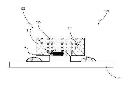
Fig. 3 presents a simplified and magnified view of a LED light source 105
arranged on
an elastic circuit board 102. The LED light source comprises a light-emitting
diode 112
and surrounding it at least in the lateral direction a reflector body 110,
comprising a
reflector surface 111. The reflector body comprises a recess, the side walls
of which
form reflector surfaces. The light-emitting component 112 is disposed in the
recess of
the reflector body 110. The recess is filled at least partly with transparent
protective
material 113 such that the light-emitting diode 112 is at least partly inside
the protective
material. The protective material comprises a material that withstands light
well, more
particularly the light produced by the LED light source and/or UV light,
and/or
temperature without significantly darkening. The protective material 113 is,
according to
the invention, partly or wholly optical aliphatic thermoplastic polyurethane
(aliphatic
TPU).
CA 2825418 2018-05-17
7
According to Fig. 5 on top of the protective material 113 of the light-
emitting diode 112 is
a lens 115, which can be of the same material as or of different material to
the
protective material 113. In one case the outer surface of the lens 115 can be
treated
with a protective material film 116, which is of aliphatic thermoplastic
polyurethane,
.. according to the invention. In this case, it can be conceived that the lens
115 is of
something else, e.g. of silicon. On the other hand, both the protective
material 113 and
the lens 115 can be of the aforementioned aliphatic thermoplastic
polyurethane, in
which case the protective material film 116 is not needed.
Fig. 4 presents yet another embodiment, in which the LED band 101 of Fig. 3 is
surrounded with an envelope part 107. According to one embodiment the envelope
part
107 is wholly or partly of aliphatic thermoplastic polyurethane, which keeps
its clarity
and transparency well, even though a photo effect, such as a UV light effect,
and/or a
thermal effect acts on it. In addition, an envelope part 107 formed from the
material in
question withstands mechanical loads well. The envelope part 107 thus
functions partly
or wholly as a protective material, the clarity of which and/or the
transparency of which
is retained well.
According to the invention optical aliphatic TPU (aliphatic Thermoplastic
Polyurethane)
is thus used, either partly or wholly, as a protective material. This material
has been
used, or is used, e.g. as a thin film, inter alia, between the windshield
glasses of
vehicles or on the outer surface of glass in airplanes. This has been observed
to
possess very good UV durability.
According to one embodiment the material according to the invention is applied
by
extrusion onto the LED band, such as is described e.g. in publication
W09823896 Al in
connection with a conducting tape.
Optical aliphatic thermoplastic polyurethane (TPU) could be used, depending on
the
embodiment, directly on the surface of LEDs (encapsulation or potting), in the
enclosure
to replace silicon. In this case also an elastic structure and better
mechanical properties
are achieved.
CA 2825418 2018-05-17
8
According to one embodiment the material in question, i.e. optical aliphatic
thermoplastic polyurethane, could be a protective coating on top of soldered
components, forming an unbroken layer also on top of silicon lenses.
According to one embodiment the protective material is clear aliphatic
thermoplastic
polyurethane, e.g. of the type Estane ALR E87A. Also other suitable aliphatic
TPU
materials can be used.
An elastic light-source band according to the invention can be manufactured in
a
continuous manufacturing process, such as with an extrusion process, roll-to-
roll.
According to one embodiment the light-emitting diode 112 is more particularly
a diode
emitting blue or white light.
According to one embodiment the light source or light-source band are
emergency exit
luminaires, or are parts thereof, or control luminaires, guidance luminaires
or signaling
luminaires, or are parts thereof.
The invention thus relates to a LED light source 105, which comprises at least
one light-
emitting component 112. The light-emitting component 112 is at least partly
protected
with a transparent protective material 113, which contains aliphatic
thermoplastic
polyurethane (TPU).
According to one embodiment the light-emitting component 112 is arranged in a
recess,
which is at least partly filled with protective material 113.
According to one embodiment the protective material is wholly aliphatic
thermoplastic
polyurethane (TPU).
According to one embodiment the protective material is partly aliphatic
thermoplastic
polyurethane (TPU).
According to one embodiment the protective material film 116 containing
aliphatic
thermoplastic polyurethane TPU is arranged on top of the light-emitting
component 112
and/or the protective material 113 and/or the lens 115.
CA 2825418 2018-05-17
9
According to one embodiment the LED light source 105 is wholly protected with
a
transparent protective material, which contains aliphatic thermoplastic
polyurethane
(TPU).
According to one embodiment the light-emitting diode 112 is more particularly
a diode
emitting blue or white light.
The invention also relates to a light-source band, which comprises light
sources 105,
such as LED light sources, arranged consecutively, which light-source band is
surrounded at least partly with a transparent envelope 107. The light source
105, or at
least the light-emitting component 112 of the light source, is at least partly
protected
with a transparent protective material, which contains aliphatic thermoplastic
polyurethane (TPU).
According to one embodiment the LED light source 105 is wholly protected with
a
transparent envelope 107, which contains aliphatic thermoplastic polyurethane
(TPU).
According to one embodiment the light-source band comprises light sources 105.
According to one embodiment the envelope 107 is a flexible envelope.
It is obvious to the person skilled in the art that the invention is not
limited to the
embodiments presented above, but that it can be varied within the scope of the
claims
presented below. The characteristic features possibly presented in the
description in
conjunction with other characteristic features can also, if necessary, be used
separately
to each other.
CA 2825418 2018-05-17