Note: Descriptions are shown in the official language in which they were submitted.
CA 02825464 2013-07-23
WO 2012/107464 PCT/EP2012/052087
1
APPARATUS FOR KNOTTING DRAWSTRINGS OF MEDICAL DEVICES OR MEDICAL
DEVICES CONTAINING DRUGS
FIELD OF THE INVENTION
The invention relates to methods and apparatuses for making knots in flexible
elements,
particularly in withdrawal cords or strings, pull strings, drawstrings or
positioning strings of
medical devices.
BACKGROUND OF THE INVENTION
It is well-known that devices such as hormonal or copper intra-uterine devices
(IUD), which are
used as a common method of anti-conception and/or for treatment of
menorrhagia, have a
string attached to the device. Similarly, tampons also have a withdrawal cord,
which is affixed to
the tampon by making a knot in said cord. After insertion of a T-shaped IUD,
the string remains
positioned within the cervix for a period of 5 to 10 years to facilitate
extraction of the IUD by the
health care provider. It is customary to provide the string of an IUD with a
knot to securely
fasten the string.
During the history of development of Cu-IUD, specific attention has been
brought on the thread
and on the knot. The Dalkon Shield tails experience in US in the 1970s
established that pelvic
infection (which could ultimately lead to death of the woman) may be
attributed to the
multifilament thread connected to the device. Ever since, the field has been
more cautious
about the details of the string and knot connected to medical devices. More
specifically, the knot
should not hamper the correct insertion of the device, it should not hamper
the efficacy of the
device nor should it have a negative impact on the safety of the device. In
addition, it should be
durable enough to allow for a correct removal of the device after several
years.
The type, the positioning, the resistance, the strength of attachment and the
stability all over the
duration of use of the device may have great impact on the global quality of
the device. The
manufacturing of a device of adequate quality imposes a close control of all
these parameters
and a high reproducibility in the process of making the knot. Typical examples
are the copper-
or hormone (e.g. levonorgestrel) based IUDs. In this case, the length of
string between knot and
IUD is crucial as well as the type and thickness of the knot, because the knot
can block the
delivery of the IUD when e.g. applied through an applicator tube or device.
CA 02825464 2013-07-23
WO 2012/107464 PCT/EP2012/052087
2
Furthermore, the type, the positioning, the resistance and the thickness of
the knot are of crucial
importance for the correct use of the device at the insertion step or at the
removal steps. In
addition, the strength of the attachment of the flexible element to the IUD is
influenced by the
form of the knot.
Finally, the position of the knot with respect to the IUD and its form and
thickness will also be
important to avoid spreading of possible infectious agents such as viruses,
bacteria and fungi
from the vaginal region into the uterus, since it has been observed that said
knot can be the
thriving place of infectious agents (cf. e.g. Roberts et al., 1984,
Contraception 29(3):215-28;
Rivera et al., 1993, Curr Opin Obstet Gynecol 5(6):829-32).
Currently, the flexible elements or wires are mostly tied manually to the
IUDs, because of the
importance to have a reproducible knot at the correct position. A drawback of
presently known
methods for making such knots is that they are too slow and labor-intensive.
Furthermore, they
are prone to human error and batch to batch differences.
Some methods of automating the knot-forming process are known for e.g.
tampons. However,
they are all quite complex. We refer for example to patent US 4,836,587 and US
5,566,435,
describing an apparatus to knot tampon strings using rather complex devices.
The present
invention provides an alternative device and method to make knots in flexible
elements of
medical devices or medical devices containing drugs, which is easy to handle,
cheap and very
effective in positioning and shaping of the knot vis-à-vis the device.
SUMMARY OF THE INVENTION
An object of the invention is to provide a simple and inexpensive apparatus
for making knots in
flexible elements at a high frequency and with a high degree of
predictability.
Another object of the invention is to allow the apparatus to make knots at
different positions of
the flexible element by simple adjustment of only one parameter of the
apparatus.
Another object of the invention is to allow the apparatus to make knots
varying in type and
thickness by simple adjustment of the procedure performed by the apparatus.
CA 02825464 2013-07-23
WO 2012/107464 PCT/EP2012/052087
3
Another object of the invention is to construct and assemble the apparatus in
such a way that it
can be readily automated and integrated into existing production lines for
devices.
The inventors have surprisingly found that these objects can be met either
individually or in any
combination by the apparatus and method according to the invention. The
inventors have also
found that these objects can be met either individually or in any combination
by preferred
embodiments of the apparatus and method according to the invention.
In a preferred embodiment, the invention provides an apparatus (20) for making
a knot in a
flexible element attached to a device, comprising: (i) a guiding means (ABC)
for guiding the
element (2) fixed to the device (1), wherein guiding means (ABC) forms a
geometrical figure
which is large enough to contain the device (1); (ii) a first position (10)
outside the geometrical
figure formed by guiding means (ABC), to which the device (1) can be affixed;
(iii) a second
position (10') to which the device (1) can be affixed, for example after being
lifted over or under
the closed loop(s) to form a relatively loose knot in the element, wherein
said second position
(10') is inside the geometrical figure formed by guiding means (ABC); (iv)
means for tightening
the knot through a tensioning means (40); wherein the guiding means (i), the
first position (ii)
and the second position (iii) can be rotated with respect to the means for
tightening (iv).
In a preferred embodiment, guiding means (ABC) is a single continuous guiding
means, or is
constituted out of several individual guiding means, which can form any
geometrical shape
allowing for the making of a loose loop around the device (1).
In a preferred embodiment of the invention, guiding means (ABC) comprises at
least 3 individual
guiding means parts A, B and C, preferably forming a triangle.
In an alternative embodiment, guiding means (ABC) comprises 2 individual
guiding means parts
A and BC, which together can form any geometrical shape allowing for the
making of a loose
loop.
In a more specific embodiment of the apparatus (20) according to the
invention, the guiding
means (ABC) can be retracted into or lifted away partially or fully from the
apparatus (20) in
CA 02825464 2013-07-23
WO 2012/107464 PCT/EP2012/052087
4
order to release element (2). This can be done in either a single step, in
which all parts of the
guiding means are retracted or lifted at the same time, or in several steps,
wherein each
component of the guiding means is retracted or lifted individually.
In a more specific embodiment, the apparatus (20) according to the invention
additionally
comprises a translating means, capable of translating the device from the
first position (10) to
the second position (10'), by lifting the device over (or under) and inside
the one or more closed
loops formed in the element (2) by the apparatus (20).
In a more specific embodiment of the apparatus (20) according to the
invention, the diameter
and/or the location of part A of the guiding means (ABC), preferably located
closest to the
device (1), with respect to the second position (10') defines the length of
the element between
knot and device.
Alternatively or in combination herewith, the diameter and/or location of the
second position
(10') of the device with respect to the guiding means (ABC), defines the
length of the element
between the knot and the device.
In a more specific embodiment of the apparatus (20) according to the
invention, the one or more
strands of the element (2) are under constant tension, e.g. by means of a
tensioning means
(40).
In a more specific embodiment of the apparatus (20) according to the
invention, one or more
strands of the element are directed towards or away from the guiding means
(ABC) by
tensioning means (40).
In a more specific embodiment of the apparatus (20) according to the
invention, part A of the
guiding means (ABC) is located closest to the end of the device (1) whereon
the element (2) is
fixed.
In a more specific embodiment of the apparatus (20) according to the
invention, the element (2)
is provided to the apparatus (20) in the form of a spindle or bobbin,
preferably capable of
maintaining a certain tension on the element.
CA 02825464 2013-07-23
WO 2012/107464 PCT/EP2012/052087
In another embodiment of the apparatus (20) according to the invention, the
element (2) is
provided to the apparatus (20) already cut beforehand.
In a more specific embodiment of the apparatus (20) according to the
invention, the end of
5 element (2) is held under constant tension by a tensioning means (40).
In a more specific embodiment of the apparatus (20) according to the
invention, all movements
or rotations of the apparatus (20) are automated.
In a more specific embodiment of the apparatus (20) according to the
invention, said translating
means is a robotic arm.
The invention further provides for a method for making a knot in a flexible
element connected to
a device using the apparatus (20) according to the present invention,
comprising the steps of:
a) placing the device (1), to which the element (2) is attached, in the first
position (10) on the
apparatus (20), outside the area defined by guiding means (ABC);
b) the guiding means (ABC) effectuates one or more rotations with respect to
the tensioning
means (40), thereby forming one or more closed loops in element (2);
c) the device (1) is translated from its first position (10) to its second
position (10') inside the
area defined by guiding means (ABC), by lifting it over or under and into the
closed loop(s)
formed in step b);
d) guiding means (ABC) releases the element (2), which is pulled away by
tensioning means
(40), thereby forming the final knot (3).
Preferably, said flexible element is the drawstring of a medical device or a
medical device
containing drugs.
Preferably, the element (2) is cut to a desired length.
In a preferred embodiment of the method according to the invention, the number
of rotations,
translations and threading actions can be adjusted to tailor the thickness of
the knot.
WO 2012/107464 PCT/EP2012/052087
6
In a preferred embodiment of the method according to the invention, said
method is automated.
Preferably, the translation movement of device (1) is performed by a robotic
arm.
In a preferred embodiment of the method according to the invention, guiding
means (ABC)
releases the element in two steps: firstly guiding means BC releases the
element, after which
guiding means A releases the element.
In a preferred embodiment of the method according to the invention, guiding
means (ABC)
releases the element in two or three steps: firstly guiding means B and C
release the element
(either simultaneously or consecutively), after which guiding means A releases
the element.
In a particularly preferred embodiment of the apparatus (20) or method
according to the
invention, the device is an intra uterine device (IUD), for contraceptive or
other intrauterine
treatment, tampons, hearing aids, and the like. In a particularly preferred
embodiment, the
apparatus (20) and methods according to the invention can be used to make a
knot in the
withdrawal cord of a Levonorgestrel secreting contraceptive IUD (cf. Fig. 2).
Although the invention will be described primarily with reference to the
making and manipulation
of strings of intra-uterine devices (IUD) and tampons, the apparatus (20) and
method according
to the present invention can of course be used with equal or similar advantage
for the making of
knots in flexible elements which can be secured to a wide variety of devices.
BRIEF DESCRIPTION OF THE DRAWINGS
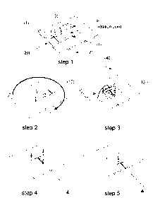
.. Figure 1: Schematic representation of the knot making apparatus and the
method performed
thereby.
DETAILED DESCRIPTION OF THE INVENTION
Unless defined otherwise, all technical and scientific terms used herein have
the same meaning
as is commonly understood by one of skill in the art.
CA 2825464 2018-02-23
CA 02825464 2013-07-23
WO 2012/107464 PCT/EP2012/052087
7
The articles `a' and `an' are used herein to refer to one or to more than one,
i.e. to at least one of
the grammatical object of the article.
Throughout this application, the term `about' is used to indicate that a value
includes the
standard deviation of error for the device or method being employed to
determine the value.
The recitation of numerical ranges by endpoints includes all integer numbers
and, where
appropriate, fractions subsumed within that range (e.g. 1 to 5 can include 1,
2, 3, 4 when
referring to, for example, a number of elements). The recitation of end points
also includes the
end point values themselves (e.g. from 1.0 to 5.0 includes both 1.0 and 5.0)
Throughout this application, the terms `device' or `devices' are used to
denote any object that is
inserted into an external body orifice. Among these devices we consider, but
do not limit
ourselves to: intra-uterine devices (IUD) or intra-uterine systems (IUS),
tampons, hearing aids.
As far as IUD and IUS are concerned, the practical use (e.g. contraceptive,
medicinal), optional
additional components (e.g. antibiotics, antiseptics, hormones) and material
(e.g. copper, silver,
polyethylene) are not deemed critical for this invention.
Throughout this application, the terms 'element' or `elements' are used to
denote any flexible
object that can be knotted. Among these elements we consider, but do not limit
ourselves to:
wires, cables, strings, ribbons, hairs, cords, chains, bands. Furthermore, the
type of material in
which these elements are fabricated is not deemed critical for this invention.
This element can
consist of one or multiple strands. The element may be present on e.g. a
spindle or bobbin or be
already cut beforehand. Said spindle or bobbin should be capable of retaining
a certain amount
of tension on the element.
Throughout this application, the term 'translating means' is used to denote
any part of the
apparatus that can be displaced in a translational fashion. Among these types
of movement we
consider, but do not limit ourselves to: sliding, rolling, dropping.
Furthermore, the type of
material in which these translating means are fabricated is not deemed
critical for this invention.
The translational movement is considered a relative movement between different
parts of the
apparatus, and not referred to a fixed point of reference.
CA 02825464 2013-07-23
WO 2012/107464 PCT/EP2012/052087
8
Throughout this application, the term 'rotation' is used to denote any
relative rotational
movement between different parts of the apparatus, and not referred to a fixed
point of
reference. Among these types of movement we consider, but do not limit
ourselves to: turning,
twisting, spinning.
Throughout this application, the term 'guiding means' is used to denote any
part of the
apparatus that guides the flexible element along a certain element. The
guiding means can form
one geometric shape allowing the making of a loop, or can comprise several
individual guiding
means that together form a geometric shape allowing the making of a loop.
Among these types
of guiding means we consider, but do not limit ourselves to: bolts, hooks,
clamps, arches,
staples, holes, trenches, clasps and elements built therefrom. Furthermore,
the type of material
in which these guiding means are fabricated is not deemed critical for this
invention.
Throughout this application, the term 'tensioning means' is used to denote any
part of the
apparatus that keeps the flexible element under constant tension. Among these
types of
tensioning means we consider, but do not limit ourselves to: coils, springs,
weights, suction
devices. Furthermore, the type of material in which these tensioning means are
fabricated is not
deemed critical for this invention.
Throughout this application, the term 'restraining means' is used to denote
any part of the
apparatus that keeps the translating means restrained to a certain position on
the apparatus.
Among these types of restraining means we consider, but do not limit ourselves
to: studs, pins,
hooks, bolts, clamps, clasps. Furthermore, the type of material in which these
restraining means
are fabricated is not deemed critical for this invention.
Throughout this application, the term 'releasing action' is used to denote any
action that
releases the flexible element from the guiding means. Among these types of
releasing steps we
consider, but do not limit ourselves to: lifting, retracting, sliding off.
Throughout this application, the term 'fixating means' is used to denote any
part of the
apparatus that keeps the device fixed to a certain position. Among these types
of fixating means
we consider, but do not limit ourselves to: studs, pins, hooks, bolts, clamps,
clasps, adhesive
CA 02825464 2013-07-23
WO 2012/107464 PCT/EP2012/052087
9
tape, magnets. Furthermore, the type of material in which these fixating means
are fabricated is
not deemed critical for this invention.
In the following detailed description of the invention, reference is made to
the accompanying
.. drawings that form a part hereof, and in which are shown by way of
illustration only of specific
embodiments in which the invention may be practiced. It is to be understood
that other
embodiments may be utilized and structural or logical changes may be made
without departing
from the scope of the present invention. The following detailed description,
therefore, is not to
be taken in a limiting sense, and the scope of the present invention is
defined by the appended
.. claims.
In one embodiment, the apparatus (20) consists of two settings defined by a
fixating means (10
and 10'), to which a device (1) is secured, while part of the apparatus (20)
provides a rotational
movement. The device is connected to an element (2), which is to be knotted.
The end of the
element (2) (all ends in case of multiple strands) is attached to a tensioning
means (40), which
maintains tension on the string. The apparatus (20) contains a guiding means
(ABC)
surrounding the fixating means (10'). Said guiding means (ABC) is placed in
such a way that the
surface area defined by the guiding means (ABC) is large enough to allow
mechanical threading
of the device (1) through said guiding means (ABC).
In a preferred embodiment of the invention, guiding means (ABC) comprises 3
individual guiding
means A, B and C.
In an alternative embodiment, guiding means (ABC) forms one continuous guiding
means,
which can be any geometrical shape allowing for the making of a loose loop
around device (1).
In an alternative embodiment, guiding means (ABC) comprises 2 individual
guiding means A
and BC, which together can form any geometrical shape allowing for the making
of a loose loop
around device (1).
If applicable, the diameter of part A of the guiding means and its position
with respect to device
(1) can define the position of the knot vis a vis the device (1) and can hence
be optimized
CA 02825464 2013-07-23
WO 2012/107464 PCT/EP2012/052087
according to the preferred position of said knot for a certain application
(i.e. will be dependent
on the type of device).
The fixating means (10') ensure optimal placement of the device (1) and can
serve to fine-tune
5 the position of the knot vis a vis the device. Again, said position can
help in optimizing said
position of the knot for a certain application (i.e. will be dependent on the
type of device).
During the first step (labeled as step 1 in Figure 1), the device (1), to
which the element is
attached (2), is mounted on the fixating means (10). The starting position of
the device (1) is
10 outside the area defined by the guiding means (ABC), and restrained as
such by the fixating
means (10).
In a second step (labeled as step 2 in Figure 1), the apparatus (20)
effectuates one or more
rotations, creating one or more loops of the element (2). The constant tension
of the element (2)
provided by the tensioning means (40) ensures that the loops remain tightened
around the
guiding means (ABC).
In a third step (labeled as step 3 in Figure 1), the device (1) is released
from the fixating means
(10). The device (1) is subsequently re-attached to the second fixating means
(10') from above
the loops. This threading action effectively creates the knot (3).
In a fourth step (labeled as step 4 in Figure 1), the element (2) is released
from the guiding
means B and C (or BC when combined in one means) by a releasing action. This
action
effectively tightens the knot (3) around guiding means A by the tension
provided by the
tensioning means (40). The position of the device (1) vis-a-vis the guiding
means A will define
the length of string between the device and the knot.
In a fifth step (labeled as step 5 in Figure 1), the element (2) is released
from guiding means A
by a releasing action, tightening the final knot (3). The device is
subsequently released from
fixating means (10'). After these steps, the element (2) may be cut to desired
length.
In an alternative embodiment of the invention, the guiding means B and C form
one guiding
means (BC) which undergoes a releasing action in the fourth step.
CA 02825464 2013-07-23
WO 2012/107464 PCT/EP2012/052087
11
In an alternative embodiment of the invention, the guiding means A, B and C
form one guiding
means (ABC), which undergoes a releasing action in the fourth step and does
not require the
fifth step.
The type and thickness of the knot (3) can be varied by the number of
rotations effectuated by
the apparatus (20).
The length of the string between the device and the knot can be accurately
defined by the final
position of the fixating means (10') with respect to guiding means A. This can
be achieved by
either modifying the position of the fixating means (10'), or by modifying the
position of guiding
means A.
The number and positioning of the guiding means can be varied to better
emulate the shape of
the device (1) and ease the threading action. The order during which the
guiding means
undergo a releasing action with respect to the element (2) is not deemed
critical for the
invention. Nevertheless, a final releasing step from guiding means A is the
preferred
embodiment of the invention.
In one embodiment, the apparatus (20) consists of a translating means (10),
which can provide
a translational movement. This translating means (10) contains a setting (11)
to which the
device (1) can be secured. The device is connected to an element (2), which is
to be knotted.
The end of the element (2) (all ends in case of multiple strands) is attached
to a tensioning
means (40), which maintains tension on the string. The apparatus (20) contains
a guiding
means (ABC) adjacent to the translating means (10). Said guiding means (ABC)
is placed in
such a way that the surface area defined by the guiding means is large enough
to allow
mechanical threading of the device (1) through said guiding means (ABC).
The diameter and position of guiding means A will define the position of the
knot vis a vis the
device and can hence be optimized according to the preferred position of said
knot for a certain
application (i.e. will be dependent on the type of device).
CA 02825464 2013-07-23
WO 2012/107464 PCT/EP2012/052087
12
Additional restraining means (50) ensure optimal placement of the translating
means (10) on the
apparatus (20) and can help in fine-tuning the position of the knot vis a vis
the device. Again,
said position can help in optimizing said position of the knot for a certain
application (i.e. will be
dependent on the type of device).
Below, a preferred embodiment of the method according to the invention is
described:
During the first step, the device (1), to which the element is attached (2),
is mounted on the
setting (11) in the translating means (10). The starting position of the
translating means (10)
holding the device (1) is outside the area defined by the guiding means (ABC),
labeled as
position 1 in Figure 1, and restrained as such by the restraining means (50).
In a second step, the apparatus (20) effectuates one or more rotations,
creating one or more
loops of the element (2). The constant tension of the element (2) provided by
the tensioning
means (40) ensures that the loops remain tightened around the guiding means
(ABC).
In a third step, the device (1) is released from the translating means (10).
In a fourth step, the translating means (10), without the device, is moved
under the loops, so
that it is located in the area defined by the guiding means (ABC), and
restrained as such by the
restraining means (50).
In a fifth step, the device (1) is re-attached to the translating means (10)
from above the loops.
This threading action effectively creates the knot (3).
In an optional sixth step, the translating means (10), holding the device (1),
is moved with
respect to guiding means A to define the final length of the element between
the knot (3) and
the device (1), and restrained as such by the restraining means.
In a seventh step, the element (2) is released from the guiding means B and C
by a releasing
action. This action effectively tightens the knot (3) around guiding means A
by the tension
provided by the tensioning means (40).
CA 02825464 2013-07-23
WO 2012/107464 PCT/EP2012/052087
13
In an eighth step, the element (2) is released from guiding means A by a
releasing action,
tightening the final knot (3).
In a final step, the element (2) is cut to desired length and the device (1)
is released from the
translating means (10).
In an alternative embodiment of the invention, the guiding means B and C form
one guiding
means (BC).
In an alternative embodiment of the invention, the guiding means A, B and C
form one guiding
means (ABC), which undergoes a single releasing action in the seventh step and
does not
require the eighth step.
In essence, the invention provides a method for making a knot in a flexible
element connected
to a device using the apparatus (20) according to the invention comprising the
steps of:
a) placing the device (1), to which the element (2) is attached, in the first
position (10) on the
apparatus (20), outside the area defined by guiding means (ABC);
b) rotating the guiding means (ABC) one or more times with respect to the
tensioning means
(40), thereby forming one or more closed loops in element (2);
c) translating the device (1) from its first position (10) to its second
position (10') inside the area
defined by guiding means (ABC), by lifting it over or under the closed loop(s)
formed in step b);
d) releasing element (2) from guiding means (ABC), under constant tension by
the tensioning
means (40), thereby forming the final knot (3).
The type and thickness of the knot (3) can be varied by the number of
rotations effectuated by
the apparatus (20).
The type and thickness of the knot (3) can also be varied by the number of
translations
effectuated by the translating means (10).
The type and thickness of the knot (3) can furthermore be varied by the number
of threading
actions effectuated by release and re-attachment of the device (1) to the
translating means (10).
CA 02825464 2013-07-23
WO 2012/107464 PCT/EP2012/052087
14
The type and thickness of the knot (3) can be varied by any combination of
rotations,
translations and/or threading actions mentioned above in any order and/or
repetition.
The length of the string can be accurately defined by the final position of
the setting (11) on the
translating means (10) with respect to guiding means A. This can be achieved
by either optional
step six, or by modifying the position of guiding means A.
The number and positioning of the guiding means can be varied to better
emulate the shape of
the device (1) and ease the threading action. The order during which the
guiding means
.. undergo a releasing action with respect to the element (2) is not deemed
critical for the
invention. Nevertheless, a final releasing step from guiding means A is the
preferred
embodiment of the invention.
The apparatus (20) of the invention can make knots while one or more ends of
the flexible
elements are already attached to the device. The apparatus (20) of the
invention renders it
possible to make knots in flexible elements each of which consists of two or
more strands.
Examples of certain alternative embodiments according to the invention are
given below.
.. In an embodiment, the invention relates to an apparatus (20) for making a
knot in a flexible
element (2) attached to a medical device (1), which optionally contains a
drug, comprising:
(i) a guiding means (ABC) for guiding the element (2) fixed to the device (1),
wherein guiding
means (ABC) forms a geometrical figure which is large enough to contain the
device (1);
(ii) a first position (10) outside the geometrical figure formed by guiding
means (ABC), to which
the device (1) can be affixed;
(iii) a second position (10') to which the device (1) can be affixed after
being lifted over or under
the closed loop(s) to form a relatively loose knot in the element (2), wherein
said second
position (10') is inside the geometrical figure formed by guiding means (ABC);
(iv) means for tightening the knot through a tensioning means (40);
wherein means (i), (ii) and (iii) can be rotated with respect to means (iv).
In an embodiment, the invention relates to an apparatus (20) as described
above, wherein the
guiding means (ABC) comprises at least three separate guiding means parts, A,
B and C, or
CA 02825464 2013-07-23
WO 2012/107464 PCT/EP2012/052087
comprises two separate guiding means A and BC, forming a geometrical figure
which is large
enough to contain the device (1).
In an embodiment, the invention relates to an apparatus (20) as described
above, additionally
5 comprising a translating means, capable of translating the device from
position 10 to position
10', by lifting the device over or under and inside the one or more closed
loops formed in the
element (2) by the apparatus (20).
In an embodiment, the invention relates to an apparatus (20) as described
above, wherein
10 guiding means (ABC) can be retracted into or lifted away from the
apparatus (20) in order to
release element (2).
In an embodiment, the invention relates to an apparatus (20) as described
above, wherein the
diameter and/or location of part A of the guiding means with respect to
position (10') defines the
15 length of the element between knot and device.
In an embodiment, the invention relates to an apparatus (20) as described
above, wherein one
or more strands of the element are directed towards or away from the guiding
means (ABC) by
tensioning means (40).
In an embodiment, the invention relates to an apparatus (20) as described
above, wherein part
A of the guiding means is located closest to the end of the device (1) whereon
the element (2) is
fixed.
In an embodiment, the invention relates to an apparatus (20) as described
above, wherein the
element (2) is provided to the apparatus in the form of a spindle or bobbin or
already cut,
preferably capable of maintaining a certain tension on the element.
In an embodiment, the invention relates to an apparatus (20) as described
above, wherein all
movements or rotations of the apparatus are automated.
In an embodiment, the invention relates to an apparatus (20) as described
above, wherein said
translation means is a robotic arm.
CA 02825464 2013-07-23
WO 2012/107464 PCT/EP2012/052087
16
In an embodiment, the invention relates to a method for making a knot in a
flexible element
connected to a device using the apparatus (20) according to any one of claims
1 to 10,
comprising the steps of:
a) placing the device (1), to which the element (2) is attached, in the first
position (10) on the
apparatus (20), outside the area defined by guiding means (ABC);
b) rotating the guiding means (ABC) one or more times with respect to the
tensioning means
(40), thereby forming one or more closed loops in element (2);
c) translating the device (1) from its first position (10) to its second
position (10') inside the area
defined by guiding means (ABC), by lifting it over or under the closed loop(s)
formed in step b);
d) releasing element (2) from guiding means (ABC), under constant tension by
the tensioning
means (40), thereby forming the final knot (3).
In an embodiment, the invention relates to a method as described above,
wherein the number of
rotations, translations and threading actions can be adjusted to tailor the
thickness of the knot.
In an embodiment, the invention relates to a method as described above, which
is automated.
In an embodiment, the invention relates to a method as described above,
wherein the
translation movement of device (1) is performed by a robotic arm.
In an embodiment, the invention relates to a method as described above,
wherein the device is
an intra uterine device (IUD), for contraceptive purposes or for intra uterine
treatment, a tampon,
a hearing aid, or the like.