Note: Descriptions are shown in the official language in which they were submitted.
CA 02825817 2013-07-26
WO 2012/107213
PCT/EP2012/000550
1
A PAINT CONTAINER WITH A RELEASABLY SECURED LINER
The present invention relates to a paint container, specifically to a paint
container where
some of the components can be recycled and/or reused.
Typically, paint containers comprise a main body (cylindrical or rectangular
cross section)
made from metal, or plastic, and the paint contained therein is in direct
contact with the
main body. Recycling or re-use of the paint container is made difficult
because the main
body has been contaminated with paint.
This can be overcome by the use of a plastic liner which locates inside the
main body,
and receives the paint, thereby preventing contact between the main body and
the paint.
The contaminated liner is disposed of after use, and the main body can be re-
used/recycled.
The problem with known paint containers comprising liners is the security of
the liner
itself within the paint container.
An object of the present invention is to provide a paint container that
incorporates a liner
that is more secure.
According to the present invention there is provided a paint container
including a main
body, a liner assembly which locates inside the main body, and a shroud, in
which the
shroud cooperates with the liner assembly and the main body so as to
releasably secure
the liner assembly to the main body.
Advantageously, the liner can be releasably secured to the main body, and the
provision
of both a liner assembly and a shroud, i.e. two separate components, enables
easier plastic
moulding when compared to a one-piece construction.
CONFIRMATION COPY
CA 02825817 2013-07-26
WO 2012/107213
PCT/EP2012/000550
2
Preferably the liner assembly is releasably attachable to the shroud which
enables the
non-contaminated shroud to be recycled/re-used, and the contaminated liner
assembly to
be disposed of, thereby decreasing the amount of material to be disposed of.
The invention will now be described with reference to the accompany drawings,
in which:
Figures 1 and 2 are perspective views of a paint container according to the
present
invention,
Figure 3 is a top plan view of the paint container of Figure 1,
Figure 4 is a bottom plan view of the paint container of Figure 1,
Figures 5 to 7 are side views of the paint container of Figure 1,
Figure 8 is a sectional (A-A) perspective view of the paint container of
Figure 1,
Figure 9 is a sectional (A-A) side view of the view of the paint container of
Figure 1,
Figure 10 is a sectional (A-A) perspective view of the paint container of
Figure 1,
Figures 11 to 17 are sectional (A-A) side views and perspective views showing
assembly
of the paint container of Figure 1,
Figure 18 is a sectional (A-A) side view showing part of the paint container
of Figure 1,
Figures 19 to 22 are sectional (A-A) side views and perspective views showing
disassembly of the paint container of Figure 1,
Figures 23 to 25 are perspective views of an alternative paint container,
-
CA 02825817 2013-07-26
WO 2012/107213
PCT/EP2012/000550
3
Figure 26 is a sectional (B-B) view of the paint container of Figure 23,
Figure 27 is a sectional view of an alternative paint container, and
Figure 28 is a plan view of part of the paint container of Figure 27.
Figure 29 is a side sectional view of an alternative paint container.
With reference to Figure 1 there is a shown a paint container 10 comprising a
main body
12, a plastic shroud 14, and a disposable liner assembly 18.
The plastic shroud 14 is attached to a handle 15. It can be seen from Figures
1 and 3 that
the handle 15 is arranged such that (in the closed position ¨ Figures 1 and
3), an outer
periphery is defined by the handle 15 and the plastic shroud 14. The handle 15
is
hingeable attached to the shroud 14 such that it can be moved between a
resting position
(Figure 1) and a carrying position (Figure 2).
The main body 12 is of rectangular construction comprising a front 20, rear
22, left 24,
and right 26 side walls, and a base 28. The main body 12 is constructed of
cardboard,
(often referred to as paperboard) typically comprising multiple layers to
increase rigidity.
It is to be understood that the invention is not limited to cardboard only
main bodies, and
also includes composite structures which include a barrier layer, typically
metallic.
However, the advantage of using a main body constructed cardboard only is the
easier
ability to recycle and/or reuse.
The main body 12 has two through apertures 25 located in each of its four side
walls
(Figure 2 where only two apertures on each of the left and front side walls
are shown).
The shroud 14 is of rectangular construction corresponding to the main body
12, and
includes four sides, left 41, front 43, right 45, and rear 47 (Figure 1) which
are defined by
an outboard downwardly extending portion 17. The downwardly extending portion
17
CA 02825817 2013-07-26
WO 2012/107213
PCT/EP2012/000550
4
has retaining tabs 23 located at its lowermost end, and a downwardly extending
rib 19. In
Figures 1, each of the four sides 41,43,44,45 has two retaining tabs.
The retaining tabs 23, and through apertures 25 are located such that there is
snap fit
engagement therebetween when the shroud 14 is assembled onto the main body 12
(see
below).
In Figures 8 and 9, the liner assembly 18 comprises a plastic liner in the
form of a bag 30,
a plastic neck insert 32 and a lid 34.
The bag 30 has a closed end and an open end 33 so that it can receive and
store liquid
content such as paint.
The neck insert 32 is fixed (typically by welding although other joining
techniques such
as the use of adhesives are envisaged) to the bag 30 at is open end 33. The
neck insert 32
has a similar rectangular plan profile when compared to the main body of the
container
(albeit slightly smaller such that the neck insert fits inside the main body),
and has four
sides corresponding to the main body such that that it can locate on the main
body.
The bag 30 is both shaped and dimensioned such that it can utilise most if not
substantially all of the volume inside the container when filled with paint.
The bag 30 includes a reinforcing ring 40, and a lower ring 90. The lower ring
90
optionally locates into notches 92 in the main body of the container.
The handle 15 locates inside aperture 60 of the shroud 14 and is retained on
the shroud 14
by a snap-fit feature 70 (only shown in Figure 9). It will be appreciated that
when the
container is being held by the handle 15, the weight is transferred to the
shroud 14 and
then to the main body 12 via retaining tabs 23.
CA 02825817 2013-07-26
WO 2012/107213
PCT/EP2012/000550
The neck insert, shroud, handle, and lid are all plastic components, typically
elastomers
suitable for injection molding. A suitable plastic would be Polyethylene, be
that high,
medium or low density.
In an alternative embodiment, both the neck insert and the bag can be moulded
from a
single plastic component thereby negating the need for a joining process.
The container 10 is assembled as follows:
The liner assembly 18 is inserted into the main body 12 of the container 10 by
lowering
neck insert 14 in the direction of arrow Y (Figure 11) until the shoulder 52
on the neck
insert 14 abuts against top surface 54 of the main body 12 of the container 10
(Figure 12).
In Figure 12, the liner assembly 18 is now positioned in the main body 12, but
not yet
securely retained in the vertical direction (arrow Y).
The shroud 14 is lowered in the direction of arrow Y (Figure 13 and 13A) such
that the
downwardly extending rib 19 passes through aperture 21 (only one shown. As the
shroud
14 is lowered further, retaining tab 23 bulges outwards in the direction of
arrow X
(Figure 14 and 14A) by virtue of engagement with the main body 12 and the fact
that the
shroud material is sufficiently thin walled to flex, until the retaining tab
23 snap-fits into
aperture 25 of the main body 14 (Figure 15 and 15A). It is to be understood
that each of
the eight retaining tabs (two on each of the four side walls of the shroud 14)
snap-fit into
each of the eight corresponding apertures 25 on the main body 12 to securely
retained. As
the shroud 14 is lowered onto the main body 12, ribs 50 of the neck insert
compress the
side walls of the main body between the shroud and the neck insert so as to
provide an
interference fit of the side walls between the shroud and the neck insert in
addition to the
snap-fit engagement between the shroud and the main body.
Lid 34 is secured onto liner assembly via snap-fit engagement with neck insert
32 (shown
removed in Figure 16, and secured in Figure 17).
CA 02825817 2013-07-26
WO 2012/107213
PCT/EP2012/000550
6
Figure 18 shows in more detail that there is a vertical separation VLH between
the upper
surface of the lid 34 and the upper surface of the handle 14, and specifically
that the
handle sits vertically above the lid 34. This is advantageous as this allows
the weight of a
similar second container stacked on top to be transmitted and born by the
handle and not
the lid. The stacked second container can have its base adapted in such a way
to
accommodate the protruding handle.
The shroud 14 is removed by inserting a tool such as a screwdriver 60 under
tab 23
(Figure 19 and 19A) and prizing it away from the main body such that a
weakened
section 62 enables the tab 23 to break away from the main body (Figure 20, 20A
and
20B). The tab 23 is no longer biased towards the main body, and the shroud 14
can be
lifted vertically such that it detaches itself from the main body (Figure 21).
The liner assembly 18 can now be removed from the main body 14 since it is no
longer
retained by the shroud (Figure 22).
The liner assembly 18 can be disposed of since it is contaminated with paint.
The plastic shroud 14 can be recycled easily as it is no longer attached to
the liner
assembly 18 or the cardboard main body 14.
The cardboard main body 14 can be recycled easily since it is no longer
attached to the
contaminated liner assembly 18 or the plastic shroud 14.
Thus, the present invention allows both the plastic shroud, and the cardboard
body to be
recycled, and easy disposal of the contaminated liner assembly. This compares
to known
containers where the liner assembly, plastic shroud, and neck insert cannot be
separated,
and therefore more plastic material has to be disposed of.
In the above embodiment, the shroud 14 is separated from the main body by
releasing the
snap-fit between the tab and the notch in the main body. In an alternative
embodiment,
CA 02825817 2013-07-26
WO 2012/107213
PCT/EP2012/000550
7
the main body could include tear bands which are removed such that shroud 14
can be
removed from the main body without the need to mechanically disengage the tab
from
the notch.
With reference to Figure 23 there is shown an alternative container 110
comprising a
main body 112 and a liner assembly 118.
The main body 112 is identical to main body 12 of the embodiment of Figures 1
to 22.
The liner assembly 118 comprises a bag 130 identical to the bag 30 of the
embodiment of
Figures 1 to 22, a plastic neck insert 132, and a lid 134.
The plastic neck insert and bag 130 are welded together.
The lid 132 secures to the plastic neck insert in the same way as in the
embodiment of
Figures 1 to 22.
The plastic neck insert 132 includes an integral handle 115 which includes a
live hinge
170 to enable it to move between the resting (Figure 23) and carrying (Figure
24)
positions. =
In contrast to the embodiment of Figures 1 to 22, the snap-fit tab 123 is
incorporated on
the neck insert 132 as opposed to the shroud, i.e. there is no separate shroud
on container
110. Accordingly, the neck insert 132 and the bag 130 can be assembled onto
and
removed from main body 112 in the same way as in the embodiment of Figures 1
to 22
with the exception that no shroud is required to secure the neck insert (and
hence the liner
assembly) onto the main body.
As in the embodiment of Figures 1 to 22, the handle is arranged such that it
vertically
extends above the lid 134, thereby acting to carry the load of a second
container stacked
above.
CA 02825817 2013-07-26
WO 2012/107213
PCT/EP2012/000550
8
With reference to Figures 27, there is shown an alternative paint container
210 which is
identical to the container of Figures 1 to 22 apart from the modifications
below.
In Figure 27, the neck insert 232 includes a modified downwardly extending rib
219
having a retaining tab 227 at its lower end.
The neck insert 232 includes a substantially horizontally outwardly extending
ledge 229
with apertures 231. Four apertures are positioned on each side of the neck
insert (Figure
28) so that they can engage with the corresponding retaining tabs 227.
The container 210 is assembled in the same way as the container of Figures 1
to 22 with
the exception that downwardly extending rib 219 passes through aperture 231 on
ledge
229 such that the retaining tab 227 snap-fits underneath the ledge 229 to
retain the neck
insert 218 inside the container 10. (Figure 27). The vertical distance Y
between the upper
surface of the ledge 228 and the lower inside surface of the shroud 214 is
shown
exaggerated, whereas in practice this distance would be small, if not zero
(subject to the
manufacturing tolerances) so as to eliminate vertical movement upwardly,
noting that the
downward movement is prevented by the snap-fit engagement between tab 227 and
the
ledge.
Container 210 also includes a modified lid 234
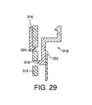
In another embodiment, the neck insert 232 could engage, for example via a
snap-fit
feature, directly with the main body 312 of the paint container so as to
secure the liner
assembly to the paint container. The shroud 314 could then engage (via a snap-
fit for
example) with the main body as described in the previous embodiments via
aperture 325.
Alternatively, the shroud could snap-fit onto the liner assembly by provision
of a
corresponding feature on the liner assembly (not shown), with no requirement
for the
shroud to snap-fit to the main body.