Note: Descriptions are shown in the official language in which they were submitted.
TITLE
COMBINED POWER TAKE-OFF AND HYDRAULIC PUMP ASSEMBLY
[0001]
BACKGROUND OF THE INVENTION
[0002] This invention relates in general to power take-offs for selectively
providing
rotational energy from a source of rotational energy to a driven accessory. In
particular,
this invention relates to an improved structure for a combined power take-off
and
hydraulic pump assembly having a reduced overall length, weight, and number of
parts.
[0003] A power take-off is a well known mechanical device that is often used
in
conjunction with a source of rotational energy, such as a vehicle engine or
transmission,
to provide rotational energy to a driven accessory. For example, power take-
offs are
commonly used in industrial and agricultural vehicles to provide rotational
energy to
hydraulic pumps that, in turn, are used to operate hydraulically driven
accessories such as
plows, trash compactors, lifting mechanisms, winches, and the like. The power
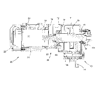
take-off
provides a simple, inexpensive, and convenient means for supplying energy from
the
source of rotational energy to the hydraulic pump that, in turn, provides
relatively high
pressure fluid to operate the driven accessory.
[0004] A typical power take-off includes an input mechanism and an output
mechanism. The input mechanism of the power take-off is adapted to be
connected to the
source of rotational energy so as to be rotatably driven whenever the source
of rotational
energy is operated. The output mechanism of the power take-off is adapted to
be
connected to the hydraulic pump. In some instances, the input mechanism of the
power
1
CA 2825913 2018-05-18
CA 02825913 2013-07-26
WO 2012/109180 PCT/US2012/024061
take-off is directly connected to the output mechanism such that the hydraulic
pump is
rotatably driven whenever the source of rotational energy is operated. In
other instances,
a clutch assembly is provided between the input mechanism and the output
mechanism
such that the hydraulic pump is selectively driven only when the source of
rotational
energy is operated and the clutch assembly is engaged.
[0005] A typical hydraulic pump includes a fluid inlet port, a fluid outlet
port, and a
pumping mechanism. The fluid inlet port is adapted to communicate with a
reservoir
containing a quantity of relatively low pressure hydraulic fluid, while the
fluid outlet port
is adapted to communicate with the hydraulically driven device. The pumping
mechanism of the hydraulic pump is adapted to be connected to the output
mechanism of
the power take-off so as to be rotatably driven whenever the power take-off is
operated.
Thus, when the power take-off is operated, the hydraulic pump draws relatively
low
pressure hydraulic fluid from the reservoir and supplies a flow of relatively
high pressure
hydraulic fluid to the hydraulically driven device.
[0006] The components of the power take-off are typically supported within a
housing
that is closed to retain lubricant and to prevent the entry of dirt, water,
and other
contaminants therein. In many instances, the power take-off housing is formed
from first
and second power take-off housing portions that are separate from one another,
but are
secured together to form a sealed enclosure for the components of the power
take-off.
For example, the first power take-off housing portion may be generally hollow
in shape,
having an opened end and a closed end, while the second power take-off housing
portion
may be generally flat and circular. The second power take-off housing portion
can be
secured to the first power take-off housing portion so as to close the opened
end thereof
and thereby form the power take-off housing. Such a two-piece structure
facilitates the
assembly and servicing of the components of the power take-off, and further
allows either
or both of the input and output mechanisms of the power take-off to be
rotatably
supported on the closed end of the first power take-off housing portion and
the second
power take-off housing portion.
2
CA 02825913 2013-07-26
WO 2012/109180 PCT/US2012/024061
[0007] The components of the hydraulic pump are typically supported within a
housing that is closed to retain hydraulic fluid therein. In many instances,
the hydraulic
pump housing is formed from first and second hydraulic pump housing portions
that are
separate from one another, but are secured together to form a sealed enclosure
for the
components of the hydraulic pump. For example, the first hydraulic pump
housing
portion may be generally hollow and cylindrical in shape, having an opened end
and a
closed end, while the second hydraulic pump housing portion may be generally
flat and
circular. The second hydraulic pump housing portion can be secured to the
first
hydraulic pump housing portion so as to close the opened end thereof and
thereby form
the hydraulic pump housing. Such a two-piece structure facilitates the
assembly and
servicing of the components of the hydraulic pump, and further allows the
components of
the hydraulic pump to be rotatably supported on the first housing portion,
while the input
and output fluid ports are provided in the second hydraulic pump housing
portion.
[0008] Typically, the power take-off and the hydraulic pump have been provided
as
separate, stand-alone devices, each having respective housings that support
and protect
the associated components therein. Thus, to create a combined power take-off
and
hydraulic pump assembly for selectively providing rotational energy from a
source of
rotational energy to a driven accessory, it is known to initially select both
a stand-alone
power take-off and a stand-alone hydraulic pump that are considered to be
appropriate for
the desired application. Then, the housing of the hydraulic pump is mounted on
the
housing of the power take-off to form the combined power take-off and
hydraulic pump
assembly.
[0009] Although the manufacture and assembly of a combined power take-off and
hydraulic pump assembly in this manner has been satisfactory, the need has
arisen to
reduce the overall length, weight, and number of parts of the combined power
take-off
and hydraulic pump assembly. Thus, it would be desirable to provide an
improved
structure for a combined power take-off and hydraulic pump assembly having a
reduced
overall length, weight, and number of parts.
3
CA 02825913 2013-07-26
WO 2012/109180 PCT/US2012/024061
SUMMARY OF THE INVENTION
[0010] This invention relates to an improved structure for a combined power
take-off
and hydraulic pump assembly having a reduced overall length, weight, and
number of
parts. The combined power take-off and hydraulic pump assembly includes a
power
take-off including a housing portion having an opened end and a hydraulic pump
including a housing portion having an opened end. An intermediate housing has
a first
opened end that cooperates with the opened end of the housing portion of the
power take-
off and a second opened end that cooperates with the opened end of the housing
portion
of the hydraulic pump.
[0011] Various aspects of this invention will become apparent to those skilled
in the
art from the following detailed description of the preferred embodiments, when
read in
light of the accompanying drawings.
BRIEF DESCRIPTION OF THE DRAWINGS
[0012] Fig. 1 is a perspective view of a first embodiment of a combined power
take-
off and hydraulic pump assembly in accordance with this invention.
[0013] Fig. 2 is a sectional elevational view of the first embodiment of the
combined
power take-off and hydraulic pump assembly illustrated in Fig. 1.
[0014] Fig. 3 is a sectional elevational view of a second embodiment of a
combined
power take-off and hydraulic pump assembly in accordance with this invention.
[0015] Fig. 4 is a perspective view of a third embodiment of a combined power
take-
off and hydraulic pump assembly in accordance with this invention.
[0016] Fig. 5 is a sectional elevational view of the third embodiment of the
combined
power take-off and hydraulic pump assembly illustrated in Fig. 4.
[0017] Fig. 6 is a perspective view of a fourth embodiment of a combined power
take-
off and hydraulic pump assembly in accordance with this invention.
4
CA 02825913 2013-07-26
WO 2012/109180 PCT/US2012/024061
[0018] Fig. 7 is a sectional elevational view of the fourth embodiment of the
combined
power take-off and hydraulic pump assembly illustrated in Fig. 6.
[0019] Fig. 8 is an enlarged perspective view of an intermediate housing and
bracket
assembly provided between the power take-off and the hydraulic pump in the
fourth
embodiment of the combined power take-off and hydraulic pump assembly
illustrated in
Figs. 6 and 7.
[0020] Fig. 9 are further enlarged view of a pair of brackets used with the
intermediate
housing and bracket assembly illustrated in Fig. 8.
[0021] Fig. 10 is a side elevational view of one of the brackets used with the
housing
and bracket assembly illustrated in Figs. 8 and 9.
[0022] Fig. 11 is a perspective view of a fifth embodiment of a combined power
take-
off and hydraulic pump assembly in accordance with this invention.
[0023] Fig. 12 is a sectional elevational view of the fifth embodiment of the
combined
power take-off and hydraulic pump assembly illustrated in Fig. 11.
DETAILED DESCRIPTION OF THE PREFERRED EMBODIMENTS
[0024] Referring now to the drawings, there is illustrated in Figs. 1 and 2
a first
embodiment of a combined power take-off and hydraulic pump assembly in
accordance
with this invention. The first embodiment of the combined power take-off and
hydraulic
pump assembly includes a power take-off, indicated generally at 10, having a
housing
portion 11. The illustrated housing portion 11 of the power take-off 10 is
generally
hollow in shape, having an opened end 12 and a closed end 13. The housing
portion 11
may have any desired shape. If desired, a portion of the closed end 13 of the
housing
portion 11 may be provided by a removable cap 13a or other similar closure.
[0025] The power take-off 10 includes an input mechanism that is adapted to be
connected to a source of rotational energy so as to be rotatably driven
whenever the
source of rotational energy is operated, as described above. As best shown in
Fig. 2, the
input mechanism of the illustrated power take-off 10 includes an input gear 14
that is
CA 02825913 2013-07-26
WO 2012/109180 PCT/US2012/024061
rotatably supported on an input shaft 14a that, in turn, is supported on the
housing portion
11 of the power take-off 10. It can be seen that the input gear 14 extends
laterally from
the side of the housing portion 11 of the power take-off 10. Thus, the power
take-off 10
is commonly referred to as a "side mount" type of power take-off because it is
typically
mounted on a lateral side of a source of rotational power (such as a
conventional
transmission), as opposed to an axial end thereof.
[0026] The power take-off 10 also includes an output mechanism that is adapted
to be
connected to a driven accessory, as also described above. As also best shown
in Fig. 2,
the output mechanism of the illustrated power take-off 10 includes an output
gear 15 that
keyed or otherwise connected for rotation with an output shaft 16. A first end
(the right
end when viewing Fig. 2) of the output shaft 16 is supported for rotation by
bearings 17
that are, in turn, supported on the closed end 13 of the housing portion 11 of
the power
take-off 10. A second end (the left end when viewing Fig. 2) of the output
shaft 16 is
supported for rotation in a manner that will be described in detail below.
[0027] In the illustrated embodiment, the input gear 14 of the power take-off
10 is
directly connected though the output gear 15 to the output shaft 16 such that
the output
shaft 16 is always driven whenever the source of rotational energy is
operated. However,
if desired, a conventional clutch assembly (not shown) may be provided between
the
input gear 14 and the output shaft 16 such that the output shaft 16 is
selectively driven
only when the source of rotational energy is operated and the clutch assembly
is engaged.
[0028] The first embodiment of the combined power take-off and hydraulic pump
assembly also includes a hydraulic pump, indicated generally at 20, having a
housing
portion 21. The illustrated housing portion 21 of the hydraulic pump 20 is
generally
hollow in shape, having an opened end 22 and a closed end 23. In the
illustrated
embodiment, the housing portion 21 and the closed end 23 of the hydraulic pump
20 are
formed as separate pieces that are secured together, although they may be
formed from a
single piece of material if desired. The housing portion 21 may have any
desired shape.
The housing portion 21 of the hydraulic pump 20 has a fluid inlet port 24
formed therein.
6
CA 02825913 2013-07-26
WO 2012/109180 PCT/US2012/024061
The fluid inlet port 24 is adapted to communicate with a reservoir (not shown)
containing
a quantity of relatively low pressure hydraulic fluid. A pumping mechanism 25
is
provided within the housing 21 of the hydraulic pump 20 and communicates with
the
fluid inlet port 24. The pumping mechanism 25 is connected to the output shaft
16 of the
power take-off 10 so as to be rotatably driven whenever the power take-off 10
is
operated. The pumping mechanism 25 is conventional in the art and may, if
desired, be
embodied as a self-contained pump cartridge that is quickly and easily
interchangeable or
replaceable as a unit. Regardless of the specific structure of the pumping
mechanism 25,
when the power take-off 10 is operated, the hydraulic pump 20 draws relatively
low
pressure hydraulic fluid from the reservoir through the fluid inlet port 24
and supplies a
flow of relatively high pressure hydraulic fluid to the hydraulically driven
device in the
manner in detail described below.
[0029] The first embodiment of the combined power take-off and hydraulic pump
assembly further includes an intermediate housing portion, indicated generally
at 30, that
is provided between the power take-off 10 and the hydraulic pump 20. As best
shown in
Fig. 2, the illustrated intermediate housing portion 30 is generally hollow in
shape,
having a first opened end 31 and a second opened end 32. However, the
intermediate
housing portion 30 may have any desired shape. The first opened end 31 of the
intermediate housing portion 30 is sized and shaped to cooperate with the
opened end 12
of the housing portion 11 of the power take-off 10 so as to provide sealing
engagement
therebetween. To accomplish, conventional flanges, seals, or other structures
may be
provided on or between the first opened end 31 of the intermediate housing
portion 30
and the opened end 12 of the housing portion 11 of the power take-off 10. One
or more
bolts 31a may be used to secure the first opened end 31 of the intermediate
housing
portion 30 to the opened end 12 of the housing portion 11 of the power take-
off 10.
Similarly, the second opened end 32 of the intermediate housing portion 30 is
sized and
shaped to cooperate with the opened end 22 of the housing portion 21 of the
hydraulic
pump 20 so as to provide sealing engagement therebetween. To accomplish,
7
CA 02825913 2013-07-26
WO 2012/109180 PCT/US2012/024061
conventional flanges, seals, or other structures may be provided on or between
the second
opened end 32 of the intermediate housing portion 30 and the opened end 22 of
the
housing portion 21 of the hydraulic pump 20. One or more bolts 32a may be used
to
secure the second opened end 32 of the intermediate housing portion 30 to the
opened
end 22 of the housing portion 21 of the hydraulic pump 20.
[0030] The intermediate housing portion 30 supports a bearing 33 that, in
turn,
rotatably supports the second end (the left end when viewing Fig. 2) of the
output shaft
16 of the power take-off 10. The intermediate housing portion 30 has a fluid
outlet port
34 formed therein. The fluid outlet port 34 is adapted to communicate with the
hydraulically driven device (not shown). The pumping mechanism 25 provided
within
the housing 21 of the hydraulic pump 20 also communicates with the fluid
outlet port 34.
Thus, when the power take-off 10 is operated, the hydraulic pump 20 draws
relatively
low pressure hydraulic fluid from the reservoir and supplies a flow of
relatively high
pressure hydraulic fluid through the fluid outlet port 34 to the hydraulically
driven
device.
[0031] Thus, it can be seen that the intermediate housing portion 30
cooperates with
both the housing portion 11 of the power take-off 10 and the housing portion
21 of the
hydraulic pump 20 to provide an integrated enclosure for the first embodiment
of the
combined power take-off and hydraulic pump assembly. Additionally, the
intermediate
housing portion 30 functionally interacts with each of the power take-off 10
and the
hydraulic pump 20 to reduce the overall length, weight, and number of parts of
the first
embodiment of the combined power take-off and hydraulic pump assembly. This
functional interaction is accomplished by means of both the bearing 33
supported on the
intermediate housing portion 30 and the fluid outlet port 34 formed in the
intermediate
housing portion 30. As discussed above, the bearing 33 rotatably supports the
second end
(the left end when viewing Fig. 2) of the output shaft 16 of the power take-
off 10, while
the fluid outlet port 34 provides communication between the pumping mechanism
25 of
the hydraulic pump 20 and the hydraulically driven device. Thus, the overall
length,
8
CA 02825913 2013-07-26
WO 2012/109180 PCT/US2012/024061
weight, and number of parts of the first embodiment of the combined power take-
off and
hydraulic pump assembly is significantly reduced.
[0032] Fig. 3 illustrates a second embodiment of a combined power take-off and
hydraulic pump assembly in accordance with this invention. The second
embodiment of
the combined power take-off and hydraulic pump assembly includes a power take-
off,
indicated generally at 40, having a housing portion 41. The illustrated
housing portion 41
of the power take-off 40 is generally hollow in shape, having a first opened
end 42 and a
second opened end 43. The housing portion 41 may have any desired shape.
[0033] The power take-off 40 includes an input mechanism that is adapted to be
connected to a source of rotational energy so as to be rotatably driven
whenever the
source of rotational energy is operated, as described above. In the
illustrated
embodiment, the input mechanism of the power take-off 40 includes an input
shaft 44
that is supported on the housing portion 41 of the power take-off 40. It can
be seen that
the input shaft 44 extends axially outwardly from the second opened end 43 of
the
housing portion 41 of the power take-off 40. Thus, the power take-off 40 is
commonly
refeffed to as an "end mount" type of power take-off because it is typically
mounted on
an axial of a source of rotational power (such as a conventional
transmission), as opposed
to a lateral side thereof.
[0034] The power take-off 40 also includes an output mechanism that is adapted
to be
connected to a driven accessory, as also described above. In the illustrated
embodiment,
the output mechanism of the power take-off 40 includes an output gear 45 that
keyed or
otherwise connected for rotation with an output shaft 46. The input shaft 44
is supported
for rotation by bearings 47 that are, in turn, supported on the housing
portion 41 of the
power take-off 40. The output shaft 46 is supported for rotation in a manner
that will be
described in detail below.
[0035] In the illustrated embodiment, the input shaft 44 of the power take-off
10 is
connected though a clutch assembly, indicated generally at 48, to the output
shaft 46.
Thus, the output shaft 46 is rotatably driven only when the source of
rotational energy is
9
CA 02825913 2013-07-26
WO 2012/109180 PCT/US2012/024061
operated and the clutch assembly 48 is engaged. However, if desired, the input
shaft 44
of the power take-off 10 may be directly to the output shaft 46 such that the
output shaft
46 is always driven whenever the source of rotational energy is operated.
[0036] The second embodiment of the combined power take-off and hydraulic pump
assembly also includes a hydraulic pump, indicated generally at 50, having a
housing
portion 51. The illustrated housing portion 51 of the hydraulic pump 50 is
generally
hollow in shape, having an opened end 52 and a closed end 53. In the
illustrated
embodiment, the housing portion 51 and the closed end 53 of the hydraulic pump
50 are
formed from a single piece of material, although they may be formed as
separate pieces
that are secured together if desired. The housing portion 51 may have any
desired shape.
The housing portion 51 of the hydraulic pump 50 has a fluid inlet port 54
formed therein.
The fluid inlet port 54 is adapted to communicate with a reservoir (not shown)
containing
a quantity of relatively low pressure hydraulic fluid. A pumping mechanism 55
is
provided within the housing 51 of the hydraulic pump 50 and communicates with
the
fluid inlet port 54. The pumping mechanism 55 is connected to the output shaft
46 of the
power take-off 40 so as to be rotatably driven whenever the power take-off 40
is operated
and the clutch assembly 48 is engaged. The pumping mechanism 55 is
conventional in
the art and may, if desired, be embodied as a self-contained pump cartridge
that is
quickly and easily interchangeable or replaceable as a unit. Regardless of the
specific
structure of the pumping mechanism 55, when the power take-off 10 is operated
and the
clutch assembly 48 is engaged, the hydraulic pump 50 draws relatively low
pressure
hydraulic fluid from the reservoir through the fluid inlet port 54 and
supplies a flow of
relatively high pressure hydraulic fluid to the hydraulically driven device in
the manner
in detail described below.
[0037] The second embodiment of the combined power take-off and hydraulic pump
assembly further includes an intermediate housing portion, indicated generally
at 60, that
is provided between the power take-off 40 and the hydraulic pump 50. In the
illustrated
embodiment, the intermediate housing portion 60 is generally hollow in shape,
having a
CA 02825913 2013-07-26
WO 2012/109180 PCT/US2012/024061
first opened end 61 and a second opened end 62. However, the intermediate
housing
portion 60 may have any desired shape. The first opened end 61 of the
intermediate
housing portion 60 is sized and shaped to cooperate with the first opened end
42 of the
housing portion 41 of the power take-off 40 so as to provide sealing
engagement
therebetween. To accomplish, conventional flanges, seals, or other structures
may be
provided on or between the first opened end 61 of the intermediate housing
portion 60
and the first opened end 42 of the housing portion 41 of the power take-off
40. One or
more bolts (not shown) may be used to secure the first opened end 61 of the
intermediate
housing portion 60 to the first opened end 42 of the housing portion 41 of the
power take-
off 40. Similarly, the second opened end 62 of the intermediate housing
portion 60 is
sized and shaped to cooperate with the opened end 52 of the housing portion 51
of the
hydraulic pump 50 so as to provide sealing engagement therebetween. To
accomplish,
conventional flanges, seals, or other structures may be provided on or between
the second
opened end 62 of the intermediate housing portion 60 and the opened end 52 of
the
housing portion 51 of the hydraulic pump 50. One or more bolts (not shown) may
be
used to secure the second opened end 62 of the intermediate housing portion 60
to the
opened end 52 of the housing portion 51 of the hydraulic pump 50.
[0038] The intermediate housing portion 60 supports a bearing 63 that, in
turn,
rotatably supports the output shaft 46 of the power take-off 40. The
intermediate housing
portion 60 has a fluid outlet port 64 formed therein. The fluid outlet port 64
is adapted to
communicate with the hydraulically driven device (not shown). The pumping
mechanism 55 provided within the housing 51 of the hydraulic pump 50 also
communicates with the fluid outlet port 64. Thus, when the power take-off 40
is operated
and the clutch assembly 48 is engaged, the hydraulic pump 50 draws relatively
low
pressure hydraulic fluid from the reservoir and supplies a flow of relatively
high pressure
hydraulic fluid through the fluid outlet port 64 to the hydraulically driven
device.
[0039] Thus, similar to the first embodiment of the combined power take-off
and
hydraulic pump assembly, the intermediate housing portion 60 cooperates with
both the
11
CA 02825913 2013-07-26
WO 2012/109180 PCT/US2012/024061
housing portion 41 of the power take-off 40 and the housing portion 51 of the
hydraulic
pump 50 to provide an integrated enclosure for the second embodiment of the
combined
power take-off and hydraulic pump assembly. Additionally, the intermediate
housing
portion 60 functions with each of the power take-off 40 and the hydraulic pump
50 to
reduce the overall length, weight, and number of parts of the second
embodiment of the
combined power take-off and hydraulic pump assembly.
[0040] Figs. 4 and 5 illustrate a third embodiment of a combined power take-
off and
hydraulic pump assembly in accordance with this invention. The third
embodiment of
the combined power take-off and hydraulic pump assembly is similar to the
first
embodiment illustrated in Figs. 1 and 2, and like reference numbers
(incremented by 100)
are used to indicate similar components. In the third embodiment, however, the
housing
portion 121 of the hydraulic pump 120 and the intermediate housing portion 130
are
formed from a single piece of material, rather than from separate pieces of
material as in
the first embodiment. Otherwise, the structure and operation of the third
embodiment of
a combined power take-off and hydraulic pump assembly are the same as
described
above in connection with the first embodiment. Similarly, it will be
appreciated that the
housing portion 51 of the hydraulic pump 50 and the intermediate housing
portion 60 of
the second embodiment of the combined power take-off and hydraulic pump
assembly
illustrated in Fig. 3 may also be formed from a single piece of material,
rather than from
separate pieces of material.
[0041] Figs. 6 and 7 illustrate a fourth embodiment of a combined power take-
off and
hydraulic pump assembly in accordance with this invention. The fourth
embodiment of
the combined power take-off and hydraulic pump assembly is also similar to the
first
embodiment illustrated in Figs. 1 and 2, and like reference numbers
(incremented by 200)
are used to indicate similar components. In the fourth embodiment, however,
the
hydraulic pump 220 and the intermediate housing 230 can be positioned as a
unit at any
desired rotational orientation relative to the power take-off 210 and secured
thereto. This
can be accomplished by providing a mounting structure for the intermediate
housing 230.
12
CA 02825913 2013-07-26
WO 2012/109180 PCT/US2012/024061
As best shown in Fig. 8, the intermediate housing 230 has an annular groove
235 formed
in the outer surface thereof adjacent to the first opened end 231 thereof.
First and second
clamping brackets 236 and 237 extend within the annular groove 235 to allow
the
intermediate housing 230 (and the hydraulic pump 220 secured thereto) to be
positioned
at any desired rotational orientation relative to the power take-off 210 and
secured
thereto.
[0042] The structure of the first and second clamping brackets 236 and 237 is
best
illustrated in Figs. 9 and 10. As shown therein, the first and second clamping
brackets
236 and 237 have respective inner surfaces 236a and 237a that are preferably
sized and
shaped to fit within the annular groove 235 so as to be circumferentially
slidable relative
to the intermediate housing 230, while permitting only a minimum amount of
relative
axial movement therebetween. Each of the first and second clamping brackets
236 and
237 also has one or more apertures 236b and 237b, respectively, formed
therethrough for
a purpose that will be explained below. Lastly, the first and second clamping
brackets
236 and 237 may further have respective enlarged thickness regions 236c and
237c
provided therein, again for a purpose that will be explained below.
[0043] To install the intermediate housing 230 on the power take-off 210, the
first
opened end 231 of the intermediate housing 230 is positioned adjacent to the
opened end
211 of the power take-off 210 at a desired rotational orientation relative
thereto. When
the desired relative rotational orientation has been achieved, the first and
second
clamping brackets 236 and 237 are disposed such that the inner surfaces 236a
and 237a
thereof engage the outer surface of the annular groove 235, as best shown in
Fig. 8. The
apertures 236b and 237b respectively formed through the first and second
clamping
brackets 236 and 237 are aligned with corresponding threaded bores (not shown)
formed
in the housing 211 of the power take-off 220, thereby allowing bolts 238 to be
inserted
therethrough to secure the intermediate housing 230 (and the hydraulic pump
220 secured
thereto) to the power take-off 210 at the desired relative rotational
orientation. The
enlarged thickness regions 236c and 237c are preferably sized such that when
the first
13
CA 02825913 2013-07-26
WO 2012/109180 PCT/US2012/024061
and second clamping brackets 236 and 237 are installed into the annular groove
235, they
are generally flush with the opened end 231 of the intermediate housing 230,
as shown in
Fig. 8. As a result, the axial forces generated by the tightening of the bolts
238 are
prevented from damaging either the opened end 231 of the intermediate housing
230 or
the first and second clamping brackets 236 and 237.
[0044] Figs. 11 and 12 illustrate a fifth embodiment of a combined power take-
off and
hydraulic pump assembly in accordance with this invention. The fifth
embodiment of the
combined power take-off and hydraulic pump assembly is similar to the third
embodiment illustrated in Figs. 4 and 5, and like reference numbers
(incremented by 200)
are used to indicate similar components. In the fifth embodiment, however, the
hydraulic
pump 320 and the intermediate housing 330 can be positioned as a unit at any
desired
rotational orientation relative to the power take-off 310 and secured thereto.
This can be
accomplished by providing a mounting structure for the intermediate housing
330 that is
similar to the intermediate housing 230 described above in connection with the
fourth
embodiment of the combined power take-off and hydraulic pump assembly and
illustrated in Figs. 6 through 10. Thus, the intermediate housing 330 has an
annular
groove 335 formed in the outer surface thereof adjacent to the first opened
end 331
thereof. First and second clamping brackets 336 and 337 extend within the
annular
groove 335 to allow the intermediate housing 330 (and the hydraulic pump 320
secured
thereto) to be positioned at any desired rotational orientation relative to
the power take-
off 310 and secured thereto.
[0045] The principle and mode of operation of this invention have been
explained and
illustrated in its preferred embodiments. However, it must be understood that
this
invention may be practiced otherwise than as specifically explained and
illustrated
without departing from its spirit or scope.
14