Note: Descriptions are shown in the official language in which they were submitted.
DOUBLE HELIX CONDUCTOR
FIELD OF THE INVENTION
(01) The invention relates to bodies structured as helically wound runners
around
which one or more conductive wires may be wound, electrical devices and/or
systems configured to include such bodies, and the manufacture of such bodies
and/or such electrical devices and/or systems. The invention also relates to
methods of operation of these devices and systems, and applications thereof.
BACKGROUND OF THE INVENTION
(02) It is known that spirally wound electrical conductors may exhibit certain
electromagnetic properties and/or generate particular electromagnetic fields.
For
example, it is known that an electromagnetic coil may act as an inductor
and/or part
of a transformer, and has many established useful applications in electrical
circuits.
An electromagnetic coil may be used to exploit the electromagnetic field that
is
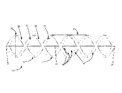
created when, e.g., an active current source is operatively coupled to both
ends of
the coil.
SUMMARY
(03) One aspect of the invention relates to an electrical system comprising a
body
and one or more conductive wires. The body may include two intertwined
helically
wound runners. A first runner is coupled to the second runner by struts. The
body is
arranged in a toroidal shape. The one or more conductive wires may be spirally
wound around at least one runner of the body.
(04) These and other objects, features, and characteristics of the present
disclosure, as well as the methods of operation and functions of the related
components of structure and the combination of parts and economies of
manufacture, will become more apparent upon consideration of the following
description and the appended claims with reference to the accompanying
drawings,
all of which form a part of this specification, wherein like reference
numerals
designate corresponding parts in the various figures. It is
to be expressly
1
CA 2826408 2018-03-23
understood, however, that the drawings are for the purpose of illustration and
description only and are not intended as a definition of the any limits. As
used in the
specification and in the claims, the singular form of "a", "an", and "the"
include plural
referents unless the context clearly dictates otherwise.
BRIEF DESCRIPTION OF THE DRAWINGS
(05) FIG. 1 illustrates a side view of an exemplary body including two
intertwined
helically wound runners, coupled by struts.
(06) FIG. 2 illustrates an isometric view of an exemplary body including two
intertwined helically wound runners, coupled by struts.
(07) FIG. 3 illustrates a top-down view of an exemplary body including two
intertwined helically wound runners sharing the same circular axis, both
runners
coupled by struts.
(08) FIG. 4 illustrates an isometric view of an exemplary body including two
intertwined helically wound runners sharing the same circular axis, both
runners
coupled by struts.
(09) FIG. 5 illustrates a top-down view of an exemplary body including two
intertwined helically wound runners sharing the same circular axis and having
wire
guides, both runners coupled by struts.
(10) FIG. 6 illustrates an isometric view of an exemplary body including two
intertwined helically wound runners sharing the same circular axis and having
wire
guides, both runner coupled by struts.
(11) FIG. 7 illustrates a top-down view of an exemplary body including two
intertwined helically wound runners sharing the same elliptical axis, both
runner
coupled by struts.
(12) FIG. 8 illustrates a top-down view of an exemplary body including two
intertwined helically wound runners sharing the same circular axis, both
runners
coupled by struts and having conductive wires spirally wound therearound.
2
CA 2826408 2018-03-23
(/3) FIG. 9 illustrates a top-down view of an exemplary body including two
intertwined helically wound runners sharing the same circular axis, both
runner
coupled by struts and having a wire spirally wound around both runners of the
body.
DETAILED DESCRIPTION
(14) FIG. 1 illustrates a side view of an exemplary body 15. Body 15 may
include
two or more intertwined helically wound runners ¨ runner 16 and runner 17.
Runner
16 and runner 17 may be coupled by struts 18. Body 15 includes two ends ¨ end
20
and end 21 ¨ disposed at opposite sides of body 15. Runners 16 and/or 17 may
be
arranged in the shape of a three-dimensional curve similar to or substantially
the
same as a helix. A helix may be characterized by the fact that a tangent line
at any
point along the curve has a constant angle with a (fixed) line called the
axis. The
pitch of a helix may be the width of one 360 degree helix turn (a.k.a.
revolution), e.g.
measured parallel to the axis of the helix. Intertwined helically wound
runners may
share the same axis, be congruent, and/or differ by a translation along the
axis, e.g.
measuring half the pitch. The two runners shown in FIG. 1 may share the same
axis
22, extending horizontally for approximately three complete revolutions. The
length
of body 15, as measured along axis 22 from end 20 to end 21, may thus be
approximately three times the length of pitch 23. A helical shape may have
constant
pitch, constant radius (measured in the plane perpendicular to the axis),
constant
torsion, constant curvature, constant ratio of curvature to torsion, and/or a
straight
axis. In FIG. 1, the radius of body 15 may be half of diameter 24. It is noted
that the
shape of body 15 resembles the general shape of DNA.
(15) The shape of the cross-section of a runner may include one or more of a
circle, an oval, a square, a triangle, a rectangle, an angular shape, a
polygon, and/or
other shapes. The width and height of the cross-section of a runner may be
limited
to a maximum of half the pitch for practical purposes. The shape and/or size
of the
cross-section of a runner may change along the length of the runner. The
relation of
the width of a runner to the pitch of the helical shape may define a
characteristic
measurement/feature of body 15. This relation may be constant along the length
of
body 15, e.g. from end 20 to end 21. In FIG. 1, the shape of cross-section of
runner
3
CA 2826408 2018-03-23
16 and runner 17 may be a rectangle that is approximately three times wider
than it
is tall. Furthermore, the width of runner 16 or runner 17 may be approximately
1/13th of the pitch of said runner of body 15. As a result, runner 17 of body
15
resembles a ribbon having an inner surface 25 (facing axis 22 of the helical
shape)
and an outer surface 26 (facing the opposite way as inner surface 25). Runner
16 of
body 15 resembles a ribbon having an inner surface 27 (facing axis 22 of the
helical
shape) and an outer surface 28 (facing the opposite way as inner surface 27).
(16) Struts 18 coupling the runner 16 and runner 17 may be substantially
straight,
curved, the shape of an arc, twisted, and/or other shapes. In FIG. 1, struts
18 may
be substantially straight. Struts 18 may be arranged substantially
perpendicular to
axis 22, and/or substantially parallel to others of struts 18. The shape of a
cross-
section of a strut may include one or more of a circle, an oval, a square, a
triangle, a
rectangle, an angular shape, a polygon, and/or other shapes. The shape and/or
size
of the cross-section of one of struts 18 may change along the length of the
strut. In
FIG. 1, the shape of the cross-section of struts 18 may be a circle. In FIG.
1, all or
most struts may have substantially the same length. The number of struts per
revolution may not be constant. In FIG. 1, body 15 includes approximately 10
struts
per complete revolution of a runner. As shown in FIG. 1, the diameter of each
strut
may be smaller than the width of a runner as measured e.g. at inner surface 25
of
runner 17 at the point of engagement 19 with one of struts 18. The diameter of
one
strut may not be constant. The diameters of multiple adjacent struts may not
be the
same.
(17) Runner 16, runner 17 and/or struts 18 may be manufactured from one or
more of plastic, plastic plated with metals including copper, nickel, iron,
soft iron,
nickel alloys, and/or other metals and alloys, and/or other materials. In some
embodiments, runner 16, runner 17 and struts 18 are manufactured from non-
conductive material. Runner 16, runner 17, and struts 18 may be manufactured
from different materials. Runner 16, runner 17, and struts 18 may be
manufactured
through integral construction or formed separately prior to being assembled.
4
CA 2826408 2018-03-23
(18) FIG. 2 illustrates an isometric view of an exemplary body 15 including
two
intertwined helically wound runners ¨ runner 16 and runner 17 ¨ coupled by
struts
18. Body 15 is shown here with axis 22 of both helically wound runners
extending
vertically.
(/9) FIG. 3 illustrates a top-down view of an exemplary body 35 including two
intertwined helically wound runners ¨ runner 36 and runner 37 ¨ sharing the
same
circular axis 42, both runners coupled by struts 38. The resulting shape of
body 35
may be referred to as toroidal. Body 35 may be formed the same as or similar
to
body 15, though comprising more revolutions, by arranging the body in a planar
circular shape and joining both ends ¨ end 20 and end 21 in FIG. 1 ¨ together.
The
preceding statement is not intended to limit the (process of) manufacture of
bodies
similar to or substantially the same as body 35 in any way. Note that the
shape of
the cross-section of both runner 36 and runner 37 in FIG. 3 may be circular,
whereas
it may be rectangular for body 15 in FIGs. 1 and 2.
(20) Referring to FIG. 3, the diameter 44 of the circular axis of body 35, as
well as
the number of complete revolutions per runner required to completely extend
along
the entire circular axis 42 may be characteristic measurements/features of
body 35.
For example, as shown in FIG. 3, runner 36 and runner 37 of body 35 may
require
approximately eight complete revolutions around circular axis 42 to completely
extend along the entire circular axis 42 of body 35, or some other number of
rotations.
(2/) Note that one or more struts 38 of body 35 in FIG. 3 include a center-
strut
element 39, which is lacking from struts 18 of body 15. Center-strut element
39 may
be associated with a particular strut of body 35. The shape of the cross
section of a
center-strut element may include one or more of a circle, an oval, a square, a
triangle, a rectangle, an angular shape, a polygon, and/or other shapes. The
shape
and/or size of the cross-section of one of center-strut elements 39 may change
along the length of center-strut element 39. One or more struts 38 of body 35
may
include a center-strut element 39, which may have a different shape than a
center-
strut element 39 of another one of struts 38. In FIG. 3, the shape of the
cross-
CA 2826408 2018-03-23
section of center-strut element 39 may be circular, such that center-strut
element 39
may have a cylindrical shape, in which the axis of the cylindrical shape of a
given
center-strut element 39 may coincide with the associated strut 38. In FIG. 3,
struts
38 include center-strut element 39, having substantially the same shape. A
center-
strut element may enhance structural integrity and/or serve other purposes.
(22) FIG. 4 illustrates an isometric view of an exemplary body 35 including
two
intertwined helically wound runners ¨ runner 36 and runner 37 ¨ sharing the
same
circular axis, both runners coupled by struts 38. Note that, as in FIG. 3, the
struts of
body 35 in FIG. 4 may include a center-strut element 39, which may be lacking
from
struts 18 of body 15.
(23) FIG. 5 illustrates a top-down view of an exemplary body 55 including two
intertwined helically wound runners ¨ runner 57 and runner 58 ¨ sharing the
same
circular axis 62 and having wire guides 56, both runners coupled by struts 59.
Though the shape of the cross-section of runner 57 and runner 58 in FIG. 5 may
be
circular, a runner may still have an inner surface (the half of the surface of
a runner
for which normal vectors are directed approximately inward toward body 55) and
an
outer surface (the half of the surface of a runner for which normal vectors
are
directed approximately outward, away from body 55). Any part of runner 57 or
runner 58 may include wire guides 56. Wire guides 56 may include grooves,
notches, protrusions, slots, and/or other structural elements disposed on
and/or in
runner 57 or runner 58 and configured to guide a wire along at least a part of
the
surface of runner 57 or runner 58, generally in a direction substantially
perpendicular
to the direction of runner 57 or runner 58 at the point of engagement between
one of
wire guides 56 and runner 57 or runner 58.
(24) In FIG. 5, one of wire guides 56 of runner 58 may include a protrusion
disposed on the outer surface of runner 58, arranged such that wire guide 56
may
guide a wire arranged in a helical shape around runner 58, wherein the helical
shape
has an axis that coincides with runner 58. Such a wire, as any wire listed in
any
figure included in this description, may be insulated, uninsulated, or
partially
insulated and partially uninsulated. As shown in FIG. 5, wire guides 56 may be
6
CA 2826408 2018-03-23
disposed in an intermittent pattern rather than a continuous pattern, e.g.
such that no
protrusion is disposed on the surface of runner 57 or runner 58 approximately
nearest to (or directly opposite to) one of points of engagement 63 between
runner
57 or runner 58 and of one struts 59. The number of wire guides per complete
revolution of a runner and/or the number of wire guides between adjacent
struts may
be characteristic measurements/features of body 55. The size, shape, position,
and/or pattern of disposition of wire guides 56 may be characteristic
measurements/features of body 55.
(25) FIG. 6 illustrates an isometric view of an exemplary body 55 including
two
intertwined helically wound runners ¨ runner 57 and runner 58 ¨ sharing the
same
circular axis and having wire guides 56, both runners coupled by struts 59.
(26) FIG. 7 illustrates a top-down view of an exemplary body 75 including two
intertwined helically wound runners ¨ runner 76 and runner 77 ¨ sharing the
same
elliptical axis 78, both runner coupled by struts 79. A body including two (or
more)
intertwined helically wound runners sharing the same axis may be arranged in
any
planar shape, including a circle, an oval, a triangle, a square, a rectangle,
an angular
shape, a polygon, and/or other planar shapes. Alternatively, and/or
simultaneously,
such a body may be arranged in a three-dimensional curve (a.k.a. space curve).
In
FIG. 7, body 75 may be formed from a body similar to body 15, though
comprising
more revolutions, by arranging the body in an planar elliptical shape and
joining both
ends ¨ end 20 and end 21 in FIG. 1 ¨ together. The preceding statement is not
intended to limit the (process of) manufacture of bodies similar to or
substantially the
same as body 75 in any way.
(27) FIG. 8 illustrates a top-down view of an exemplary body 85 including two
intertwined helically wound runners ¨ runner 88 and runner 89 ¨ sharing the
same
circular axis, coupled by struts 90 and having conductive wires - wire 86 and
wire 87
- spirally wound therearound. Wire 86 and wire 87, as any wire listed in any
figure
included in this description, may be insulated, uninsulated, or partially
insulated and
partially uninsulated. The shape of body 85 may be similar to the shape of
body 35
in FIG. 3. Runner 88 and runner 89 of body 85 may form cores around which wire
7
CA 2826408 2018-03-23
86 and wire 87 are spirally wound, respectively. As such, wire 86 and wire 87
may
be arranged in a helical shape having axes that coincide with runner 88 and
runner
89, respectively. As shown in FIG. 8, wire 86 and 87 may be wound such that
they
go around any of struts 90 of body 85 and/or around any points of engagement
between one of struts 90 and one of runners 88 and 89. The number of wire
turns
per complete revolution of a runner and/or the number of wire turns between
adjacent struts may be characteristic measurements/features of body 85. In
FIG. 8,
wire 86 and wire 87 may be arranged to make approximately five turns between
adjacent struts associated with runner 88 and runner 89, respectively, and/or
some
other number of turns.
(28) Wire 86 may include two leads ¨ lead 86a and lead 86b. Wire 87 may
include
two leads ¨ lead 87a and lead 87b. Wire 86 and wire 87 may be conductive. Body
85 may be used in an electrical system having one or more power sources and/or
current sources arranged such that electrical coupling with one or both of
wire 86
and wire 87 may be established, e.g. through coupling with lead 86a and 86b of
wire
86 and through coupling with lead 87a and 87b of wire 87. The current supplied
to
wire 86 may be a direct current or an alternating current. The current
supplied to
wire 87 may be a direct current or an alternating current. The currents
supplied to
wire 86 and wire 87 may flow in the same direction or the opposite direction.
For
alternating currents, operating frequencies ranging from 0 Hz to 40 GHz are
contemplated. The operating frequencies for wire 86 and wire 87 may be the
same
or different. Other electrical operating characteristics of current supplied
to wire 86
and wire 87, such as phase, may be the same or different. The electrical
system
may be used to exploit the electromagnetic field that is created when
electrical
power is supplied to one or more wires of body 85.
(29) Some embodiments of an electrical system including a body similar to or
substantially the same as body 85 in FIG. 8, thus including wire 86 and wire
87, may
be configured to have a current in wire 86 flowing in the opposite direction
as the
current in wire 87. In some embodiments the current supplied to one wire may
be a
direct current, whereas the current supplied to another wire may be an
alternating
current.
8
CA 2826408 2018-03-23
(30) FIG. 9 illustrates a top-down view of an exemplary body 95 including two
intertwined helically wound runners ¨ runner 97 and runner 98 ¨ sharing the
same
circular axis, both runner coupled by struts and having a wire 96 spirally
wound
around both runners of body 95. Wire 96, as any wire listed in any figure
included in
this description, may be insulated, uninsulated, or partially insulated and
partially
uninsulated. Wire 96 may include two leads ¨ lead 86a and lead 86b. The
resulting
shape of body 95 with wire 96 may be referred to as a helicoidal shape. Wire
96
may be conductive. Body 95 may be used in an electrical system having a power
source and/or a current source arranged such that electrical coupling with
wire 96,
e.g. through leads 96a and 96b, may be established. The electrical power
supplied
to wire 96 may include a direct current or an alternating current. Operating
frequencies for an alternating current flowing through wire 96 are
contemplated to
range from 0 Hz to 40 GHz. The electrical system may be used to exploit the
electromagnetic field that is created when electrical power is supplied to
wire 96 of
body 95.
(31) Any of the bodies shown in figures 1-9 may be used in an electrical
system.
Conductive wires may be spirally wound around one or more runners, one or more
struts, and/or any combination thereof to produce electrical systems having
specific
electromagnetic properties when electrical power is supplied to one or more of
the
conductive wires. These conductive wires may be insulated, uninsulated, or
partially
insulated and partially uninsulated. A (magnetic) core may be disposed in the
space
between multiple runners, such that the runners helically wound around the
(magnetic) core. Alternatively, and/or simultaneously, relative to any body
described
herein, a (magnetic) core may be moved along a straight line, along any curve
of the
body, along a strut, along a runner, along any axis of the body, or along any
surface
of the body, in any three-dimensional relation to the body. For example, a
magnet
may be moved along a line perpendicular to the planar shape of body 85, in the
center of the circular axis of body 85, a.k.a. through the "donut-hole."
(32) Applications for any of the electrical systems described herein may
include
affecting growth and/or growth rate of plants and/or other organisms.
Applications
for any of the electrical systems described herein may include therapeutic
9
CA 2826408 2018-03-23
applications. Applications for any of the electrical systems described herein
may
include energy production, conversion, and/or transformation. Applications for
any
of the electrical systems described herein may include ATP production,
transfer,
and/or processing.
(33) In some embodiments, an electrical system including any of the bodies
shown
in figures 1-9 may be used as a component in an electrical circuit, performing
one or
more functions and/or applications including a (tunable) inductor, a (Tesla)
coil, a
transformer, a transducer, a transistor, a resistor, a solenoid, a stator for
an electrical
motor, an electromagnet, an electromagnetic pulse generator, an
electromagnetic
actuator, an energy conversion device, a position servomechanism, a generator,
a
stepping motor, a DC motor, a (contact-free) linear drive, an axial flux
device, a
measurement device for magnetic permeability, a dipole magnet, and a device to
alter electron and/or particle trajectory.
(34) Although the invention has been described in detail for the purpose of
illustration based on what is currently considered to be the most practical
and
preferred embodiments, it is to be understood that such detail is solely for
that
purpose and that the invention is not limited to the disclosed embodiments,
but, on
the contrary, is intended to cover modifications and equivalent arrangements
that
are within the spirit and scope of the appended claims. For example, it is to
be
understood that the present invention contemplates that, to the extent
possible, one
or more features of any embodiment can be combined with one or more features
of
any other embodiment.
CA 2826408 2018-03-23