Note: Descriptions are shown in the official language in which they were submitted.
CA 02826458 2013-09-09
MULTI-ORIENTATION STAND FOR A PORTABLE ELECTRONIC DEVICE
FIELD OF TECHNOLOGY
[0001] The present disclosure relates to stands for portable electronic
devices that may
support the portable electronic device in a plurality of substantially spaced
relations to a generally
horizontal surface, such as a display or docking stand for charging a battery
of a portable electronic
device.
BACKGROUND
[0002] Electronic devices, including portable electronic devices, have
gained widespread
use and may provide a variety of functions including, for example, telephonic,
electronic
messaging and other personal information manager (PIM) application functions.
Portable
electronic devices include, for example, several types of mobile stations such
as simple cellular
telephones, smart phones, wireless personal digital assistants (PDAs), tablet
computers, and laptop
computers with wireless 802.11 or Bluetooth capabilities.
[0003] Stands, such as docking stations or stands are commonly utilized
to provide a
convenient receptacle for an electronic device while coupling to a power
source for charging a
battery of the portable electronic device. Such stands may also provide an
interface for data
transfer between the portable electronic devices and, for example, a computer.
BRIEF DESCRIPTION OF THE DRAWINGS
[0004] For a more complete understanding of this disclosure, reference is
now made to the
following brief description, taken in connection with the accompanying
drawings and detailed
description, wherein like reference numerals represent like parts.
[0005] Figure 1 is a block diagram of an example of a portable electronic
device;
[0006] Figure 2 is a rear elevational view of the portable electronic
device;
[0007] Figure 3 is a perspective view of a multi-orientation stand system
for the portable
electronic device;
1
CA 02826458 2013-09-09
[0008] Figure 4 is a perspective view of the multi-orientation stand
system supporting the
portable electronic device in accordance with one aspect of the invention;
[0009] Figure 5 is a side, cross-sectional view of the multi-orientation
stand system in
accordance with another aspect of the invention;
[0010] Figure 6 is a side, cross-sectional view of the multi-orientation
stand system in
accordance with yet another aspect of the invention; and
[0011] Figure 7 is a side, partial cross-sectional view of the multi-
orientation stand system
in accordance with still yet another aspect of the invention.
DETAILED DESCRIPTION
[0012] It should be understood at the outset that although illustrative
implementations of
one or more embodiments of the present disclosure are provided below, the
disclosed systems
and/or methods may be implemented using any number of techniques, whether
currently known or
in existence. The disclosure should in no way be limited to the illustrative
implementations,
drawings, and techniques illustrated below, including the exemplary designs
and implementations
illustrated and described herein, but may be modified within the scope of the
appended claims
along with their full scope of equivalents.
[0013] Some portable electronic devices, such as smart telephones and
tablet computers,
may be handheld for ease of use and portability. That is, handheld devices are
sized and shaped to
be held or carried in a human hand and may be used while held. Many portable
electronic devices
include orientation sensing devices, such as an accelerometer to detect an
orientation of the device
and display information in a corresponding orientation. Portable electronic
devices are commonly
used in an orientation that is dependent on the application running on the
device. Further,
individual users may prefer to use a portable electronic device in one
orientation for one purpose
and in a different orientation for a different purpose. A stand that
facilitates movement of the
portable electronic device into different orientations is desirable to improve
ease of use of the
portable electronic device for ease of display to the user, during charging
and/or during data
transfer.
2
=
CA 02826458 2013-09-09
[0014] For simplicity and clarity of illustration, reference numerals
may be repeated
among the figures to indicate corresponding or analogous elements. Numerous
details are set forth
to provide an understanding of the examples described herein. The examples may
be practiced
without these details. In other instances, well-known methods, procedures, and
components are
not described in detail to avoid obscuring the examples described. The
description is not to be
considered as limited to the scope of the examples described herein. Words
such as "substantial"
or "generally," as used herein, are intended to be descriptive but to avoid
strict application or strict
mathematical definition. To illustrate: two surfaces that are "substantially
parallel" may be strictly
parallel or approximately parallel; a shape that is "substantially a
parallelogram" may be
approximately a parallelogram, although it may not be exactly a parallelogram
and although it may
have rounded corners, for example; and "generally perpendicularly" includes
but is not limited to
precisely perpendicularly. The absence of any words that expressly avoid
strict application or
definition (in the detailed description and in the claims), however, does not
necessarily mean that
strictness is intended. The stand described herein may be utilized with a
variety of portable
electronic devices including various components. In some embodiments, for
example, the stand
may include electrical components or moving parts, and may perform functions
in addition to
serving as a stand. In other embodiments, however, the stand may do little
other than serve as a
stand, that is, it may support a portable electronic device in a plurality of
substantially spaced
relations to a generally horizontal surface such as a table, but have little
or no additional
functionality.
[0015] A block diagram of an example of a portable electronic device
100 is shown in FIG.
1. The portable electronic device 100 includes multiple components, such as a
processor 102 that
controls the overall operation of the portable electronic device 100. Examples
of portable
electronic devices include mobile, or handheld, wireless communication devices
such as pagers,
cellular phones, cellular smartphones, wireless organizers, personal digital
assistants, wirelessly
enabled notebook computers, tablet computers, mobile internet devices,
electronic navigation
devices, or portable speakers. The portable electronic device may also be a
device without
wireless communication capabilities, such as a handheld electronic game,
digital photograph
album, digital camera, media player, or e-book reader.
3
CA 02826458 2013-09-09
[0016] Communication functions, including data and voice communications,
are
performed through a communication subsystem 104. Data received by the portable
electronic
device 100 is decompressed and decrypted by a decoder 106. The communication
subsystem 104
receives messages from and sends messages to a wireless network 150. The
wireless network 150
may be any type of wireless network, including, but not limited to, data
wireless networks, voice
wireless networks, and networks that support both voice and data
communications. A power
storing component 142, functioning as a power source for the portable
electronic device 100, such
as one or more rechargeable batteries, powers the portable electronic device
100. The portable
electronic device 100 may also include charging circuitry (not shown), such as
an inductive coil
and a power controller, that may enable the power storing component 142 to be
recharged
wirelessly or through a physical electrical connection or both. As will be
discussed below, some
embodiments of a stand may be used to deliver power to or recharge a battery
in the portable
electronic device 100.
[0017] The processor 102 interacts with other components, such as a
Random Access
Memory (RAM) 108, memory 110, a touch-sensitive display 118, one or more
actuators, one or
more force sensors, an auxiliary input/output (I/0) subsystem 124, a data port
126, a speaker 128, a
microphone 130, short-range communications 132 and other device subsystems
134. The touch-
sensitive display 118 includes a display 112 and an overlay 114 comprising one
or more touch
sensors that are coupled to at least one controller 116 that is utilized to
interact with the processor
102. Input via a graphical user interface is typically provided via the touch-
sensitive display 118.
Information, such as text, characters, symbols, images, icons, and other items
that may be
displayed or rendered on the portable electronic device 100, is displayed on
the touch-sensitive
display 118 via the processor 102. The processor 102 may also interact with an
orientation sensor,
such as an accelerometer 136 that may be utilized to detect direction of
gravitational forces or
gravity-induced reaction forces.
[0018] To identify a subscriber for network access, the portable
electronic device 100 may
utilize a Subscriber Identity Module or a Removable User Identity Module
(SIM/RUIM) card 138
for communication with a network, such as the wireless network 150.
Alternatively, user
identification information may be programmed into memory 110.
4
CA 02826458 2013-09-09
[0019] The portable electronic device 100 includes an operating system
146 and software
programs, applications, or components 148 that are executed by the processor
102 and are typically
stored in a persistent, updatable store such as the memory 110. Additional
applications or
programs may be loaded onto the portable electronic device 100 through the
wireless network 150,
the auxiliary I/0 subsystem 124, the data port 126, the short-range
communications 132, or any
other suitable subsystem 134.
[0020] A received signal such as a text message, an e-mail message, or
web page
download is processed by the communication subsystem 104 and input to the
processor 102. The
processor 102 processes the received signal for output to the display 112
and/or to the auxiliary I/0
subsystem 124. A subscriber may generate data items, for example e-mail
messages, which may
be transmitted over the wireless network 150 through the communication
subsystem 104. For
voice communications, the overall operation of the portable electronic device
100 is similar. The
speaker 128 outputs audible information converted from electrical signals, and
the microphone 130
converts audible information into electrical signals for processing.
[0021] The touch-sensitive display 118 may be a capacitive touch-
sensitive display that
includes one or more capacitive touch sensors that the overlay 114 comprises.
The capacitive
touch sensors may comprise any suitable material, such as indium tin oxide
(ITO).
100221 One or more touches, also known as touch contacts or touch events,
may be
detected by the touch-sensitive display 118. The processor 102 may determine
attributes of the
touch, including a location of the touch. Touch location data may include data
for an area of
contact or data for a single point of contact, such as a point at or near a
center of the area of
contact. The location of a detected touch may include x and y components,
e.g., horizontal and
vertical components, respectively, with respect to one's view of the touch-
sensitive display 118. A
touch may be detected from any suitable input member, such as a finger, thumb,
appendage, or
other objects, for example, a stylus, pen, or other pointer, depending on the
nature of the touch-
sensitive display 118. Multiple simultaneous touches may be detected.
[0023] Referring now to Figure 2, the portable electronic device 100
includes a rear surface
160 that may comprise one or more features disposed on the rear surface 160
and/or recessed
within the rear surface 160. Such features may include a digital camera
arrangement 162 and a
CA 02826458 2013-09-09
graphical element 164, which may comprise a logo, a registered trademark or
any text, symbol or
combination thereof that is associated with the portable electronic device
100. Regardless of the
features disposed on or recessed within the rear surface 160, at least one,
but typically a plurality of
electrical connectors 166 are integrated proximate the rear surface 160. As
with the other features
of the rear surface 160, it is contemplated that the plurality of electrical
connectors 166 extend
outwardly away from the rear surface 160 in the form of protrusions.
Alternatively, the plurality of
electrical connectors 166 may be integrated as recessed regions within the
rear surface 160. It is
further contemplated that the plurality of electrical connectors 166 comprise
a combination of
protrusions and recesses. In yet another embodiment, the plurality of
electrical connectors 166
may form a flush overall surface with the rear surface 160. Furthermore, the
plurality of electrical
connectors 166 may be arranged in numerous alignments, such as a relatively
vertically aligned
arrangement, however, it is to be appreciated that the plurality of electrical
connectors 166 may be
aligned in a relatively horizontal arrangement, an angled arrangement, a non-
linear arrangement
and/or a clustered arrangement. The preceding list of arrangements is merely
illustrative of
exemplary embodiments and is not intended to be limiting of the particular
arrangement of the
plurality of electrical connectors 166.
[0024] At least one of the plurality of electrical connectors 166 is
formed of a magnetic
material. Each of the plurality of electrical connectors 166 includes an outer
portion 168, which is
typically visible from an exterior location of the rear surface 160, as
illustrated, where the outer
portion 168 is accessible from an exterior location of the rear surface 160.
Each of the plurality of
electrical connectors 166 also includes an inner portion, which communicates
with internal
components of the portable electronic device 100, such as the power storing
component 142, for
example. The communication between the inner portion of each of the plurality
of electrical
connectors 166 and the power storing component 142 occurs through discrete
contacts, selective
plating, printed circuit boards (PCBs), wires or any other suitable manner of
communication
recognized in the art.
[0025] Although it is contemplated that the plurality of electrical
connectors 166 may be
disposed at various locations proximate the rear surface 160, in the exemplary
embodiment shown,
the plurality of electrical connectors 166 are disposed within the graphical
element 164.
6
CA 02826458 2013-09-09
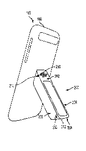
[0026] Referring now to Figure 3, a multi-orientation stand 200 is shown.
The multi-
orientation stand 200 includes a first or top region 202 and a second or
bottom region 204
oppositely disposed from the top region 202. The top region 202 and the bottom
region 204 are
joined by a first side region 206 and a second side region 208 integrally
formed with, and
extending between, the top region 202 and the bottom region 204. Each of the
top region 202, the
bottom region 204, the first side region 206 and the second side region 208
include an outer
surface, referred to herein as a first surface 210, a second surface 212, a
third surface 214 and a
fourth surface 216, respectively. Additionally, each of the top region 202,
the bottom region 204,
the first side region 206 and the second side region 208 include an inner
surface, referred to herein
as a fifth surface 218, a sixth surface 220, a seventh surface 222 and an
eighth surface 224,
respectively. In combination, the fifth surface 218, the sixth surface 220,
the seventh surface 222
and the eighth surface 224 define a cavity 230 therebetween that extends
through the multi-
orientation stand 200. Although the cavity 230 is described above and
illustrated as extending
through the multi-orientation stand 200, it is contemplated that the cavity
230 may simply be a
recess within the multi-orientation stand 200.
[0027] Any of the surfaces described above in conjunction with the multi-
orientation stand
200 may be disposed at numerous angles configured to provide a variety of
support orientations for
the portable electronic device 100, as will be described in detail below. It
is to be understood that
the surfaces, particularly the first surface 210 and the second surface 212
may be relatively flat or
may include varying degrees of curvature. As illustrated, and in an exemplary
embodiment, the
first surface 210 and the second surface 212 are relatively flat and formed at
an incline or angle
250 relative to a rear face 232 of the multi-orientation stand 200. For
example, the first surface
210 and the second surface of the top region 202 each angularly extend along a
planar path from
the rear face 232 of the multi-orientation stand 200 to a front face 234 of
the multi-orientation
stand 200. The precise angle of the first surface 210 may vary, but is
typically an acute angle and
is generally shown at an angle between 10 and 80 relative to the rear face
232, and in the
embodiment shown, generally about 45 . At least one, but typically a plurality
of charging features
240 are disposed proximate the first surface 210. Similar to the plurality of
electrical connectors
166 of the rear surface 160 of the portable electronic device 100, it is
contemplated that the
plurality of charging features 240 extend outwardly away from the first
surface 210 in the form of
protrusions or are integrated as recessed regions within the first surface
210. It is further
7
= CA 02826458 2013-09-09
contemplated that the plurality of charging features 240 comprise a
combination of protrusions and
recesses. Furthermore, the plurality of charging features 240 may be arranged
in numerous
alignments, such as the relatively linear alignment shown. However, it is to
be appreciated that the
plurality of charging features 240 may be aligned in a relatively angled
arrangement, a non-linear
arrangement and/or a clustered arrangement. The preceding list of arrangements
is merely
illustrative of exemplary embodiments and is not intended to be limiting of
the particular
arrangement of the plurality of charging features 240.
[0028] Irrespective of the precise configuration of the plurality of
charging features 240, a
corresponding relationship is established between the plurality of charging
features 240 and the
plurality of electrical connectors 166, such that engagement of the portable
electronic device 100
and the multi-orientation stand 200 is facilitated. For example, and as
illustrated, the plurality of
charging features 240 and the plurality of electrical connectors 166 may be
arranged in a relatively
linear alignment, such that engagement of the portable electronic device 100
and the multi-
orientation stand 200 provide a plurality of desirable orientations in which
the portable electronic
device 100 is situated in during engagement to the multi-orientation stand
200. To ensure proper
alignment and orientation between the portable electronic device 100 and the
multi-orientation
stand 200, at least a portion of the plurality of charging features 240 are
formed of a magnetic
material, as is the case with the plurality of electrical connectors 166, as
described in detail above.
[0029] Engagement between the multi-orientation stand 200 and the
portable electronic
device 100 is facilitated by a magnetic attraction of the plurality of
electrical connectors 166 and
the plurality of charging features 240. The magnetic material forming the
plurality of electrical
conncctors 166 and the plurality of charging features 240 facilitate an
electrical connection
between the multi-orientation stand 200 and the portable electronic device
100, while maintaining
a structural connection in the precise orientation that is desired by a user,
i.e., "portrait" or
"landscape," as described below. The strength of the magnetic attraction
depends on the particular
application of use, with factors such as the weight and geometry of the
portable electronic device
100 influencing the required magnetic attraction. Generally, the magnetic
attraction is greater than
the gravitational force of the portable electronic device at the center of
gravity of the portable
electronic device 100, thereby ensuring maintenance of the center of gravity
of the portable
electronic device 100 within a portable electronic device perimeter. Magnetic
attachment between
8
CA 02826458 2013-09-09
the portable electronic device 100 and the multi-orientation stand 200
facilitates a readily available
attachment and detachment capability that advantageously reduces cumbersome
procedures
associated with inserting components within mating receptacles. Such an
attachment provides
greater adaptability of the multi-orientation stand 200 to engage a wide
variety of portable
electronic devices.
[0030] Referring again to Figure 2, with continued reference to Figure 3,
the portable
electronic device 100 includes a portable electronic device width 260 and a
portable electronic
device height 262, with the outer surfaces of the portable electronic device
100 comprising a
portable electronic device perimeter (not labeled). Similarly, the multi-
orientation stand 200
includes a multi-orientation width 264 and a multi-orientation height 266. The
outer portions of
the first surface 210, the second surface 212, the third surface 214 and the
fourth surface 216 form
a multi-orientation stand perimeter. Each dimension associated with the
portable electronic device
100 noted above is greater than each dimension associated with the multi-
orientation stand 200.
Specifically, the portable electronic device width 260 is greater than the
multi-orientation stand
width 264, the portable electronic device height 262 is greater than the multi-
orientation stand
height 266, and the portable electronic device perimeter is greater than the
multi-orientation stand
perimeter. As will be appreciated in the description below, while the portable
electronic device
100 is supported by the multi-orientation stand 200, regardless of orientation
of the portable
electronic device 100, when viewed from the front by a user, no portion of the
multi-orientation
stand 200 is visible, as the outer-most portions of the multi-orientation
stand 200 extend only to
inwardly located regions of the portable electronic device perimeter. The
reduced dimensions of
the multi-orientation stand 200, relative to the portable electronic device
100, provide ease of
portability of the multi-orientation stand 200. The multi-orientation stand
200 may be transported
within small areas, such as clothing pockets of a user, for example, thereby
decreasing undesirable
aspects of traveling with charging devices.
[0031] Referring now to Figures 4 and 5, the multi-orientation stand 200
is illustrated in a
supporting relationship with the portable electronic device 100. In the
illustrated embodiment, the
bottom region 204 is shown in contact and resting upon a relatively planar or
horizontal surface,
however, it is to be appreciated that any region, including the top region
202, the first side region
206 or the second side region 208 may be in contact with the horizontal
surface. Also in the
9
CA 02826458 2013-09-09
illustrated embodiment, the first surface 210 of the top region 202 is engaged
and supports the
portable electronic device 100, and more specifically the rear surface 160 of
the portable electronic
device 100. It is to be appreciated that engagement between the portable
electronic device 100 and
the multi-orientation stand 200 may be facilitated by any of the other
surfaces of the multi-
orientation stand 200. As described above, the first surface 210 includes the
plurality of charging
features 240 for engaging the plurality of electrical connectors 166, however,
any of the other
surfaces of the multi-orientation stand 200 may include such charging
features.
[0032] Upon engagement, the multi-orientation stand 200 may provide
support to position
the portable electronic device 100 in a desirable orientation. However, an
exemplary embodiment
comprising the plurality of charging features 240 provides an electrical
connection between the
multi-orientation stand 200 and the portable electronic device 100. The
invention provides that the
multi-orientation stand 200 acts as an interchangeable element between the
charging source and the
portable electronic device 100. Therefore, the multi-orientation stand 200
provides structural
rigidity to the portable electronic device 100, while still facilitating a
charge. Such an electrical
connection is advantageous if the multi-orientation stand 200 is in operable
communication with a
power source or if a multi-orientation stand power storing component (not
illustrated) is disposed
in the multi-orientation stand 200. Either configuration provides routing of
power to the portable
electronic device 100, and more specifically to the power storing component
142 disposed therein.
It is to be appreciated that a direct physical connection between the
plurality of charging features
240 and the plurality of electrical connectors 166 may facilitate routing of
power from the multi-
orientation stand 200 to the portable electronic device 100. However, it is
contemplated that a
wireless connection, such as induction may adequately route power to the power
storing
component 142.
[0033] The multi-orientation stand 200 is configured to support the
portable electronic
device 100 in a plurality of orientations. A first orientation 300 is
illustrated and corresponds to a
relatively vertical orientation of the portable electronic device 100. The
relatively vertical
oricntation may be referred to as a "portrait" orientation. As shown and
discussed in detail above,
the First surface 210 engages the rear surface 160 of the portable electronic
device 100, while at
least a portion of the bottom region 204 rests upon a horizontal surface. To
provide a desired
orientation of the portable electronic device 100, the first surface 210 and
the bottom region 204,
CA 02826458 2013-09-09
specifically the second surface 212 of the bottom region 204, are formed as
inclined, relatively flat
surfaces. The angle of the first surface 210 and the second surface 212
determine the angular
orientation of the portable electronic device 100. This feature may take the
form of various other
embodiments by varying the angles to achieve a desired portrait orientation to
provide a desired
orientation.
[0034] Referring now to Figure 6, a second orientation 400 is illustrated
and corresponds
to a relatively horizontal orientation of the portable electronic device 100.
The relatively
horizontal orientation may be referred to as a "landscape" orientation. In the
illustrated
embodiment, the multi-orientation stand 200 is rotated 180 degrees and the
portable electronic
device 100 is rotated 90 degrees to transition the portable electronic device
100 from the first
orientation 300 to the second orientation 400. The angled surfaces 210, 212
allow the multi-
orientation stand 200 to maintain a reliable support of the portable
electronic device 100
sub,equent to such a transition to the second orientation 400 from the first
orientation 300.
[00:5] As can be appreciated, the described and illustrated embodiments
provide
num:-.=rous alternative orientations that may be achieved by manipulation of
the multi-orientation
stand 200 and the portable electronic device 100. Additionally, it is
contemplated that the
geometrv of the multi-orientation stand 200 may be modified to provide
alternative orientations. It
is to be understood that the multi-orientation stand 200 provides a plurality
of orientations in which
the portable electronic device 100 may be situated. The plurality of
orientations allow a user to
selectively determine a desirable orientation of the portable electronic
device 100, which typically
varies from use-to-use of the portable electronic device 100.
100' (1 Referring now to Figure 7, the multi-orientation stand 200
includes a power source
port 280. which is shown as a blind bore, configured to receive a wired power
source, such as a
powcr cord 282. In the illustrated embodiment, the power source port 280 is
disposed within the
top rc-!, i on 202, however it is to be appreciated that the power source port
280 may be disposed
within any one of the top region 202, the bottom region 204, the first side
region 206 or the second
side region 208. Alternatively, the power source port 280 may be disposed in
more than one of the
regions. which may accommodate more desirable access in particular
orientations. The power
soui¨e port 280 is situated proximate the cavity 230, such that a portion of
the power cord 282 rests
11
CA 02826458 2013-09-09
substantially within the cavity 230. Disposing the power cord 282 within the
cavity 230 and
extending the power cord 282 to an inner surface of the multi-orientation
stand 200 reduces the
disturbance to the desired orientation and support of the portable electronic
device 100 during a
wired connection between the power cord 282 and the multi-orientation stand
200. As explained
herein, the power source port 280 is a blind bore within one of the regions
202, 204, 206 and/or
208. and in the exemplary embodiment shown does not extend through the region,
forming an
intermediate element portion 281 between the bottom of the blind bore and the
plurality of
charging features 240 within the intermediate element portion 281. One or more
electrical
connections (not illustrated) extend from the power source port 280 to the
plurality of charging
features 240, thereby routing power to the externally exposed plurality of
charging features 240.
[0037] The preceding description describes in one embodiment a multi-
orientation stand
syst cm for a portable electronic device, the multi-orientation stand
including a portable electronic
devHe and a first surface disposed in contact with the portable electronic
device for supporting the
portable electronic device in a plurality of orientations. Also included is at
least one charging
feature disposed proximate the first surface for routing power to a power
storing component of the
port 1)1e electronic device upon contact between the first surface and the
portable electronic device.
Fur11-er included is a stand width less than a portable electronic device
width. Yet further included
is a cand height less than a portable electronic device height.
[007] The preceding description describes in another embodiment a multi-
orientation
stan,1 system for a portable electronic device including a first portion
having means for supporting
the rortable electronic device in a plurality of orientations. Also included
is a second portion,
whcHn at least a portion of the bottom portion is configured to rest on a
relatively horizontal
surf-ce. Further included is a means for routing power to a power storing
component of the
port '1)1e electronic device, the means for routing power disposed proximate
the means for
sup' )rting the portable electronic device in the plurality of orientations.
Yet further included is a
mep-s for magnetically aligning the multi-orientation stand and the portable
electronic device, the
means for magnetically aligning disposed proximate the means for supporting
the portable
elec.ionic device in the plurality of orientations.
12
CA 02826458 2013-09-09
100391 The preceding description describes in yet another embodiment a
multi-orientation
stan,1 system for a portable electronic device, the multi-orientation stand
including at least one
magnetic charging feature disposed proximate a first surface for routing power
to a power storing
component of the portable electronic device, the first surface supporting the
portable electronic
devi .e in a plurality of orientations. Also included is a stand perimeter
defined by the first surface,
a second surface oppositely disposed from the first surface, a third surface,
and a fourth surface
oppositely disposed from the third surface, wherein the stand perimeter
extends to inwardly located
regions relative to a portable electronic device perimeter during orientation
of the portable
electronic device in any of the plurality of orientations.
[00-111 While several embodiments have been provided in the present
disclosure, it should
be understood that the disclosed systems and methods may be embodied in many
other specific
forms without departing from the spirit or scope of the present disclosure.
The present examples
are 1 ) be considered as illustrative and not restrictive, and the intention
is not to be limited to the
deta' Is given herein. For example, the various elements or components may be
combined or
inte,rated in another system or certain features may be omitted, or not
implemented.
[0041] Also, techniques, systems, subsystems and methods described and
illustrated in the
various embodiments as discrete or separate may be combined or integrated with
other systems,
mo(1 Iles, techniques, or methods without departing from the scope of the
present disclosure. Other
items shown or discussed as coupled or directly coupled or communicating with
each other may be
indirectly coupled or communicating through some interface, device, or
intermediate component,
whe.11er electrically, mechanically, or otherwise. Other examples of changes,
substitutions, and
alter Itions are ascertainable by one skilled in the art and could be made
without departing from the
spirit and scope disclosed herein.
13