Note: Descriptions are shown in the official language in which they were submitted.
1
Crossbow with Step
BACKGROUND
This invention relates generally to crossbows, and more particularly to
prods and/or stock accessories.
Crossbows are generally known in the art. Crossbows typically include a
bow assembly portion mounted on a stock portion, which typically includes a
string
latch and trigger assembly for holding a drawn crossbow string and selectively
releasing
it.
Crossbows have employed foot stirrups disposed beyond the end of the
stock portion. Foot stirrups have been fixedly engaged to the bow assembly
portion or
stock portion. A user may place the foot stirrup on the ground and place their
foot in the
foot stirrup, thus holding the foot stirrup and forward end of the stock
portion in place.
The user can then apply a drawing force to the crossbow string, to draw the
string
toward the string latch assembly to cock the crossbow. The crossbow string is
held by
the sting latch in a drawn configuration.
Crossbows that employ foot stirrups tend to be larger (e.g., by weight, by
volume, overall length, etc.) and/or more cumbersome due to the protruding
foot
stirrups, which may be permanently engaged with the stock assembly. For
example, a
crossbow that includes a protruding foot stirrup may be more difficult to
store, transport,
and/or operate.
There remains a need for novel crossbow designs that provide benefits
over the prior art. For example, there remains a need for crossbows having a
shorter
length. Also, for example, there remains a need for crossbows that can be
drawn safely.
Without limiting the scope of the claimed subject matter a brief summary
of some of the claimed embodiments is set forth below. Additional details of
the
summarized embodiments and/or additional embodiments may be found in the
Detailed
Description below.
CA 2826709 2019-01-14
2
A brief abstract of the technical disclosure in the specification is
provided as well.
BRIEF SUMMARY
In one or more aspects of the present disclosure, a prod may include a
rail-engagement portion configured to engage a rail extending along a
longitudinal axis
extending proximally from the rail-engagement portion and a peripheral surface
comprising a foot-engagement region.
In one or more embodiments, a prod may further include a bow-
engagement portion configured to engage a bow or a bow limb. The bow-
engagement
portion may be configured to engage a bow or bow limb such that the bow or the
bow
limb extends laterally from the bow-engagement portion. The foot-engagement
region
may be disposed proximal of the bow-engagement portion. The bow-engagement
portion may be configured to engage a bow that extends laterally from the
prod.
In one or more embodiments, the foot-engagement region of a prod may
be an integral portion of the prod.
In one or more embodiments, the peripheral surface including the foot-
engagement region may face proximally.
In one or more embodiments, a foot-engagement region may include a
substantially planar foot-engagement region surface. In one or more
embodiments, the
foot-engagement region surface may define a foot-engagement region plane,
which may
be, for example, perpendicular to the longitudinal axis of the rail.
In one or more embodiments, a foot-engagement region may include a
non-skid foot-engagement region surface. For example, a foot-engagement region
may
include at least one foot-engagement protrusion and at least one recess. In
one or more
embodiments, the foot-engagement region may include a plurality of alternating
foot-
engagement protrusions and recesses.
In one or more embodiments, a foot-engagement region may include a
first foot-engagement region surface and a second foot-engagement region
surface.
Each foot-engagement region may define a foot-engagement region plane (e.g.,
the first
foot-engagement region surface may define a first foot-engagement region
plane, the
CA 2826709 2019-01-14
CA 02826709 2013-09-10
3
second foot-engagement region surface may define a second foot-engagement
region
plane, etc.). Two or more of the foot-engagement region planes may be
substantially
parallel or substantially coplanar.
In one or more embodiments, a first foot-engagement region surface may
be configured to be engaged by a first foot or first foot garment and the
second foot-
engagement region surface may be configured to be engaged by a second foot or
second
foot garment.
In one or more embodiments, a first foot-engagement region surface may
be disposed laterally from the rail-engagement portion. The second foot-
engagement
region surface may be disposed laterally from the rail-engagement portion of
the prod on
an opposing side of the rail-engagement portion from the first foot-engagement
region
surface. In one or more embodiments, at least one of the first and second foot-
engagement surfaces may be dimensioned to receive a foot or a foot garment
thereon.
In one or more aspects of the present disclosure, a crossbow may include
a stock assembly and a bow assembly that includes a prod. A stock assembly may
include a rail, a latch assembly, and a trigger assembly. In one or more
embodiments, a
rail may define a first longitudinal axis. In one or more embodiments, a latch
assembly
may be engaged with the rail and may be constructed and arranged to releasably
hold a
bow string in a cocked configuration. In one or more embodiments, a trigger
assembly
may be constructed and arranged to release a bow string from a latch assembly.
In a
crossbow of the present disclosure, a bow assembly may be operatively engaged
with
the stock assembly and may include a prod, a bow, and a crossbow string. A
prod may
include, for example, a first foot-engagement region and a second foot-
engagement
region, wherein both of the first and second foot-engagement regions extend in
a
common plane perpendicular to the longitudinal axis of the rail. In one or
more
embodiments, a bow may be operatively engaged with the prod and may include a
first
bow limb that has a first limb end and a second bow limb that has a second
limb end. In
one or more embodiments, a bow assembly may include a crossbow string
operatively
engaged with the first limb end and the second limb end.
In one or more embodiments a first foot-engagement region may be
integral with the prod. In one or more embodiments, a first foot-engagement
region may
be disposed between the bow and the bow string.
CA 02826709 2013-09-10
4
In one or more embodiments of the present disclosure, a crossbow does
not include a separate foot stirrup (e.g., a dedicated foot stirrup).
In one or more aspects of the present disclosure, a crossbow accessory
may include a rail-engagement portion configured to engage a rail extending
along a
longitudinal axis extending proximally from the rail-engagement portion and a
textured
peripheral surface including at least two foot-engagement regions, wherein the
at least
two foot-engagement regions are disposed on opposing sides of the rail-
engagement
portion.
These and other embodiments which characterize the invention are
pointed out with particularity in the claims annexed hereto and forming a part
hereof.
However, for a better understanding of the invention, its advantages and
objectives
obtained by its use, reference can be made to the drawings which form a
further part
hereof and the accompanying descriptive matter, in which there are illustrated
and
described various embodiments of the invention.
BRIEF DESCRIPTION OF THE DRAWINGS
A detailed description is hereafter described with specific reference being
made to the drawings.
Figure 1 is a top view of at least one embodiment of a crossbow
including a prod according to the present disclosure.
Figure 2 is a side view (e.g., left side view) of at least one embodiment of
a crossbow including a prod according to the present disclosure.
Figure 3 is a bottom view of at least one embodiment of a crossbow
including a prod according to the present disclosure, depicting two feet or
foot garments
engaging the prod.
Figure 4 is another side view (e.g., left side view) of at least one
embodiment of a crossbow including a prod according to the present disclosure,
depicting at least one foot engaging the prod.
Figure 5 is a left-bottom-rear perspective view of at least one
embodiment of a crossbow including a prod according to the present disclosure,
depicting two feet or foot garments engaging the prod.
CA 02826709 2013-09-10
Figure 6 is a left-bottom-front perspective view of at least one
embodiment of a crossbow including a prod according to the present disclosure,
depicting two feet or foot garments engaging the prod.
Figure 7 is view B-B of Figure 4, depicting a bottom view of at least one
5 .. embodiment of a crossbow including a prod of the present disclosure,
depicting two feet
or foot garments engaging the prod.
Figure 8 is a top view of a portion of at least one embodiment of a
crossbow including a prod according to the present disclosure.
Figure 9 is view C-C of Figure 8, a left-bottom-rear exploded view of at
least one embodiment of a prod according to the present disclosure, shown with
three
rail-engagement members (e.g., screws, bolts, etc.).
Figure 10 is a left-top-front perspective view of at least one embodiment
of a crossbow including a prod of the present disclosure, with arrows
highlighting a
foot-engagement portion of a prod and a cap, which may cover and/or protect
the
crossbow limb bolts and limb bolt washers when the crossbow is being cocked.
Figure 11 is a left-top-front perspective view of at least one embodiment
of a crossbow including a prod of the present disclosure, shown with detached
caps,
which may, when attached, cover and/or protect the crossbow limb bolts and
limb bolt
washers when the crossbow is being cocked.
Figure 11 a is an enlarged close-up left-top-front perspective view of a
portion of at least one embodiment of a crossbow including a prod of the
present
disclosure, shown with detached caps, which may, when attached, cover and/or
protect
the crossbow limb bolts and limb bolt washers when the crossbow is being
cocked.
Figure 12 is a left-top-rear perspective view of at least one embodiment
of a crossbow including a prod of the present disclosure, shown with detached
caps,
which may, when attached, cover and/or protect the crossbow limb bolts and
limb bolt
washers when the crossbow is being cocked.
Figure 12a is an enlarged close-up left-top-rear perspective view of a
portion of at least one embodiment of a crossbow including a prod of the
present
disclosure, shown with detached caps, which may, when attached, cover and/or
protect
the crossbow limb bolts and limb bolt washers when the crossbow is being
cocked.
Figure 13 shows a plan view of another embodiment of a crossbow.
CA 02826709 2013-09-10
6
DETAILED DESCRIPTION
While the subject matter of the present disclosure may be embodied in
many different forms, there are described in detail herein one or more
specific
embodiments. This description is an exemplification of the principles of the
present
disclosure and is not intended to limit the present disclosure to the
particular
embodiments illustrated.
For the purposes of this disclosure, like reference numerals in the figures
shall refer to like features unless otherwise indicated.
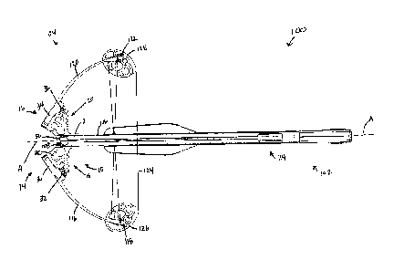
In one or more embodiments, with reference to Fig. 1, a crossbow 100 is
shown including a prod 10. In one or more embodiments, prod 10 may include a
rail-
engagement portion 12 configured to engage a rail 106 extending along a
longitudinal
axis A (e.g., a central longitudinal axis) extending proximally from the rail-
engagement
portion 12. Prod 10 may also include a peripheral surface including one or
more foot-
engagement regions 18, 20 (e.g., first foot-engagement region 18, second foot-
engagement region 20, etc.).
As shown in Figs. 1-8, prod 10 may include a bow-engagement portion,
which may be configured to engage a bow or a portion of a bow (e.g. limb). In
the
present disclosure, a prod may be configured with a recess or cavity in which
a portion
.. of a bow (e.g. limb) may be secured and through which a portion of a bow
may extend.
In one or more embodiments such as that shown in Figs. 1-8, prod 10 may
include a
plurality of bow-engagement portions 14, 16, each of which may engage a bow
limb
116, 120 (e.g., first bow limb 116, second bow limb 120, etc.). Bow-engagement
portions 14, 16 may be configured to engage a bow or bow limb such that the
bow or the
bow limb extends laterally from the bow-engagement portion. In some
embodiments,
the prod 10 may be engaged with (e.g., attached to) rail 106 by a rigid moment
connection. In some embodiments, the prod 10 may be engaged with (e.g.,
attached to)
a bow limb 116, 120 by a rigid moment connection.
In the present disclosure, it should be noted that a prod is not necessarily
required to transfer moment forces between multiple limbs. For example, if a
continuous limb is used, which spans continuously from one side of the bow to
the other
7
(e.g. from axle-to-axle), a structural member that attaches to the continuous
limb does
not need to transfer moment forces.
In the present disclosure, "front" refers to the end of a crossbow (or other
component) that faces a target of an arrow to be shot by the crossbow. For
example, in
some embodiments, the front of rail 106 abuts prod 10 at stop 50. In the
present
disclosure, "rear" refers to the direction opposite of "front." In the present
disclosure,
"proximal of' may be used interchangeably with "in front of' and "distal of'
may be
used interchangeably with "in the rear of." That is, it may also be said that
rail 106 is
distal of stop 50, whereas stop 50 is proximal of rail 106, which extends
between the
distal end 108 (Fig. 1) of rail 106 and the proximal end 110 (Fig. 2) of rail
106.
Further, "left" and "right" will refer to opposing "lateral" directions with
respect to rail
106 or prod 10 (or other component) which faces left or right from the
crossbow. For
example, the left side of rail 106 is shown in Fig. 2. For another example, in
Fig. 1, bow
limb 116 extends laterally from first bow limb engagement portion 14 of prod
10. In the
present disclosure, "top" refers to the direction that the portion of a
crossbow (or other
component) seen in Fig. 1 faces. "Bottom" refers to the direction opposite of
"top."
Herein, "vertical" refers to the up-down direction.
Generally, when a crossbow is drawn, a drawing force is applied to a
portion of the bowstring 124 in the rear direction toward a latch assembly
114. As the
bowstring 124 moves rearward, the limbs 116, 120 flex and store energy. The
bow
string 124 may be retained in a cocked position by the latch assembly 114
(Fig. 2). A
trigger assembly (e.g., including a trigger) 112 may selectively release the
string 124
from the latch assembly 114. which will allow the crossbow 100 to fire an
arrow or bolt
(not shown). In order to hold the crossbow in place while drawing, a
counterforce must
be applied in the forward direction to keep the rail 106 stationary.
Trigger assemblies are generally known in the art. For example,
Darlington (U.S. Pat. No. 5,884,614) and Simonds (U.S. Pat. No. 4,693,228)
each
disclose exemplary suitable trigger assemblies.
Figs. 3 and 4 show the positioning of a foot or foot garment 200, 202
disposed on a prod. For example, in Fig. 3, first foot or foot garment 200 is
depicted as
engaging foot-engagement region 18 of prod 10 and second foot or foot garment
202 is
CA 2826709 2019-01-14
CA 02826709 2013-09-10
8
depicted as engaging foot-engagement region 20. In this manner, a crossbow
hunter
may brace one or both feet against prod 10, as shown in Figs. 3-7 in order to
provide a
counterforce for drawing bow string 124 to be cocked.
It should be noted that, in some embodiments, foot-engagement region(s)
18, 20 may be disposed distal of the bow-engagement portion(s) 14, 16. That
is, a foot-
engagement region 18, 20 may be disposed between the bow-engagement portion(s)
14,
16 and the bowstring 124.
In the present disclosure, a bow-engagement portion 14, 16 may be
configured to engage a bow portion that extends laterally from the prod 10.
For
example, as shown in Figs. 1, 3, 6, and 8, each of bow-engagement portions 14,
16 is
configured to engage one or more of the components that comprise bow limbs
116, 120,
each of which extends laterally (e.g., in the left or right direction) from
the prod 10.
In the present disclosure, one or more foot-engagement region(s) 18, 20
may be an integral portion of the prod 10 assembly. That is, in some
embodiments, a
prod 10 is of a unitary construction that includes a foot-engagement portion,
a rail-
engagement portion, and a bow-engagement portion. A prod 10 of the present
disclosure may be constructed of any of a wide variety of materials that
provide the
requisite strength and durability in order to withstand the forces applied to
it (e.g., forces
imposed by a foot or foot garment, forces imposed by the rail or fasteners
engaging the
rail and prod, forces imposed by the bow or bow limbs in various
configurations
including at rest, cocking, drawn, and firing, etc.) when used, for example,
as a
component of a crossbow during an act of cocking the crossbow.
In the present disclosure, a foot-engagement region 18, 20 may include
any of, for example, a platform, a foot pad, a foot support, a foot rest, a
foot seat, a
pedal, and the like.
In one or more embodiments, a peripheral surface that includes one or
more foot-engagement regions 18, 20 faces distally. As shown in Figs. 3 and 5-
7, prod
10 includes a peripheral surface that faces distally and that includes one or
more foot-
engagement regions 18, 20. As shown in Fig. 9, first foot-engagement region
surfaces
64 face distally. In addition, second foot-engagement region surfaces 66 face
distally.
In one or more embodiments, a foot-engagement region 18, 20 may
comprise a substantially planar foot-engagement region surface. For example,
in Figs. 8
CA 02826709 2013-09-10
9
and 9, a first foot-engagement region 18 includes a substantially planar foot-
engagement
region surface 64, defining a foot-engagement region plane. In one or more
embodiments, a first foot-engagement portion 18 may include a plurality of
substantially
planar foot-engagement region surfaces 64, wherein the plurality of
substantially planar
foot-engagement region surfaces may or may not be coplanar. In Figs. 8 and 9,
the
various first foot-engagement portion surfaces 64 are coplanar.
In one or more embodiments, a foot-engagement region plane may be
perpendicular to the longitudinal axis of the rail 106 of the crossbow. For
example, in
Fig. 8, a foot-engagement region plane may be a plane defined by the first
foot-
engagement surfaces 64 and/or the second foot-engagement surfaces 66, which is
perpendicular to longitudinal axis A of rail 106. In some embodiments, a foot-
engagement region plane is orthogonal to the longitudinal axis A of the rail
106 of the
crossbow.
In one or more embodiments, a prod 10 may include a plurality of foot-
engagement region surfaces (e.g. 64) that are not coplanar (not shown) and/or
are not
perpendicular to the longitudinal axis A of the rail 106 (not shown).
The foot-engagement regions 18, 20 of the prods of the present
disclosure may include a first foot-engagement region surface and a second
foot-
engagement region surface. In one or more embodiments, a first foot-engagement
region surface may define a first foot-engagement region plane and a second
foot-
engagement region surface may define a second foot-engagement region plane,
wherein
the first and second foot-engagement region planes are substantially parallel.
In some
embodiments, the first and second foot-engagement region planes are disposed
at equal
but opposite angles to the longitudinal axis A of the rail 106. Alternatively,
in some
embodiments, the first and second foot-engagement region planes are not
substantially
parallel.
In some embodiments, the first and second foot-engagement region
planes may be substantially coplanar.
In the present disclosure, the first foot-engagement region surface may be
configured to be engaged by a first foot or first foot garment and the second
foot-
engagement region surface may be configured to be engaged by a second foot or
second
foot garment, as can be seen in Figs. 3-7.
CA 02826709 2013-09-10
As shown in Fig. 9, a first foot-engagement region surface 64 may be
disposed laterally from the rail-engagement portion 12. As can be seen in Fig.
9, a
second foot-engagement region surface 66 may be disposed laterally from the
rail-
engagement portion 12 on an opposing side of the rail-engagement portion from
the first
5 foot-engagement region surface 64. In some embodiments, the first foot-
engagement
region comprises a mirror image of the second foot-engagement region. In some
embodiments, surfaces 64 of the first foot-engagement region comprise mirror
images of
surfaces 64 of the second foot-engagement region, for example being
symmetrical
across a longitudinal axis of the prod 10.
10 In one or more embodiments of a prod 10 of the present disclosure,
at
least one of the first and second foot-engagement surfaces may be dimensioned
to
receive a foot or a foot garment thereon. For example, each foot-engagement
region
may have a lateral dimension of at least one half inch (e.g., at least 1 inch,
at least two
inches, at least three inches, at least 4 inches, at least 5 inches, at least
6 inches, etc.) In
one or more embodiments, the lateral dimension of each foot-engagement region
may be
less than half of the span of the undrawn bow string, wherein the span is the
distance
between contact points of the bowstring with the rotatable members (e.g. in a
compound
bow) or limbs (e.g in a non-compound bow). For example, the lateral dimension
of
each foot-engagement region can be less than 40% of the undrawn bowstring
length,
less than 30% of the undrawn bow string length, etc. Fig. 8 shows first bow
limb 116
having a first bow limb end 118. In Fig. 8, the lateral dimension of each foot-
engagement region is less than a distance between the first bow limb end 118
and the
rail 106.
A prod 10 of the present disclosure may include a foot-engagement
region that includes a non-skid foot-engagement region surface. For example, a
foot-
engagement region may include at least one foot-engagement protrusion and at
least one
recess. In one or more embodiments, the foot-engagement region may include a
plurality of protrusions separated by recesses. Fig. 8 shows prod 10 having a
foot-
engagement region 18, 20 having at least one (e.g., a plurality of) foot-
engagement
protrusion 62 and at least one (e.g., a plurality of) recess 64. In Fig. 8, a
plurality of
foot-engagement protrusions 62 alternate with recesses 60.
CA 02826709 2013-09-10
11
The alternating protrusion 62 and recess 60 structure can be oriented in
any suitable direction. For example, Figure 8 shows protrusions 62 and
recesses 60
alternating in a lateral direction. This orientation is best suited to prevent
a foot from
slipping in a lateral direction. In some embodiments, protrusions 62 and
recesses 60
alternate in a vertical direction (e.g. perpendicular to the orientation shown
in Figure 8.
In some embodiments, protrusions 62 and recesses 60 alternate in both lateral
and
vertical directions (e.g. forming a grid). Additionally, such a grid surface
can be made
with any suitable orientation, such as having recesses 60 oriented as various
angles to
those shown in Figure 8 (e.g. recesses 60 oriented 30 degrees, 45 degrees, 60
degrees,
etc.) In some embodiments, intersecting protrusions 62, or recesses 60, need
not be
oriented orthogonal to one another but can be oriented at various angles to
one another.
A foot-engagement region may, in one or more embodiments, include a
series of elongated foot-engagement protrusions (e.g., ridges, etc.)
alternating with a
series of recesses (e.g., grooves, etc.). Foot-engagement protrusions may take
a wide
variety of shapes (e.g., nodules, ridges, webs, lattices, etc.). Similarly,
recesses may
take a wide variety of shapes that complement the shape of the foot-engagement
protrusions. For example, in one or more embodiments in which the foot-
engagement
protrusions take the form of a web, a lattice, a honeycomb, or the like, the
foot-
engagement protrusions may be disposed individually between the webs,
lattices, and
honeycombs. In one or more embodiments in which the foot-engagement
protrusions
take the form of ridges, recesses alternating with the ridges may be elongated
(e.g.,
grooves) and disposed between the ridges. If the foot-engagement protrusions
are
nodules, the recesses may surround the nodules in the form of a web, lattice,
grid,
honeycomb, or the like.
Foot-engagement protrusions and recesses of the foot-engagement
regions may be configured to more securely engage a foot by, for example,
reducing the
likelihood of a foot slipping off of the foot-engagement region while cocking
the
crossbow. In one or more embodiments, the foot-engagement protrusions and
recesses
may correspond to the shape of the foot or foot garment of the crossbow user.
For
example, the foot-engagement regions may be constructed and shaped to
correspond to
the shape and/or topology of the sole of the crossbow user's foot or foot
garment. In
one or more embodiments, the foot-engagement protrusions and recesses in one
foot-
,
CA 02826709 2013-09-10
12
engagement region may be the same as or a mirror image of the foot-engagement
protrusions and recesses in a second foot-engagement region. In one or more
embodiments, it may be preferred that a foot-engagement region includes
parallel and
alternating ridges and grooves extending from the top of the foot-engagement
region to
the bottom of the foot-engagement region (e.g., perpendicular to the lateral
directions),
which may reduce slippage in the lateral directions. Alternating grooves and
foot-
engagement protrusions (e.g., ridges, etc.) may be oriented in any suitable
direction
(e.g., oriented any number of degrees from vertical).
In one or more embodiments, any of a wide variety of materials having
enhanced gripping characteristics may be disposed within one or more recesses
to
provide additional contact surfaces (e.g., foot-engagement region surfaces)
for reducing
slippage of an crossbow user's foot or foot garment during, for example, the
act of
cocking the crossbow. A material with enhanced gripping characteristics may
be, for
example, a polymeric material (e.g., rubber, etc.) that may resiliently
compress and
conform to a sole of a crossbow user's foot or foot garment and/or may have
surface
characteristics (e.g., tackiness, compliance, etc.) that provide improved grip
and/or
friction.
A foot-engagement region as described herein can be provided on any
suitable portion of a crossbow. Figure 13 shows an example of a crossbow 100
having a
continuous limb 145. The crossbow 100 comprises a foot-engagement region 18
supported by a limb 145. Desirably, the foot-engagement region 18 comprises a
planar
surface oriented orthogonal to the shooting axis. In some embodiments, the
foot-
engagement region 18 is integrally formed in the limb 145. In some
embodiments, the
foot-engagement region 18 comprises an accessory that is attached to the
crossbow. In
some embodiments, a first foot-engagement region 18 and a second foot-
engagement
region 20 are defined on opposite sides of the shooting axis. In some
embodiments, the
first foot-engagement region 18 and the second foot-engagement region 20 are
defined
on a continuous integral structure.
In some embodiments, a crossbow 100 comprises one or more foot
engagement regions located forward of a limb (e.g. 116, 120, 145).
In one or more aspects of the present disclosure, a crossbow may include
a stock assembly and a bow assembly operatively engaged with the stock
assembly.
13
With reference to Fig. 2, crossbow 100 includes a stock assembly 102 and a bow
assembly 104 operatively engaged with stock assembly 102.
As shown in Fig. 2, a stock assembly of the present disclosure may
include a rail 106 that defines a first longitudinal axis A (Fig. 1), a latch
assembly 114
engaged with rail 106 and constructed and arranged to relcasably hold bow
string 124 in
a cocked configuration. Stock assembly 102 may also include a trigger assembly
112
constructed and arranged to release (e.g., selectively release) the bow string
from the
latch assembly in order to shoot an arrow (not shown) from the crossbow
toward, for
example, a target.
In the present disclosure, any suitable stock assembly may employ,
without limitation, any of a wide variety of latch assemblies known to one of
skill in the
art and any of a wide variety of trigger assemblies known to one of skill in
the art.
Likewise, rail 106 may take a wide variety of shapes and designs known
to one of skill in the art. In one or more embodiments the proximal end of
rail 106 may
engage the rail-engagement portion 12 of prod 10. Thus, a proximal end 108 or
proximal portion of rail 106 may be constructed and arranged to have a shape
and size
that corresponds with a complementary shape and size of the rail-engagement
portion 12
of prod 10. In one or more embodiments, the bottom of a distal end 108 of rail
106 may
take a V-shaped configuration, which may be received by the top surface of a
rail-
engagement portion 12 of a prod 10, wherein the rail-engagement portion is a V-
shaped
rail-engagement portion 70 (Fig. 9). In one or more embodiments, one or more
prod-rail
fasteners 72 (e.g., bolts, screws, pins, etc.), as shown in Figs. 6 and 9, may
be used to
secure prod 10 to rail 106. Any appropriate prod-rail fastener in any suitable
quantity
may be chosen by one of skill in the art. The V-shaped engagement features
desirably
provide for a self-aligning interface between the connected portions. A self-
aligning
interface is further discussed in US Patent No. 9341430.
A crossbow of the present disclosure may include a bow assembly,
wherein the bow assembly includes a prod (as described herein) and a bow
operatively
engaged with the prod. For example, a prod may include a first foot-engagement
region
and a second foot-engagement region, wherein both of the first and second foot-
engagement regions extend in a common plane perpendicular to the longitudinal
axis of
the rail. For example, Fig. 8 depicts prod 10 with first and second foot-
engagement
CA 2826709 2019-01-14
14
regions 18, 20, wherein the first and second foot-engagement regions extend in
a
common plane perpendicular to the longitudinal axis A of rail 106.
With further reference to Fig. 8, crossbow 100 may include a bow
assembly 104 that includes a first bow limb 116 that has a first limb end 118
and a
second bow limb 120 that has a second limb end 122. Further, a bow assembly
104 may
include a bowstring 124 operatively engaged with the first limb end 118 and
the second
limb end 122. Herein, operative engagement of the bowstring 124 with first and
second
limb ends 118 and 122 may be dircct engagement (e.g., the bowstring tied to or
otherwise in direct contact with first and second limb ends 118, 122, etc.) or
by indirect
engagement, for example, via cams, pulleys, grooved washers, bolts, axles,
etc.
An exemplary dual cam compound crossbow is depicted in the figures.
For example, Fig. 8 shows first cam assembly 126 at first limb end 118 and
second cam
assembly 128 at second limb end 122. The bow assembly 104 may include any
suitable
bow arrangement, for example, including a recurve bow assembly, a compound bow
.. assembly, etc. A compound bow assembly may include any suitable type of
compound
bow arrangement, such as single cam, two-cam, 1.5/hybrid/CPS cam, etc. A
compound
bow assembly may further include a dual-synchronization arrangement, as
disclosed by
Darlington (U.S. Pat. No. 6,990,970), or a force vectoring anchor arrangement,
as
disclosed by McPherson (U.S. Pat. No. 8,020,544).
A crossbow of the present disclosure may include a prod having an
integral first foot-engagement region, wherein the first foot-engagement
region is
optionally disposed between the bow (e.g., bow limbs 116, 120) and the bow
string 124.
It may be noted that a prod of the present disclosure includes at least one
foot-engagement portion for applying a counterforce while cocking the
bowstring.
Because the sole purpose of a dedicated foot stirrup is for applying a
counterforce while
cocking the bowstring, a crossbow, including a prod of the present disclosure,
need not
include a foot stirrup. Herein, "stirrup" means a loop, ring, or other
construction that
surrounds (e.g., encircles, circumscribes, etc.) a foot or foot garment,
wherein the foot or
foot garment is disposed within the loop, ring, or other construction and
applies a force
CA 2826709 2019-01-14
CA 02826709 2013-09-10
against an inside surface of the loop, ring, or other construction. It may be
noted that a
stirrup includes an inner surface for engaging a foot or foot garment and does
not
include a peripheral surface (e.g., does not include a surface facing
outwardly from the
periphery of the stirrup, does not include an outer peripheral surface, etc.)
that further
5 includes a foot-engagement region. In one or more embodiments of the
present
disclosure, a crossbow might not include a dedicated foot stirrup. That is,
one or more
embodiments of a crossbow may include a prod that includes a foot-engagement
region
that does not surround (e.g., encircle around the bottom, sides, and top of) a
crossbow
user's foot or foot garment.
10 The crossbows and prods of the present disclosure may provide one
or
more advantages. Cocking a crossbow while having, for example, two feet engage
the
prod may provide a more stable and safe cocking action. The ability to engage
a prod
with two feet/legs may also allow for higher cocking forces, because two
feet/legs
provide counterforce for cocking, which may permit higher arrow velocities.
The two-
15 foot method also balances forces laterally.
In one or more embodiments in which the foot-engagement region is
disposed between the bow limbs and the bowstring, the crossbow may be
constructed
without a foot stirrup protruding from the front end of the crossbow, which
may reduce
the size (e.g., weight, volume, etc.) of the crossbow, which may permit easier
storage,
transport, and operation. A prod having a unitary construction that includes a
foot-
engagement region surface may provide one or more advantages, such as, ease of
construction, fewer parts, increased durability and lifespan of a prod, and/or
the ability
to withstand additional wear relative to constructions having an attached foot-
engagement region surface. Moreover, one or more advantages may be provided by
a
prod having foot-engagement protrusions and recesses that may be configured to
more
securely engage a foot by, for example, reducing the likelihood of a foot
slipping off of
the foot-engagement region while cocking the crossbow, resulting in a safer
crossbow.
In some embodiments, a foot engagement region as described herein is
provided on a crossbow accessory, and the accessory is attached to a suitable
portion of
the crossbow. In one or more aspects of the present disclosure, a crossbow
accessory
may include a rail-engagement portion configured to engage a rail extending
along a
longitudinal axis extending proximally from the rail-engagement portion; and a
textured
16
peripheral surface including at least two foot-engagement regions, wherein the
at least
two foot-engagement regions may be disposed on opposing sides of the rail-
engagement
portion. The present disclosure includes one or more embodiments in which a
step-
accessory may be provided as an after-market accessory to a crossbow, wherein
the step-
accessory may be installed on a crossbow rail via the rail-engagement portion
and may
provide a textured peripheral surface including at least two foot-engagement
regions. In
various embodiments as an accessory, the accessory may or may not engage a bow
assembly/portion of the crossbow (e.g., a bow, one or more bow limbs, etc.).
In one or more embodiments, a crossbow accessory may include a bow-
engagement portion configured to engage a bow (or one or more bow limbs) and
may
further include a textured peripheral surface including at least two foot-
engagement
regions. The at least two foot-engagement regions may be disposed on opposing
sides
of a rail of a crossbow. In various embodiments as an accessory, the accessory
may or
may not engage a rail, or another portion of a stock assembly.
In one or more embodiments of the present disclosure, a prod may be
configured to engage a vibration dampener, for example as described in US
Patent No.
6257220. For example, a prod 10 can comprise one or more apertures into which
a
vibration dampener (not shown) may be received and secured. Any of a wide
variety of
apertures and corresponding vibration dampeners may be known to one of skill
in the art
and may be suitable for use in one or more embodiments of the present
disclosure.
In one or more embodiments, the prod may be provided as an integral
portion of the rail (or stock assembly) and may include a bow-engagement
portion. In
one or more embodiments, the prod may be provided as an integral portion of
the bow
assembly (i.e., the prod forms a portion of the bow) and may include a rail-
engagement
portion.
In one or more embodiments, a prod of the present disclosure may be
configured with a limb nut aperture (e.g., a cylindrical aperture) into which
a limb nut
may be received, wherein the limb nut may have a cylindrical outer surface
having a
centrally located longitudinal axis. In one or more embodiments, the limb nut
may
include a limb bolt aperture, having a longitudinal axis, extending
therethrough that is
transverse to the cylinder's longitudinal axis. The limb bolt aperture of the
limb nut
may receive, for example, a threaded end of a limb bolt therein. The limb bolt
aperture
CA 2826709 2019-01-14
17
may be threaded and may engage the corresponding thread of a limb bolt. In one
or
more embodiments, the limb bolt may extend through the limb nut and be secured
on
the opposing side using, for example, a second nut or other fastening member.
Fig. 8
shows a prod 10 including a first limb nut aperture 26 and a second limb nut
aperture
28. Figs. 7, 11, 11 a, 12, and 12a depict a crossbow 100 that includes a prod
10
according to the present disclosure, wherein prod 10 includes first and second
limb nut
apertures 26, 28 having disposed therein first and second limb nuts 42 and 44
engaging
first and second limb bolts 38, 40.
In one or more embodiments, one or both of the first and second bow-
engagement portions may include a bow limb cup secured by a limb bolt. In some
embodiments, a bow limb cup is configured to pivot on portion of a prod. For
example,
Fig. 8 depicts a prod 10 including a first bow-engagement portion 14 that
includes a first
bow limb cup 30 mounted to prod 10 and arranged to pivot on a protrusion 32.
Fig. ha
shows a first limb bolt 38 that may extend through the first bow limb cup 30,
a portion
of the prod 10 and be secured to the first limb nut 42 (not shown). Fig. 8
also depicts a
second bow-engagement portion 16 that includes a second bow limb cup 34,
secured to
prod 10 and pivotable on protrusion 36. Fig. ha shows a second limb bolt 40
that may
extend through the second bow limb cup 34, a portion of the prod 10, and
engage the
second limb nut 44. In some embodiments, adjustment of a limb bolt 40 with
respect to
its associated limb nut 44 causes a pivoting of the limb cup 34 with respect
to the prod
10. The pivoting in turn results in more, or less, flex in the limbs (e.g.
120), which can
change the draw weight of the bow.
In some embodiments, limbs 116, 120 are receivable in a limb cup 30, 34
without removing the limb cup 30, 34 from the prod 10. For example, a suitable
limb
cup and limb arrangement is taught in US Patent No. 8453635.
Also shown in Figs. 11, ha, 12, and 12a are first and second cover caps
46, 48, each of which may be secured over first and second limb bolts 38, 40.
In the
present disclosure, one or more cover caps 46, 48 may be used to cover and
protect one
or more limb bolts, one or more bow limbs, and/or one or more bow limb cups
during
the act of cocking the crossbow. With reference to Fig. 5, a crossbow user may
cock the
crossbow by orienting the crossbow such that the front end of the crossbow
rests against
the ground or floor. A crossbow user may place one or more feet or foot
garments
CA 2826709 2019-01-14
18
against the foot-engagement surfaces of the prod to keep the front of the
crossbow
stationary on the ground or floor while the crossbow user pulls the bow string
toward
the latch assembly. Depending on the configuration of the bow assembly, it may
be that
one or more limb bolts, bow limbs, and/or bow limb cups may contact the ground
during such a cocking procedure, which may cause structural and/or aesthetic
damage
thereto. Thus, one may employ one or more cover caps 46, 48 to cover and
protect the
limb bolts and which may be sized and configured to extend proximally such
that the
one or more cover caps 46, 48 would contact the ground or floor during the
cocking
procedure described above. The exterior surface of the one or more cover caps
46, 48
may be shaped and configured in order to further stabilize the crossbow
against the
ground or floor during the cocking procedure.
In some embodiments, the crossbow 100 is arranged such that the arrow
passes between a first bow limb 116 and a second bow limb 120. Desirably, the
limbs
116, 120 are spaced to allow an arrow to freely pass between the limbs 116,
120 without
contact. In some embodiments, the prod 10 includes an aperture (e.g., cavity,
recess,
etc.) for an arrow or bolt to pass through when the crossbow 100 is fired.
When the bow assembly 104 includes a continuous bow spanning
between first bow end 118 and second bow end 122, a moment transferring
connection
is not required between the prod 10 and bow, but may be used if desired. Thus,
in some
embodiments, a continuous bow may be attached to the crossbow 100 (e.g. to the
prod
10) via a single fastener (e.g., a bolt) or a plurality of fasteners.
In some embodiments, a continuous bow may be concave. In one or
more embodiments, a continuous bow may include both concave and convex
portions
and may include one or more inflection points.
In some embodiments, a crossbow comprises an anchor 88 (see e.g. Figs
11&12), which can be used with a cocking rope. In some embodiments, an anchor
88 is
located below the rail longitudinal axis A. In some embodiments, a crossbow
comprises
anchors as disclosed in US Patent No. 9423203.
An example of a crossbow having one or more limbs that span
.. continuously from axle-to-axle (or between bowstring ends) is disclosed in
US Patent
No. 9022013.
CA 2826709 2019-01-14
19
While reference has been made to various preferred embodiments of the
invention other variations, implementations, modifications, alterations and
embodiments
are comprehended by the broad scope of the appended claims. Some of these have
been
discussed in detail in this specification and others will be apparent to those
skilled in the
art. Those of ordinary skill in the art having access to the teachings herein
will
recognize these additional variations, implementations, modifications,
alterations and
embodiments, all of which are within the scope of the present invention, which
invention is limited only by the appended claims.
CA 2826709 2019-01-14