Note: Descriptions are shown in the official language in which they were submitted.
CA 02826715 2013-09-12
Ozone-Ultrasonic Treatment of Spent Caustic Wastewater
Technical Field
[0001] The present disclosure relates to wastewater treatment, and more
particularly to
treatment of spent caustic.
Background
[0002] Spent caustic is an aqueous waste stream in oil refineries and
petrochemical plants
when petroleum derived fluids are processed with aqueous sodium hydroxide. It
is formed out
of scrubbing processes where excess sulfur compounds are removed from refined
mid and final
products, creating a stream with very high amounts of hydrogen-sulfide,
organic disulfides,
phenolics, mercaptans, and other hydrocarbon compounds. In addition, high
residual sodium-
hydroxide makes pH range from 11-14. The spent caustic wastewater produced
from this
processing is typically dark brown in color, turbid, highly alkaline, contains
high levels of sulfides
and has a pungent odor characteristic of olefins and sulfides.
[0003] Although both oil refineries and petrochemical plants generate a
wastewater stream ,
that belongs to this category, the actual chemical composition of these
wastewater streams
varies significantly from one plant to another depending on site deployed
refining/purification
processes. For example, the oil refining spent caustic stream comes from
multiple sources, and
includes sulfidic, naphthenic, and cresylic spent caustic waters. Sulfidic
spent caustic is
generated by a scrubbing process of liquefied petroleum gas (LPG) and pentane
from catalytic
cracker (FCC), as well as continuous distillation unit (CDU). Naphthenic spent
caustic comes
from the Merox type treatment of kerosene. On the other hand, cresylic spent
caustic comes
from the Merox type treatment of visbreaker gasoline. Typical chemical
composition ranges
for these streams is shown in Table 1.
1
CA 02826715 2013-09-12
Table 1: Typical Spent Caustic Chemical Composition
Parameter [rig/L1 Sulfidic spent caustic Napthenic spent
Cresylic spent
caustic caustic
pH 11-13 11-14 ___ 11-14
COD 8,000-100,000 60,000-100,000 130,000-
220,000
TOC 500-50,000 10,000-30,000 25,000-60,000
Sulfides 2,000-50,000 <1 0-60,000
Sulfite ______________ 0.2-500 0.5-1 500-1,500
Mercaptans 0-30,000 <25 0-5,000
Thiosulfate 0-4,000 50-150 10,000-15,000
Phenols 0.3-30 2,000-10,000 15,000-20,000
[0004] The spent caustic is considered one of the most difficult streams to
handle by
wastewater treatment industry professionals. Typical conventional treatment
options range
from steam and/or air stripping, chemical oxidation to oxidation supported by
high pressure
and incineration. Disadvantages of using these techniques relate to high
capital deployment per
unit basis, high operating costs, incomplete treatment requiring additional
treatment steps and
associated safety concerns.
Summary
[0005] A process for treating spent caustic comprises steps of oxidation of
the spent caustic
while agitating the spent caustic using ultrasonic vibration, where sulfur-
based compounds are
converted into benign compounds (mostly sulfates), chemical
adjustment/treatment, where
wastewater pH is adjusted to meet downstream treatment and handling
requirements, and
additional treatment and/or polishing, where residual contaminants are removed
to meet
wastewater discharge criteria.
Brief Description of the Drawings
[0006] These and other features will become more apparent from the following
description in
which reference is made to the appended drawings wherein:
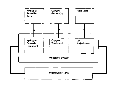
Figure 1 is an overview of an exemplary treatment process for treating spent
caustic;
Figure 2 is a system flow diagram for an exemplary treatment system for
treating spent caustic;
Figure 3 shows a US03 system on a base frame;
2
CA 02826715 2013-09-12
Figure 4 shows a side view of the U503 system of Figure 3;
Figures SA and 5B show, respectively, front and rear views of a U503 system
container; and
Figures 6 and 7 show an overview of the US03 system.
Detailed Description
[00071 As shown in Figure 1, in operation, wastewater is pumped from the
wastewater tank
through the process piping by a feed pump. The wastewater is filtered to
remove solids from it.
The filtered wastewater then passes through the treatment system and then
returns to the
holding tank. This is done continuously during the treatment process.
[0008] An exemplary system for treating spent caustic comprises a plurality of
modular
components that are designed to be transported to a client's facility,
assembled and operated
there temporarily to treat wastewater that has accumulated and is stored
there. Upon project
completion, the system is disassembled and removed. By treating the wastewater
at the site,
the risk of a potentially hazardous wastewater spill during highway transport
is obviated.
[0009] The exemplary system comprises at least one wastewater tank, a main
equipment
enclosure, a process feed pump, filter and heat exchanger module, at least one
hydrogen
peroxide tank, at least one acid tank, a gas catalyzer module, an oxygen gas
supply module and
a chiller, as well as suitable piping and hoses.
[0010] The wastewater tank contains the wastewater that is treated. In one
exemplary
embodiment, the volume of the wastewater tank is approximately 50,000 liters;
the
wastewater tank may be any suitable size. Carbon pillows are positioned to
obstruct openings
at the top of the tank and inhibit the emission of offensive odors.
[0011] The main equipment enclosure contains the equipment that chemically
treats the
wastewater, namely, hydrogen peroxide and acid pumps that inject these
chemicals into the
process stream, and ozone gas diffusers that introduce ozone gas into the
wastewater. It also
houses the ozone gas generator that feeds the diffusers, and its coolant pump.
[0012] Ultrasonic transducers that agitate the wastewater stream during
oxidation,
accelerating the chemical reactions, are plumbed downstream of each ozone
diffuser.
3
CA 02826715 2013-09-12
[0013] In a preferred embodiment, a 12-inch US03 system offered by Ultrasonic
Systems
GmbH, having an address at Gemeindewald 7a, 86672 Thierhaupten, Germany, is
used to
deliver ozone gas and provide ultrasonic agitation. The power connection is
128 amp Ceekon
400V, and the US03 system supports remote monitoring through a GSM or LAN
interface and
uses IPC control with WAGO SPS. Figures 3 to 7 show various aspects of the
US03 system.
[0014] The US03 for the treatment of a fluid contaminated with H2S is equipped
with an
additional outside pump/filter module and a plate heat exchanger downstream of
the
treatment cycle. The US03 unit itself is implemented in an insulated 40-foot
machine
container. The container also includes the main control center operating and
controlling the
unit. For security reasons the control center is separated from the actual
treatment area
through a wall including a gas-tight lockable door.
[0015] While filling the US03 a self cleaning filter system (downstream of the
pump) removes
larger impurities from the water. In order to make sure the unit is filled
completely, a level
sensor is placed at the end of the treatment system. Once the system is
completely filled, the
oxidation process is started by feeding ozone through the injection points at
the six included
OptimiXers, The six OptimiXer units are fed by three water/air cooled ozone
generators each
supporting 2 OptimXers. The desired amount of ozone gas is controlled and set
through mass
flow controllers (MFC). Each of the six OptimiXers has its own MFC. To protect
the MFCs
against a backflow of liquid, each OptimiXer injection nozzle is equipped with
a directly
actuated solenoid valve and a cone check valve.
[0016] In parallel to the ozone injection the ultrasound generators are
activated. The high
intensity ultrasound accelerates and improves the oxidation process.
[0017] In front of each OptimiXer a collector pipe removes residue ozone gas
to a catalyst unit
placed at the outside of the container. The catalyst unit consists of two
independent systems,
one for residual ozone and one for H2S gas. Therefore the residue gas streams
are guided out
of the US03 system and are converted into environmentally non-harmful
substances.
[0018] Four roller shutters alongside the complete container length (two on
each side) protect
the six ultrasound sections and The six OptimiXer gas injection points against
human contact.
4
CA 02826715 2013-09-12
The roller shutters can be opened electrically or, in case of a power failure,
manually, for
maintenance or repair work.
[0019] Before the treated liquid is discharged, it is led through a safety
plate heat exchanger.
The main function of this heat exchanger is an immediate cooling of the liquid
in the event of
an excessive heat dissipation of the ozonized H2S medium. In this case a 2/2-
way ball valve
automatically opens the cooling water connection to the plate heat exchanger
and the heat
dissipation is reduced to an acceptable level. In order to control the
temperature curve of the
H2S-liquid on a constant level, each ultrasound section is equipped with a
temperature sensor
PT100. By reducing the ozone amounts or ozone concentrations an uncontrolled
oxidation
process is avoided. The adjustment of the ozone amounts and ozone
concentrations is
preferably automatically controlled by a computer control unit.
[0020] After the plate heat exchanger the treated liquid can be discharged to
a storage tank,
placed on a lower level than the pump level, and can be circulated back into
the wastewater
tank until the desired result is achieved.
[0021] An on-board power supply (battery) enables the system to be drained,
purged and put
into stand-by mode in a controlled manner in the event of a power failure
(indicated by an
orange light on the container roof).
[0022] A 100mm floor pan is positioned below the OptimiXers and ultrasound
sections; in case
of leakage the liquid is collected in the floor pan and can be drained by a 3
inch floor
connection in the container bottom.
[0023] In other embodiments, other oxidation and ultrasonic agitation systems
other than a
MOS system may be used. A treatment system may other comprise a plurality of
individual
systems and components connected together, for example as a permanent on site
treatment
facility.
[0024] In a preferred embodiment, the treatment system's computer control and
electrical
distribution systems are located inside the equipment enclosure. The
electrical distribution
system provides electrical power and overcurrent protection for all of the
system's electrical
devices,
CA 02826715 2013-09-12
[0025) The control system continuously monitors data from the treatment
system's
temperature, pressure, level and flow sensors, chemical analyzers and inputs
from the user. It
controls flow of process fluids and progression of the treatment process. It
also enunciates
warnings to the user and shuts the system down if an unsafe condition exists.
[0026] Hydrogen sulfide and ozone gas detectors that are located in the main
equipment
enclosure are monitored by the control system. They enunciate an alarm and
shut down the
treatment system if hydrogen sulfide or ozone gas is detected outside of the
process piping in
excess of predetermined levels (i.e. leakage); in a preferred embodiment this
will occur if
hydrogen sulfide or ozone gas is detected outside of the process piping at
levels over 10 parts
per million (ppm) or 0.1 ppm, respectively. If leakage is detected the system
is stopped,
drained and purged immediately (indicated by a red signal light on the
container roof). In
addition, ventilators instantaneously start to remove the toxic gases and
ventilate all rooms
inside the container. The ventilated air is fed through carbon filters to
limit harmful gas escape
into The environment.
[0027] The process feed pump, filter and heat exchanger module contains the
pump that
circulates the wastewater through the treatment system, a filter that removes
suspended solids
from the wastewater, and a heat exchanger that removes the heat that is
generated from
chemical reactions in the treatment process, preferably maintaining a process
temperature
below 30 C.
[0028] The hydrogen peroxide tank contains an aqueous solution of hydrogen
peroxide, and
the add tank contains an acid solution. The particular acid that is utilized
varies, depending
upon availability and the chemical characteristics of the wastewater being
treated. In one
preferred embodiment, the volume of the hydrogen peroxide tank and the volume
of the acid
tank are each 1,000 liters.
[0029] In a preferred embodiment, the gas catalyzer module comprises two
catalyzers that
utilize oxygen gas and a granular catalyst to remove ozone and hydrogen
sulfide gases from the
process and convert them to benign gases before releasing them to the
atmosphere.
6.
CA 02826715 2013-09-12
[0030] The oxygen gas supply module comprises a machine that extracts oxygen
from the
surrounding atmosphere to supply the oxygen gas that feeds the ozone gas
generator and
cataiyzers.
[0031] A compression chiller rejects process-generated heat to the surrounding
atmosphere
and allows for the process to operate at temperatures lower than ambient. This
accelerates
the process and increases its efficiency.
[0032] Process piping and hoses convey the wastewater stream from the
wastewater tank,
through the treatment system and return it to the wastewater tank. All
materials that are in
contact with the wastewater are either stainless steel or non-metallic
materials that have been
designed to convey the corrosive chemicals present in the wastewater.
[0033] Figure 2 shows a detailed system flow diagram for an exemplary
treatment system for
treating spent caustic.
[0034] The treatment system has 3 specific operating functions. During each
function, the
wastewater is sampled and analyzed, at regular intervals, for total sulfide
content and pH. The
function that is utilized to treat the wastewater is dependent upon the
particular chemical
characteristics of the wastewater being treated.
[0035] The first function is a peroxone reaction which decreases the total
sulfides in the
wastewater by oxidizing them with a combination of hydrogen peroxide (H202),
ozone gas (03)
and ultrasonic agitation. This function is utilized where the wastewater has a
total sulfide
content of over 10,000 ppm.
(0036] Generally, the composition of a spent caustic stream is based on
sulfides, mercaptans,
thiosulfate, and phenols. The oxidation reactions of sulfide and other reduced
sulfur
compounds by ozone and hydrogen peroxide 03/H202 (peroxone) can be used for
industrial
wastewater treatment. The peroxone reaction can generate the formation of
hydroxyl radicals
(ON) during the reaction. The relative oxidation power of hydroxyl radical is
higher (2.05) than
ozone (1.52) and hydrogen peroxide (1.31) independently [1]. The addition of
H202 to %can
initiate the decomposition of 03, resulting in the formation of 'OH radicals:
7
CA 02826715 2013-09-12
203 + H202 42 'OH + 302
[0037] The formation of 'OH during the peroxone reaction is controlled by a
number of
variables, including PH, temperature, peroxide concentration, ozone
concentration and
reaction time,
[0038] The typical reactions occurring during the oxidation of a spent caustic
wastewater
stream include the following [2]:
+ 4H2024 SO; + 4H20 (sulfides to sulfates at alkaline pH)
2RSH + H2024 RSSR + 2H20 (thiols to disulfides at alkaline pH)
RSSR + 5 H202+ 20H-4 212503- + 6 H20 (disulfides to sulfonic acids at alkaline
pH)
[0039] Carrying the reaction to sulfonic acid and/or sulfates is generally
enough to control
odors and reduce the amount of sulfides to acceptable levels,
[0040] To start the peroxone reaction, a metered amount of hydrogen peroxide
is added to the
wastewater, which oxidizes the sulfide contaminants in it. The hydrogen
peroxide is added by a
variable speed pump. This allows the rate of hydrogen peroxide addition to be
adjusted. The
flow rate of ozone gas into the system is also adjustable. The rate of
hydrogen peroxide
addition and the concentration of hydrogen peroxide solution being added are
dependent upon
the particular chemical characteristics of the wastewater being treated.
[0041] The second function decreases the total sulfides in the wastewater to
acceptable levels
with a combination of ozone gas and ultrasonic agitation. This function is
utilized where the
wastewater has a total sulfide content of less than 10,000 ppm. The rate of
ozone gas addition
and the concentration of ozone gas being added are dependent upon the
particular chemical
characteristics of the wastewater being treated.
[0042] The third function is to lower the pH of the wastewater. This function
is only utilized
when the total sulfide content of the wastewater has been decreased to 10 ppm
or less. This pH
adjustment is done by adding a metered amount of acid to the wastewater to
lower its pH,
preferably to approximately 7. The acid is added by a variable speed pump.
This allows the rate
of acid addition to be adjusted, if needed. The concentration of acid and the
rate of addition of
8
CA 02826715 2013-09-12
the acid are dependent upon the particular chemical characteristics of the
wastewater being
treated.
[0043] A typical caustic neutralization reaction using hydrochloric acid is as
follows:
NaOH +1-1C1 -) NaC1+ H20
[0044] Because pH adjustment is only done when the wastewater no longer
contains high
levels of sulfides, the release of harmful gasses into the environment can be
effectively limited.
[0045] Typical sulfidic spent caustic chemical composition and treatment
results are given in
Table 2.
Table 2: Influent Sulfidic Spent Caustic Composition and Treatment results
Parameter [mg/Li Sulfidic Influent Sulfidic
Effluent before
additional
treatment/polishing
PH _________________________________ 12-12.7 82-9.0
COD 30,000-70,000 1,100-6,700
TOC 7,200-14,800 1,180-2,050
Sulfides 27,000-42,000 <1
Sulfite 30-74 <1
Mercaptans _________________________ 3,800-6,900 <10
Thiosulfate 420-710 <20
Phenols 0-12 <1
[0046] The present description is provided by way of example. It will be
apparent to persons
skilled in the art that a number of variations and modifications can be made
without departing
from the scope of the claims.
[0047] The following references were referred to in the above description:
[1] Munter, R., Advanced Oxidation Process ¨ Current Status and Prospects.
Proc.
Estonian Acad. Sci, Chem., 2001, 50, 2, 59-80.
[2] Solvay Interox, Pty. Ltd. Hydrogen Peroxide Controlling Reduced Sulfur
Compounds.
www.solvayinterox.com.au 2001, 1-9,
9