Note: Descriptions are shown in the official language in which they were submitted.
CA 02827345 2013-09-12
WO 2013/024403
PCT/1B2012/054043
1
A DUAL STEERABLE VEHICLE
Technical Field
The invention generally relates to the field of riding vehicles.
Background
Whether used for transportation or recreation, tricycles may be used for
riders of
different sizes and capabilities. Some tricycles are configured to be
propelled and steered
by the rider. In some instances, tricycles are configured to be pushed from
behind, by an
individual, such as an adult pushing a child. Typically, when the tricycle is
propelled by
the rider, the rider uses the pedals attached to the front wheel and steers
the tricycle using
a handle which is typically connected to the front wheel. Tricycles configured
to be
pushed from behind sometimes include a mechanical steering mechanism to permit
an
adult walking behind the tricycle to mechanically turn the front wheel.
Summary
An exemplary embodiment of the invention may include a tricycle operable
between a first mode of operation steerable by a tricycle rider, and a second
mode of
operation steerable by an individual pushing the tricycle. In both such first
and second
modes, the frame of the tricycle is configured to rotatably support the rear
wheels and
configured to support the head tube at a fixed, non-adjustable distance from
the rear
wheels. That is, the distance between the head tube and the rear wheels need
not
necessarily be changed even when the front wheel axis location is changed from
one
mode to another.
More specifically, a tricycle may include a fork having at least one blade
configured to support a front wheel in a manner permitting the front wheel to
rotate about
CA 02827345 2013-09-12
WO 2013/024403
PCT/1B2012/054043
2
a front wheel axis. A stem may be configured to rotatably extend from the head
tube and
a rider handle, may be configured to turn the fork about a stem axis
transverse to the front
wheel axis, the rider handle, in the first mode, being configured to be
rotationally coupled
with the stem in a manner permitting a tricycle rider to exert forces on the
rider handle
and thereby turn the fork, and the rider handle in the second mode, being
configured to be
rotationally uncoupled from the stem, preventing forces on the rider handle
from turning
the fork, wherein the stem extends from the fork at an angle chosen so that
when the stem
axis leads the front wheel axis the pedals do not necessarily interfere with
the rider's feet,
while turning, without a need to alter a distance between the seat and the
head tube, and
wherein, in the first mode, the stem extends from the fork at an angle chosen
so that when
the stem axis trails the front wheel axis the pedals are oriented for pedaling
by a rider
without a need to alter a distance between the seat and the head tube.
The handle, in the first mode, may be rotationally coupled with the stem in a
manner permitting a tricycle rider to exert forces on the handle and thereby
turn the fork.
In a second mode, the handle may be rotationally uncoupled from the stem,
preventing
forces on the handle from turning the fork.
The tricycle may include a pair of rear wheels, a front wheel having opposing
sides and a front wheel axis, and a pair of pedals, where each pedal may be
configured to
rotate the front wheel. The tricycle may include a seat as well.
The foregoing is a summary a few exemplary features of a few embodiments, and
is not intended to be restrictive of the invention as hereinafter described
and claimed.
Brief Description of the Drawings
In the drawings:
CA 02827345 2013-09-12
WO 2013/024403
PCT/1B2012/054043
3
- Fig. 1 is a side view of a tricycle, without parental handle, and which
may be used
in a first mode of operation, according to an embodiment of the invention.
- Fig. 2 is a side view of a tricycle, having a parental handle, which may
be used in
a second mode of operation, according to an embodiment of the invention.
- Figure 3 is front view of the tricycle of Fig. 2.
- Fig. 4a is a side view of a front wheel fork and stem assembly
consistent with an
embodiment of the invention.
- Figure 4b is a perspective view of the front wheel assembly of Fig. 4a
with mud
guard added.
- Figure 5a is a front view of a handle assembly consistent with an
embodiment of
the invention.
- Figure 5b is a cross-sectional front view of a coupling assembly
consistent with
an embodiment of the invention.
- Figure 5c is a perspective assembly view of a stem and coupling member
consistent with an embodiment of the invention.
- Fig 6 is a cross sectional side view of a coupling member consistent
with an
embodiment of the invention.
- Figure 7 is a cross-sectional side view of a coupling assembly
consistent with an
embodiment of the invention.
- Figure 8 is a cross-sectional side view of another coupling assembly
consistent
with an embodiment of the invention.
- Figure 9a is a cross-sectional side view of yet another coupling
assembly in an
uncoupled position, consistent with an embodiment of the invention.
- Figure 9b is a cross-sectional side view of the coupling assembly of
Fig. 9a in a
coupled position.
- Figure 10 is a perspective view of a holding mechanism, according to one
embodiment of the invention.
- Fig. 11 is a schematic diagram of a tricycle, having a swivel wheel,
according to
another embodiment of the invention.
- Fig. 12 is a partial assembly view of the tricycle of Fig. 11;
CA 02827345 2013-09-12
WO 2013/024403
PCT/1B2012/054043
4
- Fig. 13 is a schematic diagram of an enlarged front tube of the tricycle
of Fig. 11.
- Fig. 14 is a schematic diagram of the enlarged front tube of Fig. 13
with an
associated interconnecting base.
- Fig. 15 is an assembly view of the front wheel assembly of the tricycle
of Fig. 11.
- Fig. 16 is a further assembly view of the front wheel assembly of the
tricycle of
Fig. 11.
- Fig. 17 is an assembly view of the coupling part of Fig. 16.
- Fig. 18 partial cut-away view of the shaft and the coupling mechanism
according
to an embodiment of the invention.
- Fig. 19 is an enlarged partial cross-sectional view of the shaft and the
coupling
mechanism of Fig. 18.
- Fig. 20 is a perspective view of a tricycle in its second mode,
according to an
embodiment of the invention.
- Fig. 21 is a perspective view of a tricycle in its second mode,
according to an
embodiment of the invention.
- Fig. 22 is an enlarged partial cross-sectional view of a front end of
the tricycle in
its second mode, according to an embodiment of the invention.
- Fig. 23 is a perspective view of a suspension mechanism, according to an
embodiment of the invention.
- Fig. 24 is a side view of the suspension mechanism, according to an
embodiment
of the invention.
- Fig. 25 is a bottom view of a front wheel and its pedals, according to an
embodiment of the invention.
- Fig. 26 is a side view of inner parts of a suspension mechanism,
according to an
embodiment of the invention.
- Fig. 27 is a perspective view of a portion of a front wheel assembly,
according to
another embodiment of the invention.
- Fig. 28 is a perspective view of parts of a front wheel assembly,
according to an
embodiment of the invention.
CA 02827345 2013-09-12
WO 2013/024403
PCT/1B2012/054043
- Fig. 29
is another perspective view of parts of a front wheel assembly, according
to an embodiment of the invention.
- Fig. 30 is another perspective view of parts of the front wheel assembly,
according to an embodiment of the invention.
- Fig. 31 is a further perspective view of parts of the front wheel assembly,
according to an embodiment of the invention.
- Fig. 32 is yet another perspective view of parts the front wheel assembly,
according to an embodiment of the invention.
Detailed Description
The terms of "front", "rear", "down", "up", "bottom", "upper", "horizontal",
"vertical", "right", "left" or any reference to sides or directions are used
throughout the
description for the sake of brevity alone and are relative terms only and not
intended to
require a particular component orientation.
Embodiments of the invention may include a tricycle operable between a first
mode of operation steerable by a tricycle rider, and a second mode of
operation steerable
by an individual pushing the tricycle. A tricycle, as used herein, includes
any vehicle with
a wheel in the front and two wheels in the rear. Fig. 1, for example,
illustrates is a side
view of a tricycle, and which can be used in a first mode of operation where a
rider may
propel the tricycle using pedals 141 and 142 (see Fig. 3). A second mode of
operation
may be accomplished when an individual behind the tricycle, pushes the
tricycle using,
for example, parental handle 500, as illustrated in Fig. 2.
Embodiments of the invention may include a tricycle having a frame and a pair
of
rear wheels for rotatable connection to the frame. As illustrated in Fig. 1,
exemplary
tricycle 800 may include a main frame 700 including head tube 707. Two rear
wheels
400 (see Fig. 3) may be supported toward the rear of the main frame 700. The
main
frame 700 may be made of any material or have any structure, shape, or
configuration
CA 02827345 2013-09-12
WO 2013/024403
PCT/1B2012/054043
6
capable of supporting a tricycle rider. For example, main frame 700 may
include metal
tubing or any other rigid material, and may be configured to support a seat
600.
In one embodiment, the rear wheels 400 may be rotatably supported on a central
axle (the support shaft 702 of which is illustrated in Fig. 3) which may be
inserted into
the rear part of the main frame 700, effectively allowing the rear wheels 400
to rotate
frontwards or backwards. A seat 600 may be connected, by any known method, to
the
main frame 700. The seat may have any configuration capable of supporting a
rider. It
may include or omit a back rest, may be integrally formed or formed of
multiple
materials, and/or may be uncovered or covered in cloth, fabric, or other
material.
The main frame 700 may also have a number of connection options for seat 600,
effectively allowing the placing/adjustment of seat 600 at a number of
locations along the
main frame 700. In one embodiment, a basket 410 may be added and placed on the
rear
part of main frame 700 between the rear wheels 400.
Fig. 2 is similar to Fig. 1, adding a parental handle, which may be permanent,
semi-permanent (e.g., removable with tools), or designed to be removable at
will. The
term "parental handle" as used herein, includes any structure, regardless of
shape or
material that may be grasped by an individual behind a tricycle and used to
propel the
tricycle from behind. By way of example, parental handle 500 illustrated in
Fig. 2, may
be made of one or more metal pipes or from any other rigid material. In one
embodiment,
the parental handle 500 may be telescopically adjustable to accommodate the
height of
the individual pushing the tricycle 810. The adjustable height mechanism of
parental
handle 500 may belong to any of the known adjusting techniques such as by a
popup pin
held within the inner pipe of the handle and which pops out of one of the
holes of the
outer pipe, where the pin may be pushed from one hole and popped out of a
different
hole, for adjusting the height of the handle.
CA 02827345 2013-09-12
WO 2013/024403
PCT/1B2012/054043
7
Embodiments of the invention may also include a front wheel having opposing
sides and a front wheel axis. For example, and as illustrated in Fig. 3, front
wheel 100
includes first side 102 and opposing second side 104. The wheel 100, as
illustrated in
Fig. 4b, includes a central axis c at its midpoint 303, about which the wheel
100 is
rotatable.
Similarly, embodiments of the invention may include a pair of pedals, each
pedal
configured to rotate the front wheel. Numerous types of pedal may be employed
constant
with embodiments of the invention. Such pedals may include fixed pedals,
removable
pedals, foldable pedals, or pedals that flip up, retract, or have an otherwise
alterable
configuration. Thus, as used herein, the term pedal refers to any structure
that permits a
rider to propel a tricycle using foot power. An example of pedals, consistent
with
embodiments of the invention, include pedals 141 and 142 (see, e.g., Fig 3).
In addition, a
pedal may be configured to rotate the front wheel a portion of the time (e.g.,
during the
first mode when the rider propels the tricycle, and may be removable from,
disengagable
from, folded onto, or otherwise deactivatable during a second portion of the
time (e.g.,
during the second mode when a parent pushes the tricycle from behind).
Each of pedals 141 and 142 may be connected to the center of the front wheel
100, via pedal rod 140. The pedal rod may be continuous and connected to both
pedals,
or the pedal rod 140 may be configured of two independent sections, each
connected to a
separate one of the pedals 141 and 142. In a first mode of operation, the
propelling factor
of pedal rod 140 may be connected, by any mechanical interconnection means, to
a
rotating factor of the front wheel 100, thereby allowing rotation of the front
wheel 100
using pedal rod 140. By rotating the pedal rod 140, the front wheel 100 may be
rotated
about its center axis, i.e. about the middle part of pedal rod 140 which may
act as the
front wheel 100 axle. Alternatively, the front wheel may have a separate axle
to which
one or a pair of pedal rods connects.
CA 02827345 2013-09-12
WO 2013/024403
PCT/1B2012/054043
8
Pedal rod 140 may include three parts; a middle part located at a center of
the
wheel 100 and used, among others, as an axle of wheel 100, a left side for
connection to a
left pedal, and a right side for connection to a right pedal such as pedal
141.
Embodiments of the invention may include at least one blade configured to
support the front wheel in a manner permitting the front wheel to rotate about
the front
wheel axis. As used herein, the term "blade" includes any structure capable of
supporting
the front wheel in a rotatable manner. A wheel may be supported, for example,
on a
single blade or on a pair of blades. Fig. 4a illustrates an example of a blade
130 used to
rotatably support wheel 100. Fig. 3 illustrates wheel 100 supported by a pair
of blades
130 and 131. When a pair of blades are employed, they are typically
interconnected at
upper ends opposite points at which they interconnect to the wheel axis and
are
collectively referred to as a fork (although, as used herein, the term fork
may also include
structures that have just one blade.) Thus, in various figures, a fork is
generally
designated with the reference numeral 130. The fork may be formed of
individual blades
that curve toward each other, or, interconnecting structure may join two
individual fork
blades.
The middle part of pedal rod 140 may be pivotally held by the opposing distal
ends of fork blades 130 and 131 in a manner such that the front wheel is
capable of
rotating about its center axis. A mud guard 301 may be disposed near a top of
the fork
133, opposite distal ends supporting the wheel.
Embodiments of the invention may also include a stem configured to extend from
the head tube in a manner permitting the stem to rotate (i.e., rotatably
connectable to the
frame). A stem may be any structure connectable to the fork and that is
capable of
conveying a turning force to the fork and/or that supports the fork in a
rotatable manner.
For example, Fig. 4a illustrates stem 305 that extends from fork 133. Thus,
when either
the fork 133 or the stem 305 rotates, the other may rotate with it. The stem
may be
rotatably connected to the frame 700 via the frames head tube 707. The frame's
head tube
CA 02827345 2013-09-12
WO 2013/024403
PCT/1B2012/054043
9
707 may be a part of the frame 700, wielded to frame 700, or connected to
frame 700 by
any other means such as bonding, screws, threading, or any other mechanism
permitting
connection of a head tube to a frame.
In some exemplary embodiments, it may be beneficial to employ a stem geometry
that facilitates dual mode operation. For example, the maximum width of the
front wheel
(e.g., proximate the tread of the wheel) may be at least three times greater
than the
minimum diameter of the fork's stem. This configuration can lower turning
friction,
facilitating control from behind during the second mode of operation. In
another
embodiment, the stem may include a rod that has a minimum diameter that is at
least four
times smaller than an average width of the front wheel. The rod may have any
structure
that permits rotation, and may have a solid, hollow, or semi-solid. For
example, the rod
may be constructed of metal or other rigid material. The stem may be comprised
of
sections having varying diameters. In the above examples, a smallest or
"minimum"
diameter may be of particular interest, especially if that minimum diameter is
at a
rotational stem connection.
For example, when the front wheel maximum width is about 50 mm, the stem
may have a minimum diameter of between about 6mm and 12 mm, or less. When the
front wheel maximum width is 55 mm, for example, the stem may have a minimum
diameter of about 13mm and 18 mm, or less. All else being equal, a narrower
diameter
stem facilitates greater steering control when the tricycle is pushed from
behind. Thus,
consistent with embodiments of the invention, the stem diameter may be less
than one
quarter the maximum front wheel width. By way of additional examplesõ when the
front
wheel maximum width is in a range of 45 to 55 mm, the stem may have a minimum
diameter of 9 to 18 mm. For example, when the front wheel maximum width is in
a range
of 20 to 60 mm, the stem may have a minimum diameter of 4 to 15 mm.
CA 02827345 2013-09-12
WO 2013/024403
PCT/1B2012/054043
The stem's minimum diameter may be greater than one third the maximum width
of the front wheel, and the invention, in its broadest sense is not limited to
any particular
dimension.
Regardless of the dimensions of the stem, it may be held by a bearing which
may
reduce turning friction and facilitate the second mode operation and the first
mode of
operation as well.
As illustrated, for example in Fig. 4a, stem 305 may have a central axis a,
and
fork 133 may have a fork axis b and the stem 305 may be connected to the fork
133 in a
manner such that the central axes a and b form an obtuse angle x there
between. Angle x
may be, for example, equal to or less than about 179 degrees. In some
embodiments,
angle x may be between about 1700-1740. In another embodiment the angle x may
be
between about 16504790. In a further embodiment the angle x may be between
about
165 -173 . In yet another embodiment, the angle x may be between about 1700-
1750. As
the angle x approaches 180 , an ability to control steering from behind in the
second
mode of operation may be facilitated by a minimum stem diameter of three to
four times
smaller than the maximum width of the front wheel. Thus, when the angle x is
between
165 -179 , a stem with a minimum diameter of three to four times smaller than
a
maximum width of the front wheel may be desirable. For example, as illustrated
in Fig.
4b, width w of front wheel 100 may be at least three to four times greater
than the
diameter d of stem 305. For example, when the front wheel width w is in a
range of 25 to
51 mm, the stem may have a minimum diameter d of 6 to 12 mm. For example, when
the
front wheel width w is in a range of 45 to 55 mm, the stem may have a minimum
diameter d of 9 to 11 mm. For example, when the front wheel width w is in a
range of 20
to 60 mm, the stem may have a minimum diameter d of 4 to 15 mm. In one
embodiment
the average diameter of the stem is at least three times smaller than the
average width of
the front wheel. For example, when the front wheel average width w is in a
range of 45 to
55 mm, the stem may have an average diameter d of 9 to 11 mm. For example,
when the
average front wheel width w is in a range of 20 to 60 mm, the stem may have an
average
CA 02827345 2013-09-12
WO 2013/024403
PCT/1B2012/054043
11
diameter d of 4 to 15 mm. In one embodiment, the maximum width of the front
wheel
may be at least three times greater than the maximum diameter of the fork's
stem. For
example, when the front wheel maximum width is in a range of 45 to 55 mm, the
stem
may have a maximum diameter of 8 to 15 mm. For example, when the maximum front
wheel width w is in a range of 20 to 60 mm, the stem may have a maximum
diameter d of
4 to 15 mm.
In embodiments of the invention, the stem axis may extend in a direction
transverse to the front wheel axis. As illustrated in Fig. 4b, for example,
the central axis
a of stem 305 extends in a direction transverse to (i.e., extends in a
differing direction)
and is offset from rotational axis c of front wheel 100 by a distance y. In
one
embodiment, the minimal distance y may be no more than about 50mm. In another
embodiment, the offset distance y is in the range of between about 18mm and
25mm. In
yet another embodiment, offset distance y is in a range of about 15mm and
40mm. As the
offset distance decreases with all else equal, so to decreases an ability to
turn the tricycle
from behind using parental handle 500. Thus, in one embodiment, when the
offset
distance is between 15 mm and 22 mm, the angle x between the stem and the fork
is
between about 7 and 10 degrees, and the minimum diameter d of the stem 305 is
at least
three times less than the width w of the front wheel. This combination of
geometries is
exemplary of a configuration that may permit a parent to steer, in the second
mode, when
the stem axis a leads the wheel axis c, or may permit the tricycle rider to
steer, in the first
mode, when the wheel axis c leads the stem axis a, as will be discussed later
in greater
detail.
In one embodiment the fork axis a is designed to lead the front wheel axis c
in the
second mode of parental steering control. The leading stem axis in such
instances
positions the pedals further rearward than they would ordinarily be if the
stem axis a
trailed the wheel axis c, e.g. as in the first mode, potentially giving rise
to a concern that
the pedals may be too close to the rider for comfort. However, by employing a
minimal
angle x between the fork and the stem, peddles 141 and 142 may be maintained
at a
CA 02827345 2013-09-12
WO 2013/024403
PCT/1B2012/054043
12
sufficient and comfortable distance from the rider without necessarily having
to adjust the
rider's position rearward, such as might occur with an adjustable frame
(although
adjustable frames may be used together with all embodiments of the invention).
Thus,
the frame 700 may be configured to maintain a fixed, non-adjustable distance
between
the fork stem and the rear wheels. This can occur, for example by constructing
the frame
700 from a fixed length, non-adjustable piece of material. Alternatively, the
frame may
be constructed of multiple pieces in a manner that does not necessarily
require adjustment
of the frame length during use.
In one embodiment, the shortest distance between the front wheel center and
the
imaginary line of the stem axis is between lOmm-30mm. In another embodiment,
the
shortest distance between the front wheel center and the imaginary line of the
stem axis is
between 15mm-25mm. In yet another embodiment, the front wheel axis is designed
to
trail the stem axis in the second mode of operation. The figure though is non-
limiting and
alternatives may be employed, consistent with principles of the invention
described
herein.
In one embodiment the maximum width of the front wheel is at least three times
greater than the minimum diameter of the fork's stem.
Embodiments of the invention may further include a rider handle, configured to
turn the fork about a stem axis transverse to the front wheel axis. As used
herein, the term
"rider handle" is used broadly to refer to any structure, regardless of shape,
material, or
size, that can be grasped by a tricycle rider and used to turn the front
wheel. For example
the rider handle may be in the form of a handlebar, with a curved rod-like
shape, or a
straight rod-like shape. Alternatively, the rider handle may be in the form of
a steering
wheel or other closed or opened loop structure capable of manipulation by a
rider. The
rider handle may have a solid or open core. Like other parts of the tricycle,
the rider
handle may be made of any material or combination of materials.
CA 02827345 2013-09-12
WO 2013/024403
PCT/1B2012/054043
13
The rider handle may be configured to turn the fork via a mechanical
interconnection with, for example, either the fork or the stem. The mechanical
interconnection may be direct or may include intermediate parts through which
forces
may be transferred via the rider handle to the front wheel.
By way of example only, a rider handle may include handlebar assembly 200
illustrated in Figs. 1 and 2. As illustrated in greater detail in Fig. 5a,
rider handle
assembly 200 may include a handlebar 115, an arm 201, and a coupling mechanism
202.
The rider handle, in a first mode, may be configured to be rotationally
coupled
with the stem in a manner permitting a tricycle rider to exert forces on the
rider handle
and thereby turn the fork, and the rider handle in the second mode, may be
configured to
be rotationally uncoupled from the stem, preventing forces on the rider handle
from
turning the fork. Rotational coupling and decoupling of the rider handle from
the fork
may be accomplished in numerous mechanical ways, and the invention, in its
broadest
sense, is not limited to any particular mechanical interconnection. Rather,
any manner in
which the rider handle may be coupled and uncoupled to the fork is considered
to fall
within the scope and spirit of the invention. Moreover, the location of a
coupling
decoupling mechanism is not necessarily critical to embodiments of the
invention. It may
be located between a rider handle assembly and a stem, or it may be located
between a
stem and a fork.
Thus, by way of example only, the coupling mechanism 202 may, in a first mode,
permit mechanical interconnection between the rider handle and the fork such
that when
a tricycle rider applies a turning force to the rider handle, the turning
force is conveyed to
the front wheel via the fork. In a second mode, the coupling mechanism 202 may
decouple the rider handle from the fork in a manner permitting the rider
handle to turn
freely without conveying turning forces to the fork. This may be accomplished,
for
example, by permitting selective coupling and decoupling of the rider handle
from the
CA 02827345 2013-09-12
WO 2013/024403
PCT/1B2012/054043
14
stem. (e.g., selective coupling and decoupling of rider handle assembly 200
and stem
305).
Thus, the term "couple", "coupling", "coupling mechanism" and "rotational
engageable" are meant herein to include any mechanical engagement which
transfers the
rotation of one part to the other coupled part, by causing it to rotate
similarly.
When, in a first exemplary mode of operation the steering of tricycle 800 is
accomplished using rider handle assembly 200, i.e. the turning, e.g. left or
right, of rider
handle assembly 200 turns the fork 130 which turns the front wheel 100, the
rider may
assume control of steering while simultaneously propelling the tricycle 800
using the
pedals 141 and 142. If when the rider is in control in the first mode, a
person walking
behind the tricycle tries to push the tricycle from behind using parental
handle 500, the
rider may prevent the person walking behind from assuming control. Thus the
rider
handle may be mechanically disconnected from the stem. When this occurs, the
rider
handle may cease to function as a steering mechanism and may simply function
as
support that the rider may grasp for balance or in order to permit a child to
pretend to
steer. In this circumstance, the rider handle may lock in a stationary
position rotationally
disconnected from the fork and front wheel, or may rotate freely within a
range of motion
independent of the fork and the front wheel.
There are many differing ways in which a handle assembly may be rotatably
coupled and decoupled from a fork or fork stem. The examples provided in this
specification are not intended to limit the invention to any particular
example. Other
coupling and decoupling mechanisms may be used such as a detent, a pin, a
screw
connector, or any other connectors. One example, illustrated in Figure Sc
involves an
engageable and disengageable coupling. For example, a coupling member 204
associated
with the rider handle assembly 200 may include a surface that selectively
mates with an
extension of the stem. As illustrated in Fig. Sc, for example, a shaped end
308 of stem
305 is selectively mateable with a corresponding shaped slot 307 of coupling
member
CA 02827345 2014-04-08
- 15 -
204. When the shaped end 308 is seated in slot 307, force exerted on the rider
handle
assembly 200 is capable of turning the stem 305, and consequently fork 133 and
wheel
100. When the shaped end 308 is decoupled from slot 307 of coupling member
204, the
rider handle assembly 200 may be incapable of turning the wheel 100.
The stem's top end 308, in this example, has an almost rectangular shape,
although for most of its length the fork stem 305 is round. The opening 307,
depicted in
silhouette since the opening 307 is hidden from this view point, has a
corresponding
shape thereto. Hence, while being inserted into the opening, the fork stem 305
is affixed,
i.e. it cannot rotate, inside the second coupling member 204. In one
embodiment, the use
a symmetrical shape for the stem's top 308 allows the inserting of the fork
stem in two
ways, one way for allowing the front wheel axis to lead the stem axis in a
first mode of
operation, and another way for allowing the front wheel axis to trail the stem
axis in the
second mode of operation. Moreover, the almost rectangular shape is non-
limiting and
many other, non-round shapes can be used for the purpose of affixing the fork
stem 305
inside the second coupling member's opening 307.
As illustrated in Fig. 5b, a knob 810, or any other manually activatable
release
mechanism, which may be a part of the coupling mechanism 202, may be used for
coupling the handle arm 201 to the fork's stem 305. Specifically, and as
described later
in greater detail, when knob 810 is lifted, decoupling occurs, and when it is
moved
downward onto stem 305, coupling occurs. Thus, in a first mode, rider handle
assembly
200 is rotationally engageable with the fork's stem 305 in a manner permitting
a tricycle
rider to exert forces on the rider handle 200 and thereby turn the fork. On
the other hand,
the rider handle 200 in the second mode, may be rotationally disengageable
from the
fork's stem 305 for preventing forces on the handle from turning the fork.
Examples of
other structures that may be used to selectively couple a handle to a stem
include
protruding spring-biased pins that can be depressed to decouple and which can
snap back
into place to couple; or using the pin 309 without part 810 for coupling and
decoupling
the ride handle 200 to the stem 305, as described in relations to fig. 7.
CA 02827345 2013-09-12
WO 2013/024403
PCT/1B2012/054043
16
Figure 5b is a cross-sectional view of a part of the coupling mechanism 202,
according to one embodiment of the invention. The mechanism 202 allows
coupling of
the handle arm 201 and the fork stem 305. Three main members are depicted in
the
diagram: a first coupling member 203, a second coupling member 204 and a
grasping
member 810 (or a knob). The first coupling member 203 is statically coupled to
the
handle arm 201, thereinside. In the middle of the first coupling member 203
there is a
shaft through which the fork stem 305 can be inserted. The second coupling
member 204
is positioned inside the top end of the first coupling member 203, being
slideable up and
down. In the bottom of the second coupling member 204 there is an opening 307
into
which the top end 308 of the fork stem 305 may fit. When the second coupling
member
204 is in its upper position, it is disengaged from the fork stem 305. When
the second
coupling member 204 slides down, the fork stem 305 is inserted into the
opening 307,
and a coupling is achieved between the second coupling member 204 and the fork
stem
305, and hence also between the steering arm 201 and the fork stem 305. In
order to affix
the fork stem 305 inside the second coupling member's 204 opening, the fork
stem 305
has a non-round shape in its top end and the opening has a corresponding shape
thereto,
as illustrated in a non-limiting way. The grasping member 810 is, on one hand,
external
to the handle arm's tube 201 and on the other hand internal and connected to
the second
coupling member 204, by a connecting element 309 such as a pin, a screw, or
any other
element. Thus by sliding the grasping member 810 up and down, the second
coupling
member 204 also slides up and down as well. Moreover, the grasping member 810
as
depicted in the diagram provides the individual using it a better grip and
easier control on
the second coupling member's 204 position (whether up or down). However, in
other
embodiments the grasping member 810 is redundant or not required, and then,
the
connecting element 309 alone may be used as a third coupling member, as
described in
relations to fig. 7. The connecting element 309 has been depicted as a single
element,
such as pin etc. connecting both sides of the third coupling grasping member
810 via the
handle arm 201 and the second coupling member 204. This is not mandatory
though and
in other embodiments other solutions can be applied instead. For example, by
having a
CA 02827345 2013-09-12
WO 2013/024403
PCT/1B2012/054043
17
third coupling member composed of two parts (e.g., a "right part" and a "left
part"), a
short pin can be coupled to each part, while the short pin can penetrate the
steering arm
and form the connection with the second coupling member, whereas, in another
embodiment, the two parts may be connected by a spring. In one embodiment
second
coupling member 204 may be designed from two interconnecting parts each made
from a
different material.
In one embodiment, the coupling mechanism 202 may be in the front tube 707 of
the frame 700. In other embodiments, the coupling mechanism may appear on top
of the
front tube 707. In other embodiments, the coupling mechanism may appear below
the
front tube 707.
Figure 6 is a cross-sectional view of the handle arm 201 holding the first
coupling
member 203, according to one embodiment of the invention. As depicted in the
diagram,
the first coupling member 203 is held by grasping elements 610, such as snaps,
in the
handle arm's tube 201. In the presently illustrated example, there are two
snaps holding
the first coupling element, one of each side, yet this in non-limiting and any
other number
of snaps can be used, as long as the first coupling member is affixed within
the steering
arm's tube. The shaft 306 is the shaft in which the fork stem may slide in.
These figures
though are non-limiting, and other coupling mechanisms may be used and other
alternatives may exist.
Figure 7 is a cross-sectional side view of the second coupling member 204
inside
the first coupling member 203, according to one embodiment of the invention.
In the
handle arm's tube 201 there are grooves 713. Through these grooves a guiding
element
714, connected to the second coupling member 204, can slide up and down, thus
lifting
and lowering, respectively, the second coupling member 204. The second
coupling
member 204 should stay in a low, down position when coupled to the pivot, and
in an
upper, high position when disconnected therefrom, a locking mechanism is
described.
According to one embodiment, this locking mechanism comprises protrusions 716
in the
CA 02827345 2013-09-12
WO 2013/024403
PCT/1B2012/054043
18
groove 713. When the guiding element crosses a protrusion 716, it is locked
therebehind.
In order to allow crossing of the guiding element, the protrusion should be
made of a
flexible or resilient material. In addition, if the steering arm is made of a
non-flexible
material, it is possible to attach thereto another layer of a flexible
material, either from
the inside or from the outside, forming the protrusion in this flexible layer.
In the present
embodiment, the first coupling member 203, which is attached to the handle
tube 201
from the inside, can form this layer. Hence, as illustrated in the diagram,
grooves are seen
also in the first coupling member 203, wherein the protrusions 716 are
implemented
therein. This is non-limiting though and instead of using the first coupling
member as the
flexible layer, other solutions may be provided as a dedicated piece of
flexible material
which is attached to the handle arm's tube instead. Yet other embodiments may
use other
solutions, alternative to the protrusions, such as using a screw as the
guiding element,
screwing it in the position where it needs to be locked.
In those cases when the coupling mechanism includes a knob, such as element
810, as described with reference to figure 5b, the guiding element may form
also the
connecting element 309. Alternatively, there may exist a connecting element
309, which
is additional to the guiding element. In one embodiment the guiding member
alone may
be the knob used for coupling and/or decoupling.
Figure 8 illustrates the knob 810, according to one embodiment of the
invention.
As was noted above, in one embodiment, the connecting element 309 is able to
slide up
and down in the groove.
Figure 9a is a cross-sectional side view of the coupling mechanism in the
uncoupled position. It can be seen, from looking at figure 9a that the top end
of the fork
stem 305 is free, that is, it is not inserted into the opening 307 of the
second coupling
member 204. Figure 9b is a cross-sectional side view of the coupling mechanism
in the
coupled position. In figure 9b, illustrating the coupled position, the top end
of the pivot is
inserted into the opening 307. In each one of the positions described with
reference to
CA 02827345 2013-09-12
WO 2013/024403
PCT/1B2012/054043
19
figures 9a and 9b, the fork stem 305 is rotatably held in the first coupling
member 203. In
order to keep the fork stem 305 held in the first coupling member 203, the
fork stem 305
has an indentation 910. The indentation may include, for example, a groove
that fully or
partially circumscribes the stem 305, or it may include a confined recess in
the stem 305.
A locking member 911 having a spring 912, clenching the pivot's indentation,
may
prevent it from sliding out and releasing therefrom. Therefore, the locking
member 911
may prevent the fork stem 305 from releasing from the coupling mechanism.
Figure 10 is a perspective view of the holding mechanism for engaging the fork
stem 305, according to one embodiment of the invention. The locking member
911, in
this case, has an oval opening 1010 through which the head of fork stem 305
can pass,
and one or more springs 912. The locking member 911 has a first side 1011 and
a second
side 1012. It is noted though that the locking member is not necessarily
rectangular and it
may not have definable sides. However, in order to explain the affixing
mechanism, the
embodiment illustrated is nearly rectangular in shape. When inserted into the
handle tube,
or into the first coupling member, the spring/springs 912 push the locking
member 911
towards its 1011 side, against the tube's wall. Upon inserting the fork stem
305 (see Fig.
9a), into the shaft 306 (see Fig. 6) of the first coupling member, the fork
stem 305 reaches
the locking member 911. Then, the top of the stem's end pushes the locking
mechanism
911 towards its 1012 side. When the stem's indentation reaches the locking
mechanism
911, the spring/springs 912 are slightly released and push the mechanism into
the
indentation, thus affixing the fork stem 305 in correspondence to the locking
mechanism
911 and hence also in correspondence with the first coupling member. The
mechanism
illustrated in figure 10 is non-limiting and many other one-time locking
mechanisms
known per se may be used alternatively, as applicable.
Embodiments of the invention may also include one or more rotation
restrictors.
These rotation restrictors may restrict the front wheel to a certain angle.
For example, in
the first mode, where the front wheel axis may lead the fork axis, the front
wheel may be
restricted to an angle D (See Fig. 21) of between 70 -100 in order to prevent
the front
CA 02827345 2013-09-12
WO 2013/024403
PCT/1B2012/054043
wheel, or the rider handle, from hurting the rider while riding. In another
embodiment,
the front wheel may be restricted to an angle of between 500-1500. In another
example, in
the second mode, where the front wheel axis may trail the fork axis, the front
wheel may
be restricted to an angle of between 700-1000 in order to prevent the front
wheel from
turning to a position where the front wheel axis leads the fork axis during
travel. In
another embodiment the front wheel may be restricted to an angle of between
500-1790
.
As used herein, "a rotation restrictor for preventing" includes any structure
capable of
restricting the rotational movement of the front wheel, regardless of whether
the restrictor
completely prevents rotation past a certain point, or whether the restrictor
only prevents
rotation past a certain point when forces exerted are below a threshold (e.g.,
the restrictor
may exert a bias force that may be overcome by an opposing force greater than
the bias
force.) In either instance, rotation restrictors consistent with embodiments
of the
invention may be used to maintain the front wheel in a certain temporal
orientation
whether the front wheel axis leads the fork axis or whether the front wheel
axis trails the
fork axis.
In one embodiment the rider handle angle is restricted due to safety
considerations, protecting the body of the rider from being hit by the rider
handle. In one
embodiment the turning angle of the rider handle may be between 800 and 100 .
In one
embodiment the turning angle of the rider handle may be around 90 . In one
embodiment
the turning angle of the rider handle may be between 20 and 170 .
With such configurations, in some embodiments, the front wheel of a tricycle
may
be maintained in one of two positions, according to first and second modes of
operation.
In a first mode of operation, the wheel axis may lead the stem axis and in a
second mode
of operation, the front wheel may be rotated backwards and maintained in a
position
where the stem axis leads the front wheel axis. Thus, in some embodiments, all
a parent
need do to take over steering control is to disengage the rider handle from
the front wheel
and turn the front wheel backwards. In one embodiment the rotating factor of
the pedal
rod may be disengaged from the rotating factor of the front wheel. In another
CA 02827345 2013-09-12
WO 2013/024403
PCT/1B2012/054043
21
embodiment the pedals may be folded as well. Similarly, if a parent is pushing
the
tricycle, and desires to turn steering control over to the rider, all the
parent need to do, in
this embodiment, is to turn the front wheel to the front and couple the rider
handle to the
front wheel. In one embodiment the rotating factor of the pedal rod may be
engaged to
the rotating factor of the front wheel. In another embodiment the pedals may
be unfolded
as well.
Depending on the embodiment, the tricycle may provide an option of changing
pedal position between modes of operation. In one embodiment a footrest 300
(see fig. 2)
may be connected to the main frame 700 for allowing the rider to rest his feet
on the
footrest 300 while the tricycle 810 is being pushed from behind. In one
embodiment the
footrest 300 is foldable, and it may be folded backwards under the chair 600
or it may be
folded in any other way. In one embodiment the pedal rod 140 propelling factor
may be
disengaged from the rotating factor of the wheel 102, effectively allowing the
pedals to
stay static while the tricycle 810 is being pushed. The method for engaging
and
disengaging the pedal rod propelling factor and the rotating factor of the
wheel is known
in the art. In the second mode of operation the rider handle 200 may be
uncoupled from
the fork 130, effectively allowing an individual to push the tricycle 810 from
behind and
steer it using the parental handle 500 while the rider sits on the chair 600,
rests his feet on
the foot rest 300 and rests his hands on the rider handle 200. Meaning that in
this second
mode of operation, the steering of the tricycle 810 does not have to interfere
with the
rider's hands holding the rider handle 200. Nevertheless, the tricycle 810 may
be changed
to the first mode of operation by coupling the fork 130 with the rider handle
200,
optionally detaching the parental handle 500, optionally folding the footrest
300, and
optionally reengaging the pedal rod 140 to the front wheel 102. Thus in the
first mode of
operation the rider can propel the tricycle 810 by himself using the pedal rod
140 and
steer the tricycle 810 by himself using rider handle 200.
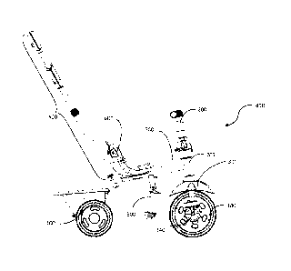
Fig. 11 is a perspective view of a tricycle, having a swivel wheel, according
to
another embodiment of the invention. The tricycle may include a frame a105, a
steering
CA 02827345 2013-09-12
WO 2013/024403
PCT/1B2012/054043
22
assembly a107, a front tube a106, which may be attached to the frame a105, and
which
pivotally holds the rider handle's al15 arm, a supporting structure a207, and
a pressure
transferring element a208 which is shown in its forward placement. The wheel
assembly
a108 includes a front wheel a102, a mud-shield a301, a pedal al16 and shock
suspension
al17, where, in the first mode of operation, the front wheel a102 may be
steered by the
steering assembly a107. In one embodiment, the supporting structure a207 and
the mud-
shield a301 may be made from one piece, however alternatives may exist, for
example,
the supporting structure a207 may be joined or disjoined from the mud-shield
a301, using
snap-ins, screws, or any other adjoining techniques. Two rear wheels such as
rear wheel
a104 may be located respectively at the two sides of the back of the frame
a105 and
rotatably held by the back of the frame a105. The frame a105 and the steering
assembly
a107, the wheel assembly a108 and the two rear wheels, may constitute the body
of the
tricycle vehicle, according to an embodiment. The tricycle vehicle may also
include one
or more of the following: a seat al10 which may be assembled and disassembled,
a
foldable leg support mechanism al 19, a handle a112 which enables an external
control of
the tricycle vehicle, and a basket a702. Furthermore, the tricycle may also
include an
enclosure a1201 attached to the front tube a106 for protecting the steering
assembly a107,
and for other purposes as well.
Fig. 12 is a partial assembly view of the tricycle of Fig. 11, having a swivel
wheel, where the enclosure a1201, is omitted. The rider handle al15 may
include a rail
a1151 and a vertical bar a1152, which extends from the center of the rail
a1151
downwards. A hole al153 may be configured on the vertical bar al152, and on
the lower
end of the vertical bar al152 a notch al154 may be configured. Inside the
bottom of the
front tube a106 may be configured a rotation restricting mechanism a712. The
tricycle
vehicle may include a mechanism a202, for coupling and decoupling the handle
bar al15
and the wheel assembly a108. In an embodiment, a turning sign a3011 may be
located on
the mud-shield a301 for indicating the front wheel's assembly a108 direction.
The
direction of the front wheel's assembly a108 may be changed by pressing the
pressure
transferring element a208 and switching the front wheel's direction.
CA 02827345 2013-09-12
WO 2013/024403
PCT/1B2012/054043
23
Fig. 13 is an enlarged perspective view of an assembly offront tube a106,
according to an embodiment of the invention. On the top end of the front tube
a106 two
notches a1061 may be located which are corresponding to the two notches a1062
(one
notch a1062 is hidden) on the lower end of the front tube a106. On the lower
part of the
front tube a106 two opening a1063 (one of the openings is hidden from view)
may be
located, on the upper part of the front tube a106 two openings a1064 may be
located as
well, where the four opening a1063 and a1064 may be separately located on the
position
of 1/4 of a circle from the two notches a1061, and a1062 respectively. The
notches a1061
and the opening a1064 may be configured for assisting in the assembly of the
enclosure
a1201. The notches a1062 and the opening a1063 may be configured for assisting
in the
assembly of the rotation restricting mechanism a712. The rotation restricting
mechanism
a712 may comprise the base a7121 and a shaft a7122 which extends upwards from
the
base a7121, on the upper part of the shaft a7122 two snaps a7123 may be
configured, and
on the lower part of the base two protrusions a7124 (one protrusion may be
hidden) may
be configured. While the shaft a7122 may be inserted into the front tube a106,
the snaps
a7123 correspond to the opening a1063 and locking therein, the protrusion
a7124 may
slide into the notches a1062 which have a corresponding shape thereto.
Fig. 14 is another enlarged perspective view front tube a106 and its
interconnecting base a7121, according to an embodiment of the invention. The
base
a7121 and the shaft a7122 are round shaped, and both are hollow in the middle
the base
having a hole a7125. On bottom of the base a7121 facing down are configured
two non-
continuing grooves, or recessed members, a7126 and a7127, where each has the
form of
an arch having two ends, substantially in the perimeter of the front tube
a106. The two
grooves (recessed members) a7126 and a7127 may be allocated on opposing sides
from
each other. In one embodiment, the grooves a7126 and a7127 may be formed
together
with the base a7121. Alternatives may be used as well, for example, the base
a7121 may
be composed from two pieces, and each groove may be configured on one of the
parts of
the base.
CA 02827345 2013-09-12
WO 2013/024403
PCT/1B2012/054043
24
Fig. 15 is a perspective assembly view of a front wheel assembly, according to
an
embodiment of the invention. The wheel assembly a108 may include a fork a304
which
may be affixed to two ends of the axle of the front wheel, and a stem a305
attached to the
top of the fork a304. The fork a304 may have a hole a3041 for assisting the
placement of
mudguard a301. On the top end of the stem a305 an indentation a3052 may be
located.
The part a202 may be formed of two parts a203 and a204, where the part a202
may be
connected to the stem a305. The supporting structure a207 and mud-shield a301
may be
made of one piece using the injection method or any other known method.
Alternatively,
other embodiments may be used. For example, the support structure a207 may be
affixed
to the mudguard a301. The support structure a207 may include a cone extending
from the
top of the mud-guard a301. The cone may have a center hole a2071 on the top
part of the
cone, for the stem a305 to slide through therein, and on the side of the cone
a cavity
a2072 may be configured to allow a guide element to slide through. The
pressure
transferring element a208 may include a connector lever a2081, two positional
columns
a2083 extending down which are on two ends of the of connector lever, and two
springs
a2084 may be affixed under the two positional column a2083, for pushing
upwards the
guide element a2082, which is formed from one of the positional column a2083
extensions.
Fig. 16 is another assembly view of the front wheel assembly, according to an
embodiment of the invention. The coupling part a202 may comprise a base a2021,
a shaft
a2022 extended upwards from the base a2021, and a bearing a2023 affixed inside
of the
base a2021. The base a2021 may have a restricting mechanism, which may be
formed of
a lock hole a2024 and a lock groove a2025, where the positional column a2082
may be
inserted into either the lock hole a2024 or the lock groove a2025. The
supporting
structure a207 may have a grasping element in order to affix the supporting
structure
a207 to the fork a304. The grasping element may constitute two sets of side
walls a2075
which are extending down, and a cross wall a2076 connecting two side walls of
each set.
The bottom shape of each set of side walls a2075 and cross walls a2076 are
CA 02827345 2013-09-12
WO 2013/024403
PCT/1B2012/054043
corresponding to the top shape of the of the fork a304, the grasping element
configured a
positional column a2077 extending down which may be inserted into the hole
a3041 (see
Fig. 15) of the fork a304 in order to assemble the support structure a207 and
fork a304
together.
Fig. 17 is a schematic diagram of an exploded view of coupling part a202,
according to an embodiment of the invention. The coupling part a202 may have a
shaft
a306 configured for the stem a305 to slide through. On the upper part of the
shaft a2022
of the coupling part a projection locking mechanism may be configured. The
locking
mechanism may include locking elements a2028 and a spring a2029. The shaft
a2022
may have two holes a2027, where the two locking element a2028 may project out
of the
holes a2027 by applying the spring a2029 to pressure the two locking elements
a2028
from inside the shaft a2022 out. Other locking mechanisms may be used as well.
The
protrusion a2026 on the lower part of the shaft a2022 is configured to
correspond to the
notch al154 (see Fig. 12) configured at bottom of the vertical tube a 1152 for
attaching
the coupling part a202 to the steering arm a115.
Fig. 19 depicts a partial cut away view of the region circled in Fig. 18.
Specifically, Fig. 19 depicts a cross-sectional view of the shaft a2022 and
the coupling
mechanism used to connect the vertical tube al 152 of the steering arm al 15
and the shaft
a2022, according to one embodiment. In this embodiment, the two locking
elements
a2028 projecting out of the two holes al153 (See Fig. 12) and are configured
to hold on
vertical bar a1152, in order to assemble the coupling part a2022 and the
vertical tube
al152 of steering arm al 15 in alignment to each other. In the upper part, of
coupling part
a2022, a projection a3061, which extends inside, engages indentation a3052 on
the upper
end of the stem a305, for the coupling the coupling part a2022 to the stem
a305. The base
a2021 of the coupling part a2022 may be stationed between the top of
supporting
structure a207 and the bottom of the restricting mechanism a7121.
CA 02827345 2013-09-12
WO 2013/024403
PCT/1B2012/054043
26
In one embodiment, the hole a2024 (see Fig. 17) on the base a2021 of coupling
part a2022 may correspond to the center of the recessed member a7126 (see Fig.
14) of
the rotation restricting mechanism a712, where the groove a2025 may correspond
to the
recessed member a7127 of the rotation-restricting mechanism a712. Therefore,
when in
the first mode, i.e. the rider-steerable mode, the connector lever a2081 of
the pressure
transferring element a208 may face front, and the guide a2082 (see Fig. 15)
may be
inserted in the hole a2024 of the coupling mechanism a202 and inserted in the
recessed
member a7126. In this configuration the rail al151 of steering arm al15 is
essentially
coupled with the supporting structure a207 which is connected to the front
wheel
assembly a108, thus enabling the rider to steer the tricycle.
The rotating angle of the steering arm al15, in the first mode, may be limited
to
the length and curve of the recessed member a7126. In other words, the maximum
angle
of the steering arm al 15 turning may correspond to the curve of the recessed
member
a7126. For example, if the curve of the recessed member a7126 is 900, and the
hole
a2024 of the coupling part a202 corresponds to the center of the recessed
member a7126,
the maximum angle of the steering arm al 15 rotation may be limited to 45
left or 45
right. If, on the other hand, the curve of the recessed member a7126 is 60 ,
the maximum
angle of the steering arm al 15 rotation may be limited to 30 left or 30
right. The
steering arm al 15 angle restriction may be set at other angles which for
example provide
easy steering while protecting the rider. Other embodiment, other solutions,
other angles
or any other mechanisms may be applied without exceeding the scope of the
invention.
In one embodiment, the tricycle may be transferred to its second mode by
pressing down the connector lever a2081 of the pressure transferring element
a208, the
guide a2082 may be released from the recessed member a7126 and the hole a2024,
and
the wheel assembly a108 may be turned, in an angle greater than the limiting
angle of
recessed member a7126, thereby transferring the tricycle vehicle from the
first mode of
operation to the second mode of operation.
CA 02827345 2013-09-12
WO 2013/024403
PCT/1B2012/054043
27
Fig. 20, 21 and 22, depict the tricycle in its second mode, according to an
embodiment of the invention. The connector lever a2081 of the pressure
transferring
element a208 may be located near the rear part of the head tube, i.e. the
connector lever is
faced back, and the guide a2082 may be inserted into the groove a2025 of the
coupling
part a202 and inserted into the recessed member a7127. In this position the
rail al151 of
the steering arm al15 is not coupled with the wheel assembly a108 and
therefore forces,
i.e. the turning left or right, exerted on the rider handle do not
substantially affect turning
of the front wheel. In an embodiment, the angle of rail al 151 turning is
limited to (the
curve of) two ends of the recessed member a1727. This is due to the maximum
angle of
the curve of the recessed member a7127. For example, if the curve of the
recessed
member a7127 is 90 , and the groove a2025 of coupling mechanism a202
corresponds to
the recessed member a7127, the steering arm a 115 maximum turning angle is 45
to the
left or to the right. In another example, if the curve of the recessed member
a7127 is 60 ,
the steering arm a 115 maximum turning angle is 30 to left or to the right.
Other
embodiments, and other angles of the recessed member 7127 may be applied.
Furthermore, the recessed members a7126 and a7127 need not necessarily have
the same
carved angle, alternatives may exist, where they may have different curved
angles, for
example, recessed member a7126 may be 90 where recessed member a7127 may be
60 ,
etc.
By pressing down the connector lever a2081 of the pressure transferring
element,
the guide a2082 may be released from the recessed member a7127 and the groove
a2025,
and the wheel assembly may be turned in an angle greater than the limiting
angle of
recessed member a7127, thereby transferring the tricycle vehicle from the
second mode
of operation to the first mode of operation.
As described before, there is an offset from the central axis of the stem a305
and
the horizontal axle al 18 of the front wheel. The offset may be located near
the front of
the head tube, i.e. faced front, while the guide a2082 is placed in recessed
member a7126
via the hole a2044, where the distance from rear wheel axle to front wheel
axle may be
CA 02827345 2013-09-12
WO 2013/024403
PCT/1B2012/054043
28
approximated at 480mm; whereas the offset may be faced back while the guide
a2082 is
placed into recessed member a7127 via the groove a2045, and the distance from
the rear
wheel axle to the front wheel axle may be approximated at 440mm. When in the
first
mode of operation, the distance from rear wheel axle to front wheel axle may
be typically
longer than when in the second mode of operation.
Fig. 23 and 24 are views of a suspension mechanism, according to an embodiment
of the invention. The suspension mechanism al17 may include a bottom cover
al171, a
body al172 and an upper cover al173. The bottom cover al171 may be affixed to
the
body al172 using screws snap-ins or any other method, where the upper cover
al173
may be placed or attached to the body al172. The bottom cover al173 and the
lower part
of body al172 are configured such that the axle al 18 of the front wheel a102
may be
positioned in the buffer slot al174.
Fig. 25 is a diagram bottom up view of the front wheel and its pedals,
according
to an embodiment of the invention. The front wheel may have a clutch mechanism
al19
for coupling/decoupling the pedals al 16, and their pedal rod, to the rotation
factor of the
horizontal axle al 18 of the front wheel a102. When the axle al 18 is
decoupled from the
pedals al 16 and their rod, the pedaling will not rotate the front wheel. When
the rotation
factor of the horizontal axle al 18 is coupled to the pedals al16 and their
rod, the rider
may pedal the pedals al16 and rotate the front wheel a102. Hence, when the
vehicle is in
its first mode, the axle al18 and the pedal al16 are typically coupled by the
clutch,
whereas when the vehicle is in its second mode, the axle al18 is typically
decoupled from
the pedal al 16 by the clutch.
Fig. 26 is a partial cut-away view of the suspension mechanism al17, according
to an embodiment of the invention. The suspension mechanism al17 may include a
member al175, configured to pivotally hold the pedal rod of the front wheel
a102, and a
spring al 178, attached to the member al 175, for exerting a pushing force on
the member
a1175. In the lower part of the coupling member a1175, a groove a1176 is
configured
CA 02827345 2013-09-12
WO 2013/024403
PCT/1B2012/054043
29
which corresponds to the shape of the pedal rod of the front wheel a102. On
the upper
part of the member al175, a pillar al177 may be configured having a radius
slightly
smaller than the radius of the spring a 1178 for affixing the spring al178
over member
a1175. The body a1172 may be affixed to the fork a304 by a bolt a1179, or any
other
known mechanism.
In other embodiments, the pillar al177 may not exist, instead, the element
al175
may have a chamber structure, on two opposite side of the member a1175 where
configured guiding grooves, and two guiding trails may be configured inside of
the body
al172 to correspond to the grooves.
Fig. 27 is a detailed view of a portion of the front wheel assembly, according
to
another embodiment of the invention. Similarly to the described in relations
to Fig. 15,
the wheel assembly may comprise a fork 3040 and a mudguard 3010 with a
supporting
structure 2070. The supporting structure 2070 and mud-shield 3010 may be made
of one
piece using the injection method or any other known method. Alternatively,
other
embodiments may be used. For example, the support structure 2070 may be
affixed to the
mudguard 3010. The support structure 2070 may include a cone extending from
the top
of the mudguard 3010. The front wheel assembly may be held and restricted by
the parts
2020, 7120, and 1060, which may function similarly to parts a2021, a7121, and
a106
respectively as described in relations to Figs. 13-15. In this embodiment the
pressure
transferring element 2080 may be a button which extends from the side of the
mudguard,
and may be pressed for turning the front wheel from the configuration where
the stem
axis leads the front wheel axis to a configuration where the stem axis trails
the front
wheel axis or vise-versa, e.g. when the tricycle is transferred from its first
mode of
operation to its second mode of operation. Once the front wheel has been
turned the
pressure transferring element 2080 may be released where it can slide into one
of the
grooves as described in relations to Fig. 16.
CA 02827345 2013-09-12
WO 2013/024403
PCT/1B2012/054043
Figs. 28, 29, 30 and 31 are further detailed views of a front wheel assembly,
according to an embodiment of the invention. Fig. 28 depicts the front wheel
assembly of
Fig. 27 with the head tube 1060 omitted.. Similarly, Fig. 29 depicts the front
wheel
assembly of Fig. 28 with the restricting element 7120 omitted.. Fig. 30
depicts the front
wheel assembly of Fig. 29 with the rail 1150 of the rider handle omitted.
Similarly, Fig.
31 depicts the front wheel assembly of Fig. 30 with the coupling part 2040
omitted.. As
depicted, the stem 3050 which is connected to the fork 3040 may slide through
the hole
of supporting structure 2070.
Fig. 32 is yet a further detailed view of the front wheel assembly, according
to an
embodiment of the invention. Fig. 32 depicts the front wheel assembly of Fig.
31 with the
support structure 2070and mudguard 3010 omitted. As depicted the pressure
transferring
element 2080 may be held by the spring 2089 and may be affixed under the
pressure
transferring element 2080 for pushing upwards the pressure transferring
element 2080,
thereby restricting the turning angle of the front wheel. In an embodiment,
the pressure
transferring element 2080 is not fixed in its place by any connecting
technique, such as
screws or glue, but is held in place by spring 2089 which presses it towards
the top of the
supporting structure 2070.
While some embodiments of the invention have been described by way of
illustration, it will be apparent that the invention can be carried into
practice with many
modifications, variations and adaptations, and with the use of numerous
equivalents or
alternative solutions that are within the scope of persons skilled in the art,
without
departing from the invention or exceeding the scope of claims.