Note: Descriptions are shown in the official language in which they were submitted.
CA 02827517 2013-08-15
WO 2012/161767 PCT/US2012/025662
THERMAL PHASE SEPARATION SIMULATOR
BACKGROUND OF THE INVENTION
Field of Invention
[0001] The present invention relates generally to the small-scale
simulation of oil-water
separators, such as free water knockouts, heater treaters, and desalters,
which are used in the
production or processing of petroleum oil. More particularly, the present
invention relates to
methods for testing so-called thermal production.
Background and Related Art
[0002] Produced hydrocarbon fluids, such as crude oil and bitumen,
naturally contain a
variety of immiscible contaminants, such as water, salts, and solids, which
have detrimental
effects on transport lines and process equipment. The types and amounts of
these contaminants
vary depending on the particular hydrocarbon fluid. Additionally, water
produced with the liquid
hydrocarbon fluid, whether native, added, or condensed from steam added to the
reservoir, also
naturally contains a variety of immiscible contaminants, such as oil, organic
solids and inorganic
solids, which have detrimental effects on productive use or discharge of the
water. The types and
amounts of these contaminants vary depending on the particular produced water.
Natural or
synthetic emulsion stabilizers, such as asphaltenes, naphthenic acid salts,
petroleum resins, bi-
wet solids, drilling fluids, and the like, can keep the oil and water phases
emulsified with each
other.
[0003] Demulsifying, separating, and purifying these phases are necessary
steps before
further processing. These processes involve a variety of agitations and
stratifications by fluid
density for various lengths of time. A variety of diluents, wash fluids,
and/or chemicals agents
can be added to either or both phases in order to accelerate the process or
improve the quality of
the processed fluids. High voltage electric fields can be applied to the oil
phase to accelerate and
improve dehydration. Secondary filtration can be applied to the water phase to
accelerate and
improve clarification. Concentrated emulsion can be withdrawn from the
stratified mesophase or
"rag layer" between the two phases in a separator and centrifuged to
accelerate and improve the
1
CA 02827517 2013-08-15
WO 2012/161767 PCT/US2012/025662
separation. In all these processes, heat is generally added to raise the
temperature of the fluids
and reduce the viscosity of the fluids. For heavy crudes, oils and bitumens,
the temperature is
often raised above the boiling point of the water or of the light ends in a
diluent added to the oil.
This requires elevated pressures to keep the fluids liquid.
[0004] Chemical agents that may be added to accelerate and improve removal
of water and
solids from the hydrocarbon phase are generally known as demulsifiers,
emulsion breakers,
obverse emulsion breakers, dehydrators, water droppers, solids wetters, or
dehazers (for clear
fuels). These chemical agents can be added to the oil or to the water that is
in contact with the
oil. Chemical agents that may be added to accelerate and improve removal of
oil and solids from
the water phase are generally known as water clarifiers, reverse breakers,
reverse emulsion
breakers, deoilers, flocculants, coagulants, oil coalescers, or solids
wetters. These chemical
agents may be added to the water or, in some cases, to the oil that is in
contact with the water.
Chemical agentss that are used to resolve a rag emulsion are often called
sluggers, slop treaters,
or interface clarifiers. Chemical agents that are used to prevent deposition
of solids on surfaces
are generally known as dispersants, deposit inhibiters, or antifoulants.
[0005] New chemical agents are typically selected and developed using a
simple apparatus,
such as a set of glass bottles or tubes, and a process referred to as "bottle
testing". In the simplest
embodiment, emulsion samples and chemical agents are added to the bottles and
shaken. The
temperature is limited to about 90 C at atmospheric pressure to keep the water
from boiling. The
rate of oil-water separation is monitored as a function of time by observing
the amount of "free"
water that collects at the bottom of the bottle and/or the amount of "free"
oil that collects at the
top of the bottle, the apparent purity of those phases¨ the "brightness" of
the oil and the
"clarity" of the water¨and the amount, phase continuity, and coarseness of the
emulsion in
between the free water and the free oil. Because of the large number of
possible chemical agents
and combinations of these chemical agents that must be tested to find an
appropriate treatment
solution, and the unstable nature of the fresh emulsion samples used, the
bottle testing needs to
be carried out on many samples at once.
[0006] The foregoing bottle testing method has proven useful, but does not
adequately
simulate what happens at the higher temperatures and pressures used to process
heavy crudes and
bitumens. It has been shown that the surface active agents used for phase
separation, as well as
those native to the produced oil and water, behave differently at different
temperatures.
2
CA 02827517 2013-08-15
WO 2012/161767 PCT/US2012/025662
[0007] The process of steam enhanced oil recovery or steam assisted gravity
drainage
(SAGD) of bitumen is particularly difficult and important to simulate. In an
SAGD process,
steam is injected into an underground reservoir at temperatures up to 260 C.
The steam heats the
oil as it condenses to high temperature water and carries the oil or bitumen
out of the reservoir as
an emulsion at temperatures up to 160 C under pressures from 100 to 300 psig.
A pressure of at
least 75 psig is needed to keep water liquid at 160 C. The oil and water mix
in highly turbulent
flow at this temperature for several minutes to a few hours, then, after
cooling to about 130 C,
are separated in a series of vessels in which hydrocarbon diluent is added and
water is removed.
A variety of chemical separation aids are added at various places along
oil/gas field production
lines and ahead of equipment and vessels.
[0008] More sophisticated testing methods using stirred pressure vessels
have been used to
simulate the temperature and pressure of the separation process, but standard
metal vessels do
not allow critical visual observations to be made as the fluids separate.
Glass, hot oil jacketed,
pressure vessels can be used, but these are bulky and expensive to acquire,
set up, and control¨
not amenable to testing many treatments at once in an oilfield environment.
[0009] Moreover, test results are highly dependent on the surface
properties of small scale
test vessels, due to the disproportionate amount of surface area to fluid
volume. For example,
water can bead-up on the glass around the oil phase instead of sheeting down
into the water
phase, making it impossible to measure. And the cationic polymers commonly
used to separate
oil from water irreversibly adsorb onto the anionic glass surfaces, changing
the surface wetting
for the next test. These polymers must be burned off, chemically or
physically, or a layer of glass
etched away. This can be difficult and dangerous to do on jacketed glass
vessels, especially in
the field, and can damage the integrity of the vessel at pressure.
BRIEF SUMMARY OF THE INVENTION
[0010] One embodiment of the present invention provides a thermal phase
separation
simulator for testing chemicals. The simulator comprises a circular block
heater carousel made
of thermally conductive material and mounted for rotation on a stage. The
carousel includes a
circular array of test wells for receiving a plurality of test bottles, a
plurality of heating elements
disposed between the wells for heating the thermally conductive material, and
a plurality of
thermocouples disposed between the wells for monitoring the temperature of the
thermally
3
CA 02827517 2013-08-15
WO 2012/161767 PCT/US2012/025662
conductive material. Each well has an illumination port and a vertical slit to
the outside to allow
visual observation or imaging of a vertical swatch of the bottle. An
illumination source aligns
with the illumination port of each well in response to rotation of the
carousel.
[0011] Another embodiment of the present invention provides a method of
using the thermal
phase separation simulator. The method includes adding a mixed phase fluid to
a plurality of
bottles, adding one or more chemical agents to each of the bottles, and
simulating conditions of a
thermal phase separation. Images of the mixed phase fluid in each bottle are
captured and
analyzed to determine the performance of the one or more chemical agents in
aiding separation
of the mixed phase fluid.
BRIEF DESCRIPTION OF THE SEVERAL VIEWS OF THE DRAWINGS
[0012] FIG. 1 is a perspective view of a carousel heating block of a
simulator.
[0013] FIG. 2 is a bottom view of the carousel heating block of FIG. 1.
[0014] FIG. 3 is a cross sectional close up view of a bottle well in the
carousel of FIG. 1.
[0015] FIG. 4A is a schematic side view of a bottle with a cap having a
pressure relief valve
and a septum port.
[0016] FIG. 4B is a schematic side view of a bottle with a cap having a
pressure relief valve
and a sealed dip tube.
[0017] FIG. 5 is a side view of the carousel of FIG. 1 positioned sideways
in shaking mode
on a shaker.
[0018] FIG. 6 is a side view of the carousel of FIG. 1 mounted upright on a
shaker to rotate
and view the bottles
[0019] FIG. 7 is a screen shot illustrating an automated analysis of a
digital image of the
fluid in the bottle of FIG. 3.
[0020] FIG. 8 is a schematic of an automated image collection system.
[0021] Corresponding reference numbers indicate corresponding parts
throughout the views
of the drawings.
4
CA 02827517 2013-08-15
WO 2012/161767 PCT/US2012/025662
DETAILED DESCRIPTION OF THE INVENTION
[0022] This invention is directed to a small-scale batch simulator of oil-
water separation
processes providing the ability to test a multitude of chemical agents
simultaneously using
freshly produced emulsion, real process temperatures, agitations, durations,
fluid additions and
withdrawals. Multiple testing bottles, preferably identical, allow a specific
emulsion composition
to be analyzed simultaneously, using several different chemical agents,
concentrations, and/or
addition points, to see which combination provides the most effective
treatment.
[0023] The simulator includes a bench top carousel capable of rotation
about a vertical axis,
comprising a circular block heater made of thermally conductive material
featuring a circular
array of test wells for a multitude of bottles. Each well has an opening in
the bottom and a
vertical slit to the inside of the block for illumination and a vertical slit
to the outside to allow
visual observation of a vertical swatch or portion of each test bottle.
[0024] The test bottles rest in the wells on rubber o-rings and are held in
place with
leveraged rubber-tipped latches mounted on the top of the carousel. Unused,
disposable glass
bottles with burst pressure in excess of 240 psig are used for each test. The
cap in each bottle
assembly includes a pressure relief valve with a cracking pressure of 105 psig
and a burst
pressure of 120 psig. The cap has a compression-sealed, movable dip tube or a
compressed
rubber septum port that allows, for example, chemicals and diluents to be
added and water and
oil to be withdrawn. In one embodiment, an electric field is applied to the
oil phase by
connecting the dip tube to a high voltage source and grounding the heat block.
[0025] Heating elements are inserted in the block between every other well
to assure
symmetrically equivalent heating of the wells. To control and monitor the
temperature, two
thermocouples are connected: one thermocouple that is mounted next to a heat
cartridge feeds a
temperature controller, and another thermocouple that is immersed in the fluid
inside a bottle
verifies the actual test temperature.
[0026] The carousel is mounted on an elevated, thermally insulating,
slippery-surfaced stage,
on a vertical axis such that each bottle can be smoothly rotated in turn past
one or more
illumination sources placed behind or below the bottle. The carousel has one
or more thermally
isolated lifting handles with which to turn the carousel, as well as to remove
the carousel and
mount the carousel sideways on a reciprocal shaker, still connected to power
to maintain heat.
CA 02827517 2013-08-15
WO 2012/161767 PCT/US2012/025662
The shaker has adjustable throw and/or frequency sufficient to replicate
agitation in the process
simulated.
[0027] The carousel and stage are mounted to a bracket that allows for
tilting both the
carousel and stage sideways in order to shake the bottles in a horizontal
position. This bracket
allows the carousel to be held in an upright or viewing position or a
horizontal shaking position.
The carousel may be locked into either position by a locking pin. This bracket
can have a hinge
and be mounted on a reciprocal shaking table or can stand alone and be lifted
and secured onto a
separate shaking table.
[0028] In another embodiment, mixing of the fluid is done with a physically
or magnetically
coupled mixer, at a mixing station mounted at a fixed position in the stage.
The bottles are mixed
in sequence as the carousel is rotated past the mixer. The bottles then rotate
past the observation
point a fixed time after they were mixed. In another embodiment, magnetic
stirrers are placed
under all the bottles and the bottles are stirred while the fluids separate
and images of the fluid
are recorded.
[0029] In one embodiment, an imaging device is used to capture images of
the fluids, which
record the separation of the oil and water in the mixing tubes. The data is
processed through an
algorithm that computes the volume and the quality of the phases in the
bottle.
[0030] A thermal phase separation simulator (sometimes referred to herein
as the
"simulator") provides the ability to test a plurality of chemical agents at
the same time. For
example, the simulator may use a freshly produced emulsion, and run the test
under realistic
conditions (i.e., conditions similar to actual field use), such as process
temperatures, agitations,
durations, fluid additions, fluid withdrawals, and combinations thereof. The
simulator uses small
amounts of process fluid to perform the experiments, thereby reducing the cost
of sample
transport and disposal. In the simulator, one or more selected chemical
agents, such as chemical
demulsifiers, clarifiers, or antifoulants, are added to an oil or water
emulsion, and these are
mixed together under conditions approximating that of their transport through
lines and process
equipment. These conditions may include, for example, temperature, amount of
shear, duration
of mixing, and combinations thereof in order to simulate actual field
conditions. Then the oil and
water fractions of the emulsions are allowed to separate under conditions
approximating that of
the separation vessels in the field. These separation conditions may include,
for example,
6
CA 02827517 2013-08-15
WO 2012/161767 PCT/US2012/025662
temperature, any optional electric field strength that may be applied,
residence time, and
combinations thereof.
[0031] The invention will now be described in detail with reference to the
drawings, using
preferred embodiments to enable practice of the invention. Although the
invention is described
with reference to these specific preferred embodiments, it will be understood
that the invention is
not limited to these preferred embodiments. To the contrary, the invention
includes numerous
alternatives, modifications, and equivalents as will become apparent to those
having ordinary
skill in the art from consideration of the following detailed description.
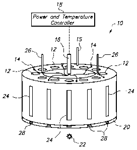
[0032] FIG. 1 is a perspective view of a carousel 10 of a thermal phase
simulator. The
carousel 10 has a plurality of wells 12 positioned therein and configured to
receive up to an equal
plurality of testing bottles (see FIG. 6). In the illustrated embodiment, the
carousel 10 has twelve
cylindrical wells 12 equally spaced along the circumference. Cartridge heating
elements 14 (six
shown) are inserted into the carousel 10 between every second well 12. There
is preferably at
least one thermocouple 15 for measuring the temperature of the block between
wells where there
is no heating element 14. This temperature indicates the extent to which the
entire block has
been heated. Another thermocouple is preferably associated with at least one
of the test bottles,
as described in reference to FIG. 4A, below. Both the heating elements 14 and
the
thermocouples 15 have wiring that extends through a wiring conduit 16 to a
power and
temperature controller 18. The controller 18 controls the temperature of the
carousel 10 and
permits the wells 12, along with the bottles and emulsion samples therein, to
be heated to a
temperature which will best simulate conditions in the field. The appropriate
temperature of the
fluids in the testing bottles will normally be in the range from about 100 C
to 160 C, so that the
water in the testing bottles will not generate pressures over 100 psig.
[0033] FIG. 1 also shows the carousel 10 mounted on an elevated, thermally
insulating,
slippery-surfaced stage 20 on a vertical axis such that the carousel 10 can be
rotated and the
bottle in each well 12 can be smoothly rotated in turn past fixed mixing or
observation points.
The stage 20 is connected to a light source 22 such that the light can be
directed behind and/or
below the bottle observation point. For example, gooseneck fiber optic
illuminators may be used.
However, one skilled in the art will understand that other illumination angles
and methods may
be used. In particular, the light source 22 may produce light in the
terahertz, infrared, near
infrared, visible, ultraviolet, and/or X-ray spectrum and can be of any design
known to those
7
CA 02827517 2013-08-15
WO 2012/161767 PCT/US2012/025662
skilled in the art. Thus, the slit 24 in the bottle well 12 allows observation
of the phase separation
process using not only the visible light spectrum, but also other portions of
the electromagnetic
spectrum that might be advantageous for imaging the fluids. Each slit 24
permits observation of
the effects that changing chemical agents, production fluids, diluents,
addition points, and other
operating conditions have on the phase separation. Optional underside
illumination ports 28
may be provided for illumination from the below the wells 12. The carousel 10
also has one or
more thermally isolated lifting handles 26 with which to turn the carousel on
the stage or remove
the carousel from the stage.
[0034] FIG. 2 is a bottom view of the carousel heating block 10 of FIG. 1.
The underside
illumination ports 28 are shown positioned below each well in the carousel. A
pivot shaft 30 is
provided in the axial center of the carousel 10 to keep the carousel on the
stage during rotation.
A mounting plate 32 is secured to the bottom of the carousel 10 to provide a
mechanical
connection to a tilt mechanism. For example, the tilt mechanism may include a
pair of brackets
34 secured to the mounting plate 32, including hinge points 36 and a hole 38
for a locking pin.
[0035] FIG. 3 is a schematic view of a bottle well 12 in the carousel of
FIG. 1. The bottle
well 12 includes an exterior viewing window 24, an interior illumination port
40, and an
underside illumination port 28. A test bottle 60 rests in the well 12 on a
rubber 0-ring 52 and is
held in place with a rubber-tipped leveraged latch 54 mounted on a top surface
55 of the
carousel. A preferred rubber composition is silicone. The carousel heater
block (i.e., the well 12)
and the latch 54 may also function as secondary containment devices in the
unlikely event that
the bottle 50 ruptures.
[0036] The carousel may be rotated so that the interior illumination port
40 is aligned with an
interior optic light source 41 and/or the underside illumination port 28 is
aligned with an
underside optic light source 43. With the carousel in this position, the
condition of the phases
within a particular bottle 60 may be easily visually observed. However, the
simulator preferably
includes an imaging device 44 that is aligned with the one or more light
source 41, 43. The
imaging device 44 may capture an image of the phases at a particular point in
time during a test.
By capturing such images at various times during the duration of a test, it is
possible to monitor
and analyze how one or more variables affect the phases. By capturing similar
images for each of
the bottles, it is possible to monitor, analyze and compare the performance of
one or more
chemical agents, one or more concentrations, and the like.
8
CA 02827517 2013-08-15
WO 2012/161767 PCT/US2012/025662
[0037] FIG. 4A is a schematic side view of a bottle 60 with a lid 64 having
a pressure relief
valve 68 and a septum port 66. The bottle cap 64 may be threadably coupled to
the bottle body
62 to seals a bottle cap 65 to the bottle lip 63 with an o-ring 66 there
between. The cap 65 is
fitted with a pressure relief valve 67 with a cracking pressure of 105 psig
and a burst pressure of
120 psig (half the burst strength of the bottle). This 105 psig pressure limit
allows water
temperatures up to 172 C to be used without boiling. The cap 65 also has a
septum port 68. The
cap 65 of at least one of the bottles 60 is also fitted with a thermocouple
probe 69 to measure the
fluid temperature of the bottle. The cap 65 may have a separate opening
dedicated to the
thermocouple probe, or the thermocouple probe may extend through the septum
port 68.
[0038] The septum port 68 may, for example, be a self-sealing septum port
rated to hold 105
psig. This allows chemicals and diluents to be added to the appropriate phase
and either oil or
mesophase emulsion to be selectively withdrawn with an appropriately gauged
syringe. Injecting
various fluids with different syringes eliminates dead volumes and cross
contamination relative
to using a permanent dip-tube.
[0039] FIG. 4B is a schematic side view of the bottle 60 with a cap 65
having a pressure
relief valve 67 and a sealed dip tube 70. The dip tube 70 may be sealed with a
compression seal
72. Other aspects of the bottle 60 and cap 65 are the same as in FIG. 4A.
[0040] The movable dip tube 70 can be raised or lowered to any desired
position in the
bottle. This allows chemicals and diluents to be added to the appropriate
phase and allows either
water, oil or mesophase emulsion to be selectively withdrawn in the manner of
the process being
simulated. A spring keeper is used to retain the dip tube should its
compression fitting become
loose. In one embodiment, the dip tube 70 is electrically isolated by using
non-conductive
fittings and insulating the exterior exposed metal. Polytetrafluoroethylene
(PTFE) or
polyetheretherketone (PEEK) are good materials for this insulation as well as
for the threaded
portion of the cap. The dip tube can then be connected to the high voltage
lead of a transformer
74. Electrically grounding the carousel 10 will then impose a radial electric
field across the oil
layer. To better focus this field, the length of the dip tube can be adjusted
to the thickness of the
oil layer. A voltage of 5 to 10 kV at 60 Hz is sufficient to oscillate the
water droplets in the oil to
destabilize the emulsion in the manner of full scale electric field assisted
coalescers. Frequencies
other than 60 Hz can also be used in the manner of some commercial coalescers.
A suitable
transformer available commercially is the 10kV, 23 mA, A10-LA2 model from
Dongan. Suitably
9
CA 02827517 2013-08-15
WO 2012/161767 PCT/US2012/025662
insulated high voltage leads and plug-in connectors for directing the voltage
to the dip tube 70
are also available commercially.
[0041] A testing bottle 60, especially the bottle body 62, may be made of
glass or other
substantially transparent material, such as quartz, diamond, sapphire or
clear, thermally stable
plastic. Transparent material is used to permit the operator to visually or
photographically
monitor the phase separation of the samples to obtain experiment results. It
is also desirable for
the bottle material to be electrically resistive to prevent any significant
electrical conduction in
the event an electric field is applied across the oil phase. If a multilayer
plastic is used, the inside
surface should be water wet to allow sheeting of droplets to the bottom.
[0042] The bottle walls are thick enough not to break under normal usage in
the thermal
phase separation simulator. Pressurization to about 100 psig is needed to test
water temperatures
up to 170 C without boiling. To provide a good margin for safety, the bottles
may have a burst
strength of at least 200 psig. A wall thickness of at least two millimeters of
borosilicate glass is
typically sufficient. The volume of the bottles can vary but the size and
shape must match up
with the bottle wells in the carousel 10. About 100 mL is generally
sufficient.
[0043] To assure bottle integrity and contaminant free surfaces, a new
bottle should be used
for each test rather than attempting to clean or reuse a bottle. The bottles
may be a mass-
produced, machine-formed, standard-threaded, bottle that is commercially
available at a cost
inexpensive enough to be disposable. Such a bottle was tested and found to
have a burst pressure
in excess of 240 psig.
[0044] FIG. 5 is a side view of a simulator 90 with the carousel 10 of FIG.
1 positioned
(axially) sideways in shaking mode on a shaker table 80, including a shaker 82
with a timer and
speed controller 84. The simulator may also include a fluid agitation or
mixing device.
[0045] The agitation device in FIG. 5 is a reciprocal shaker 82 with a
bracket 92 for
mounting the carousel 10 sideways, bottles horizontal (not shown), held in by
the latches (See
FIG. 3) to operate in a shaking mode. Alternatively, FIG. 6 places the
carousel 10 in an upright
viewing mode.
[0046] A reciprocal shaker preferably does not have a wrist or elbow action
arc to its throw
(as say a typical paint shaker does) since that would shake the top bottles
more than those on the
bottom. Preferably, the shaker 82 provides a means to vary the throw length
and/or frequency of
the shaking so that the severity of agitation can be controlled to replicate
the turbulence in the
CA 02827517 2013-08-15
WO 2012/161767 PCT/US2012/025662
flow lines, heat exchangers, static mixers, and separation vessels. A throw
distance of up to
about 8 cm and a frequency up to about 4/s (240 rpm) is generally sufficient.
The duration of
agitation is controlled by any conventional electronic device timer, such as
controller 84, suitable
for precision timing of the on/off switching of an electrical appliance. The
carousel 10 can
remain connected to power and temperature controller 18 (See FIG. 1) while
shaking, so that the
temperature can be maintained indefinitely, for however long the real mixing
process lasts.
[0047] Another embodiment uses one or more variable speed mixing or
stiffing devices
physically or magnetically coupled to a bar, blade, paddle or other mixing
element inside each
bottle. Mixing of the fluid may be done at a mixing station mounted at a fixed
position in the
stage. The bottles are mixed in sequence as the carousel is rotated past the
mixer. The bottles
then rotate past the observation point for images to be recorded a fixed time
after they were
mixed. In another embodiment, mixers are mounted under all the bottles wells
and fluids are
mixed while the fluids separate and images are recorded.
[0048] The simulator 90 includes a tilting mechanism that may be manually
or automatically
operated. As shown, the tilt mechanism includes a mounting bracket 92 and a
tilting bracket 94
coupled by a structural arm 96. Pivoting of the structural arm 96 relative to
the mounting bracket
92, and pivoting of the tilting bracket 94 relative to the structural arm 96
may be imparted by a
pneumatic cylinder or other know motive device. The title mechanism is
preferably design to
secure the entire carousel to the shaker table 80 and controllably move the
carousel 10 from the
shaking position of FIG. 5 to the viewing position of FIG. 6. The tilting
mechanism preferably
also includes a hole 95 in the tilting bracket 94, a hole 97 in the mounting
bracket 92, and a
locking pin 99. The locking pin 99 can be inserted into the holes 95, 97 when
the holes 95, 97
are aligned as in FIG. 6 in order to secure the carousel in either the
vertical or horizontal
position. Especially in the vertical position, the locking pin can prevent the
carousel from
unintentionally tipping over during the test.
[0049] FIG. 6 is a side view of the simulator 90 with the carousel 10 in an
upright position
above the shaker table. In this position, the carousel 10 may be rotated on
its axis for ease of
viewing the bottles, and positioning of the bottles adjacent an illumination
source, such as the
underside illumination source 43. In this position, each of the bottles is
vertically orientated,
such that the phases separate vertically with the axis of the bottles. The
slits 24 allow visual
observation, as well as the use of an imaging device or other types of devices
for measuring the
11
CA 02827517 2013-08-15
WO 2012/161767 PCT/US2012/025662
position or quality of the phases within the bottles. The holes 95, 97 are
preferably positioned so
that they align when the carousel 10 is in the viewing position of FIG. 6.
Accordingly, the
locking pin can be inserted into the holes to secure the carousel in this
position.
[0050] FIG. 7 is a screen shot illustrating an automated analysis of a
digital image 100 of the
fluid in the bottle of FIG. 3. In one embodiment, an imaging device is used to
record the
separation of the oil and water in the test bottles. With reference to FIG. 3,
the imaging device 44
may be a high resolution digital camera mounted in front of the illuminated
stage with the
imaging chip (e.g. charge coupled device or photomultiplier array) mapped to
the vertical swatch
of the bottle 60 that is visible through the slit 24. The imaging device can
be operated manually
or by using a controller synchronized to an automated carousel rotation to
record images at
desired time intervals, such that the operator need not be present during the
entire time necessary
to separate the emulsion. The data from the digital image is conveniently
processed through an
algorithm that computes the volume and the quality of the phases in the
bottle, as shown in the
screen shot of FIG. 7. Accordingly, photography and image analysis may be used
rather than
visual inspection to collect the data.
[0051] FIG. 8 is a schematic of an automated image collection system 110.
In the
embodiment shown, a data acquisition and control system 112 provides a control
signal to a
motor controller 114. The controller 114 then controls a three-phase gear
motor 116 that rotates
the carousel 10. The position of the carousel may be further detected and
indicated via a signal
118 back to the control system 112. When the carousel is positioned with a
selected bottle
aligned with the illumination stage, the control system 112 instructs a camera
44, using a macro
lens 120, to capture a digital image and send the resulting data to a
computer, such as a personal
computer 122. The computer 122 may receive input from a user via a keyboard
124 or other
input device. The computer may further produce an output 126, including a
camera imaging
profile and image morphology data.
[0052] The invention is also directed to a method of using the thermal
phase separation
simulator to select chemical agents for thermal phase separations. In one
embodiment, a fresh
emulsion, as found in the thermal phase separation system to be modeled, is
used, and the
amount of oil and water that separate from the emulsion as a function of time
is recorded to
calculate the separation rate. The residual contaminants still suspended in
each phase (oil and
12
CA 02827517 2013-08-15
WO 2012/161767 PCT/US2012/025662
solids in water, water and solids in oil) and the volume of condensed emulsion
"rag" between the
two phases is also recorded and converted to a numerical scale.
[0053] A faster separation in the batch test produces a narrower condensed
dispersion height
in the fluid flowing through the actual separation vessel, providing more
residence time to clean
up the free phases and making the interface level easier to control. Residual
contaminants set a
limit on the ultimate quality of the free phases produced, and residual rag
emulsion in the bottle
will build up in the separator over time.
[0054] In performing tests with fresh emulsion from a pressurized line, the
emulsion sample
should be taken with enough back pressure and cooling that it is not unduly
sheared or flashed
into a finer emulsion (shear or shock dispersion) or coarser emulsion (shear
coagulation) than
exists inside the line, as this is often irreversible. If the sample has two
free phases, these should
be separated in the sample and then recombined into each bottle for
consistency. If the sample is
actively separating, it should be kept stirred while being divided into each
test bottle.
[0055] The produced fluid sample should be taken from a point just before
the first chemical
addition that is being simulated. For each subsequent portion of the process
(e.g. flow line, heat
exchanger, diluent mixer, free water knockout, oil treater, or electric field
coalescer) key
conditions affecting the phase separation (e.g. temperature, turbulent flow
regime and linear
velocity, flow duration or residence time, chemical or diluent addition, free
water or oil removal,
electric field strength) should be recorded and emulated in the process
simulator. Accordingly,
the thermal phase separation simulator permits the operator to simulate these
useful parameters.
[0056] A typical procedure is as follows:
1. Add sample fluids and chemical treatments to bottles.
2. Seal bottles with cap assemblies.
3. Place bottle assemblies into wells in carousel and secure with latches.
4. Plug temperature controller into main power.
5. Adjust setpoint to 120 C, and let fluid temperature equilibrate to about
100 C.
6. Verify all bottles and fittings are pressure tight (no boiling).
7. Increase setpoint to maximum planned temperature, about 20 C above the
maximum
planned fluid temperature (<170 C), and let fluid temperature equilibrate
(about 60
minutes).
13
CA 02827517 2013-08-15
WO 2012/161767 PCT/US2012/025662
8.
Mount carousel on shaker and shake in a manner equivalent to the agitation the
fluid
would receive in the process for the full length of time it would receive it.
Examples:
a. Laminar flow, 1 cm/s: Select 60 rpm, 1 cm stroke
b. Turbulent flow, 2 cm/s: Select 120 rpm, 2 cm stroke
c. Turbulent flow, 20 cm/s: Select 240 rpm, 8 cm stroke
9. Return the carousel to the stage and rotate through the bottles to
record the fluid
separation.
10. At the appropriate time add additional chemical or diluent to the
bottles though the
septum with a gas-tight syringe.
11. After a length of time replicating that of the first process
separator, use a gas-tight
syringe to transfer the appropriate fluid phase through the septum into the
next
separator in series. For example, after replicating the free water knockout,
transfer the
oil phase to another bottle to simulate the oil treater, or the water phase to
another
bottle to simulate the skim tank.
12. Repeat the procedure on the transferred fluid, using parameters
appropriate to the next
separator.
[0057]
The terminology used herein is for the purpose of describing particular
embodiments
only and is not intended to be limiting of the invention. As used herein, the
singular forms "a",
"an" and "the" are intended to include the plural forms as well, unless the
context clearly
indicates otherwise. It will be further understood that the terms "comprises"
and/or
"comprising," when used in this specification, specify the presence of stated
features, integers,
steps, operations, elements, components and/or groups, but do not preclude the
presence or
addition of one or more other features, integers, steps, operations, elements,
components, and/or
groups thereof. The terms "preferably," "preferred," "prefer," "optionally,"
"may," and similar
terms are used to indicate that an item, condition or step being referred to
is an optional (not
required) feature of the invention. The corresponding structures, materials,
acts, and equivalents
of all means or steps plus function elements in the claims below are intended
to include any
structure, material, or act for performing the function in combination with
other claimed
elements as specifically claimed. The description of the present invention has
been presented for
purposes of illustration and description, but it not intended to be exhaustive
or limited to the
14
CA 02827517 2013-08-15
WO 2012/161767 PCT/US2012/025662
invention in the form disclosed. Many modifications and variations will be
apparent to those of
ordinary skill in the art without departing from the scope and spirit of the
invention. The
embodiment was chosen and described in order to best explain the principles of
the invention
and the practical application, and to enable others of ordinary skill in the
art to understand the
invention for various embodiments with various modifications as are suited to
the particular use
contemplated.