Note: Descriptions are shown in the official language in which they were submitted.
CA 02827663 2013-09-19
259323
ASYMMETRIC LOAD CONTROL FOR
TORSION FATIGUE REDUCTION IN A WIND TURBINE TOWER
FIELD OF THE INVENTION
[0001] The present invention relates generally to methods and systems for
controlling
wind turbines, and more particularly, to methods and systems for mitigating
asymmetric
loading of a wind turbine, thereby reducing torsional movement and/or
torsional loading
of a wind turbine tower.
BACKGROUND OF THE INVENTION
[0002] Wind power is considered one of the cleanest, most environmentally
friendly
energy sources presently available, and wind turbines have gained increased
attention in
this regard. A modern wind turbine typically includes a tower, generator,
gearbox,
nacelle, and one or more rotor blades. The rotor blades capture kinetic energy
of wind
using known airfoil principles. The rotor blades transmit the kinetic energy
in the form
of rotational energy so as to turn a shaft coupling the rotor blades to a
gearbox, or if a
gearbox is not used, directly to the generator. The generator then converts
the
mechanical energy to electrical energy that may be deployed to a utility grid.
[0003] Vertical and horizontal wind shears, yaw misalignment, and/or wind
turbulence may act either collectively or individually for producing an
asymmetric
loading of the wind turbine. In particular, such an asymmetric loading may act
across the
wind turbine rotor. As a result, at least some elements of the wind turbine
may be
deformed. For example, the main shaft of the wind turbine may be bent (e.g.,
radially
displaced) as a result of asymmetric rotor loading.
[0004] In order to mitigate the effect of the asymmetric loading of a wind
turbine,
conventional asymmetric load control (ALC) systems may use an array of
sensors, such
as proximity sensors, in the wind turbine to directly measure deformation of
at least some
elements of the wind turbine, such as a bending of the main shaft as described
for
example in U.S. Pat. No. 7,160,083 entitled Method and Apparatus for Wind
Turbine
1
CA 02827663 2013-09-19
259323
Rotor Load Control. Further, a set of sensors for ALC may be provided in the
yaw
system to directly measure a yaw drive signal, such as described in U.S. Pat.
Application
No. 2012/0027589 entitled Method and Apparatus for Control of Asymmetric
Loading of
a Wind Turbine. In each instance, the ALC system uses signals generated by the
ALC
sensors for mitigating the effect of an asymmetric load of the rotor by, for
example,
controlling blade pitch and/or yaw alignment of the wind turbine. Accordingly,
an ALC
assembly may facilitate with reducing the effects of extreme loads and fatigue
cycles
acting on the wind turbine.
[0005] Current ALC assemblies, however, are only configured for detecting a
limited
number of deflections (i.e. main shaft deflection, fore-aft and side-side
tower movement,
and a yaw drive deflection), though new developments in tower technology have
created
a need for detecting additional loading parameters. For example, lattice tower
structures,
also known as space frame structures, utilize a highly engineered and
optimized structure
capable of handling unique static and dynamic loads that occur during wind
turbine
operation. Such tower structures, however, have generally lower torsional
stiffness and
frequencies. These characteristics greatly influence design costs and may make
the tower
more susceptible to twisting due to torsional loads that may frequently occur
from
asymmetric rotor loading. It would therefore be desirable to detect torsional
movement
and/or torsional loading in the tower before fatigue and extreme torsion
occurs, thereby
increasing the life of the tower.
[0006] Thus, an improved method and system for further reducing asymmetric
loading and/or increasing the reliability of current ALC assemblies is
desirable.
Accordingly, a method and system for detecting and reducing torsional movement
and/or
torsional loading of a wind turbine tower would be advantageous.
BRIEF DESCRIPTION OF THE INVENTION
[0007] Aspects and advantages of the invention will be set forth in part in
the
following description, or may be obvious from the description, or may be
learned through
practice of the invention.
2
CA 02827663 2013-09-19
259323
[0008] In one embodiment, a wind turbine according to the present invention
is
disclosed. The wind turbine includes a tower, a nacelle configured atop the
tower, a rotor
having a rotatable hub connected to a main shaft and at least one rotor blade,
a tower
torsion detection system operably configured to generate a tower torsion
signal, and an
asymmetric load control assembly. The tower torsion signal may correspond to
an actual
torsional movement of the tower or a torsional loading of the tower that may
or may not
be inducing actual torsional movement. Further, the asymmetric load control
assembly is
in communication with the tower torsion detection system to receive the tower
torsion
signal and to mitigate an asymmetric load acting on the wind turbine using the
tower
torsion signal.
[0009] In another embodiment, the tower torsion detection system may
include a
plurality of sensors circumferentially spaced relative to the tower to detect
torsional
movement and/or torsional loading of the tower. Further, the tower torsion
detection
system may generate a tower torsion signal based on the torsional movement
and/or
torsional loading. In additional embodiments, the wind turbine may include at
least three
sensors circumferentially spaced apart in a common, generally horizontal plane
around
the tower so as to detect a torsional movement and/or torsional loading of the
tower. The
sensors may be accelerometers, pressure sensors, strain gauges, or any
combination
thereof.
[0010] In yet another embodiment, the wind turbine may include a rotor
blade pitch
control system. The asymmetric load control assembly may be in communication
with
the pitch control system to mitigate the asymmetric load acting on the rotor
by altering a
pitch angle of the rotor blade. In still additional embodiments, the
asymmetric load
control assembly may be configured to mitigate the asymmetric load based
directly on the
tower torsion signal.
[0011] In additional embodiments, the asymmetric load control assembly may
further
include a sensor configured to directly or indirectly detect bending of the
main shaft due
to asymmetric loading of the rotor and may generate a corresponding asymmetric
load
3
CA 02827663 2013-09-19
259323
signal. Further, the asymmetric load control assembly may be configured to
mitigate the
asymmetric load using the asymmetric load signal and the tower torsion signal.
Additionally, the asymmetric load control assembly may be further configured
to mitigate
the asymmetric load directly based on the asymmetric load signal and use the
tower
torsion signal for validating the asymmetric load signal.
[0012] In still another embodiment, a method for operating a wind turbine
is
disclosed. The method includes: generating a tower torsion signal
corresponding to an
actual torsional movement of the tower or a torsional loading of the tower;
and,
mitigating an asymmetric load acting on the wind turbine using the tower
torsion signal.
[0013] In additional embodiments, the method may further include mitigating
the
asymmetric load by altering the pitch angle of at least one rotor blade.
Further, the
method may include mitigating the asymmetric load directly based on the tower
torsion
signal. In still additional embodiments, the method may further comprise
directly or
indirectly detecting bending of the main shaft due to asymmetric loading of
the rotor and
generating a corresponding asymmetric load signal, wherein the asymmetric load
is
mitigated using the asymmetric load signal and the tower torsion signal.
[0014] In yet another embodiment, a control system for a wind turbine is
disclosed.
The control system includes an asymmetric load control assembly configured to
receive a
tower torsion signal and mitigate an asymmetric load acting on the rotor using
the tower
torsion signal. The tower torsion signal may correspond to an actual torsional
movement
of the tower or a torsional loading of the tower. Further, the control system
may be
configured to adjust a pitch angle of at least one rotor blade of the wind
turbine so as to
reduce the asymmetric load acting on the rotor. In still further embodiments,
the
asymmetric load control assembly may further include a sensor configured to
directly or
indirectly detect bending of the main shaft due to asymmetric loading of the
rotor, and to
generate a corresponding asymmetric load signal. It should be understood that
the
asymmetric load control assembly of the control system may further include all
the
limitations described herein.
4
CA 02827663 2013-09-19
259323
[0015] These and other features, aspects and advantages of the present
invention will
become better understood with reference to the following description and
appended
claims. The accompanying drawings, which are incorporated in and constitute a
part of
this specification, illustrate the embodiments of the invention and, together
with the
description, serve to explain the principles of the invention.
BRIEF DESCRIPTION OF THE DRAWINGS
[0016] A full and enabling disclosure of the present invention, including
the best
mode thereof, directed to one of ordinary skill in the art, is set forth in
the specification,
which makes reference to the appended figures, in which:
[0017] FIG. 1 illustrates a perspective view of one embodiment of a wind
turbine
according to the present disclosure;
[0018] FIG. 2 illustrates a perspective view of one embodiment of a nacelle
configured atop a tower of a wind turbine according to the present disclosure;
[0019] FIG. 3 illustrates a perspective view of one embodiment of a wind
turbine
tower having a lattice structure according to the present disclosure;
[0020] FIG. 4 illustrates another perspective view of one embodiment of a
wind
turbine tower having a lattice structure according to the present disclosure;
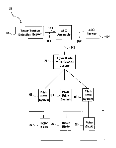
[0021] FIG. 5 illustrates a block diagram of a control system for
controlling the wind
turbine according the present disclosure; and
[0022] FIG. 6 illustrates a flow chart of a method for detecting and
reducing a
torsional movement and/or torsional loading of a tower of a wind turbine
according to the
present disclosure.
DETAILED DESCRIPTION OF THE INVENTION
[0023] Reference now will be made in detail to embodiments of the
invention, one or
more examples of which are illustrated in the drawings. Each example is
provided by
CA 02827663 2013-09-19
259323
way of explanation of the invention, not limitation of the invention. In fact,
it will be
apparent to those skilled in the art that various modifications and variations
can be made
in the present invention without departing from the scope or spirit of the
invention. For
instance, features illustrated or described as part of one embodiment can be
used with
another embodiment to yield a still further embodiment. Thus, it is intended
that the
present invention covers such modifications and variations as come within the
scope of
the appended claims and their equivalents.
[0024] As mentioned above, vertical and horizontal wind shears, yaw
misalignment,
and/or turbulence may act individually or together to produce asymmetric
loading across
a wind turbine rotor. The resultant asymmetric load produces a bending moment
in the
rotor blades that are reacted through the hub and subsequently to other wind
turbine
components. Such asymmetric loading may cause deformations of elements in the
wind
turbine, including, for example, bending or radial displacement of the main
shaft or a
torsional movement and/or torsional loading of the tower. More specifically,
torsional
movement and/or torsional loading of a wind turbine tower may exist more
frequently in
lattice tower structures. Such structures may have relatively low torsional
stiffness and
frequencies (as compared to tubular tower structures), wherein the tower may
be more
susceptible to twisting or torsional deformation. A "torsional movement" is
used herein
to refer to any torsional deformation, including twisting or rotational
movement relative
to the vertical axis of a wind turbine tower.
[0025] The embodiments described herein facilitate reducing asymmetric
loading
acting on the rotor of a wind turbine, thereby reducing torsional loading
and/or torsional
movement of the tower and deformations of the main shaft. Further, embodiments
herein
may increase reliability of asymmetric load control (ALC) of a wind turbine.
[0026] In particular, a wind turbine including a tower, a nacelle, a rotor
having a
rotatable hub connected to a main shaft and at least one rotor blade, a tower
torsion
detection system operably configured to generate a tower torsion signal, and
an
asymmetric load control assembly is disclosed. The tower torsion signal may
correspond
6
CA 02827663 2013-09-19
259323
to an actual torsional movement of the tower or a torsional loading of the
tower. Further,
the asymmetric load control assembly is in communication with the tower
torsion
detection system to receive the tower torsion signal. Moreover, the asymmetric
load
control assembly is further configured to mitigate an asymmetric load acting
on the wind
turbine using the tower torsion signal.
[0027] The asymmetric load control assembly (hereinafter referred to as the
ALC
assembly) is configured for receiving a tower torsion signal generated by a
tower torsion
detection system. The tower torsion signal may then be used to determine the
magnitude
and/or the orientation of the resultant rotor load. The ALC assembly may then
use the
tower torsion signal in any type of open or closed loop feedback control
scheme for
mitigating an asymmetric load. Mitigating asymmetric loads may include
reducing or
countering asymmetric rotor loading. Thereby, the ALC assembly is configured
for
causing a more symmetric load on the rotor. The ALC assembly may mitigate the
asymmetric load by adequately pitching the blades of the wind turbine.
[0028] Further, the ALC assembly may mitigate the asymmetric loads directly
based
on the tower torsion signal. In other words, the torsion signal is the primary
signal that is
measured and corrected for in subsequent control/corrective actions. For
example, the
ALC assembly may implement a control scheme configured to produce a control
signal
based on the tower torsion signal for reducing the asymmetric loads (discussed
further in
regards to FIG. 5 below) as reflected by a change (e.g., reduction) of the
tower torsion
signal. Alternatively, or in addition thereto, the wind turbine may implement
an ALC
sensor for directly sensing asymmetric loads acting on the rotor. In such
embodiments,
the ALC assembly may mitigate the asymmetric loads directly based on the
measurements of the ALC sensor and use the tower torsion signal for validating
the
measurements. Thereby, embodiments herein may facilitate increasing
reliability of ALC
of the wind turbine.
[0029] In a wind turbine implementing an ALC sensor, the tower torsion
signal may
also be used for redundancy purposes in the instance of ALC sensor failure.
Further, the
7
CA 02827663 2013-09-19
259323
tower torsion signal may also be used in combination with the measurements of
the ALC
sensor for generating an ALC signal.
[0030] Referring now to the figures, FIG. 1 is a perspective view of an
exemplary
wind turbine 10. In the exemplary embodiment, the wind turbine 10 is a
horizontal-axis
wind turbine. Further, the wind turbine 10 includes a tower 12 that extends
from a
support system 14, a nacelle 16 mounted on tower 12, and a rotor 18 that is
coupled to
nacelle 16. The rotor 18 includes a rotatable hub 20 connected to a main shaft
(not
shown) and at least one rotor blade 22 coupled to and extending outward from
hub 20. In
the exemplary embodiment, rotor 18 has three rotor blades 22. In an
alternative
embodiment, rotor 18 may include more or less than three rotor blades 22.
[0031] Rotor blades 22 are spaced about hub 20 to facilitate rotation of
the rotor 18 to
enable kinetic energy to be transferred from the wind into usable mechanical
energy, and
subsequently, electrical energy. The rotor blades 22 may be mated to the hub
20 by
coupling a blade root portion 24 to the hub 20 at a plurality of load transfer
regions 26.
Load transfer regions 26 have a hub load transfer region and a blade load
transfer region
(both not shown in FIG. 1). Loads induced to rotor blades 22 are transferred
to the hub
20 via load transfer regions 26.
[0032] The rotor blades 22 may have any suitable length that enables the
wind turbine
to function as described herein. As wind strikes the rotor blades 22 from a
direction
28, the rotor 18 is rotated about an axis of rotation 30. As the rotor blades
22 are rotated
and subjected to centrifugal forces, they are also subjected to various forces
and
moments. As such, the rotor blades 22 may deflect and/or rotate from a
neutral, or non-
deflected, position to a deflected position.
[0033] Moreover, a pitch angle or blade pitch of rotor blades 22 (i.e., an
angle that
determines the perspective of the rotor blades 22 with respect to direction 28
of the
wind), may be changed by a rotor blade pitch control system 32 to control the
load and
power generated by the wind turbine 10. For example, during operation of wind
turbine
8
CA 02827663 2013-09-19
259323
10, the blade pitch control system 32 may rotate the pitch of the rotor blades
22 about
pitch axes 34, such that the rotor blades 22 are moved to a feathered
position, which
facilitates reducing a rotational speed of the rotor 18 and/or facilitates a
stall of the rotor
18. In an exemplary embodiment, the pitch of each rotor blade 22 is controlled
individually by a control system 25 (FIG. 2). Alternatively, the pitch for all
rotor blades
22 may be controlled simultaneously by control system 25.
[0034] Referring now to FIG. 2, an enlarged sectional view of a portion of
a nacelle
16 atop a tower 12 of a wind turbine 10 is illustrated. In the exemplary
embodiment, the
wind turbine 10 includes a nacelle 16 and a rotor 18. The rotor 18 includes
hub 20
rotatably coupled to the nacelle 16. More specifically, the hub 20 is
rotatably coupled to
an electric generator 42 positioned within nacelle 16 by rotor shaft 39 (also
referred to as
either a main shaft or a low speed shaft), a gearbox 38, a high speed shaft
48, and a
coupling 36. In an exemplary embodiment, the rotor shaft 39 is disposed
coaxial to
longitudinal axis 116. Rotation of the main shaft 39 drives the gearbox 38
that
subsequently drives the high speed shaft 48. The high speed shaft 48 drives
the generator
42 with the coupling 36. Further, rotation of the high speed shaft 48
facilitates
production of electrical power by the generator 42. The gearbox 38 and
generator 42 are
supported by a supports 52, 54.
[0035] Still referring to FIG. 2, the wind turbine 10 includes a tower
torsion detection
system 92, as indicated by the dotted lines. The tower torsion detection
system 92 may
include sensors 37 located in any suitable location on or near the tower 12 so
as to infer a
torsional movement and/or torsional loading of the tower. For example, as
illustrated, the
sensors 37 are circumferentially spaced relative to the tower 12. More
specifically, the
sensors 37 are circumferentially spaced apart in a common, generally
horizontal plane
around the tower so as to detect torsional movement and/or torsional loading
of the tower
12. For example, a torsional signal of generally equal magnitude sensed on the
plurality
of sensors 37 disposed in a common horizontal plane is an indicator of
torsional
distortion as compared to a bending of the tower in a side-to-side or back-to
front
9
CA 02827663 2013-09-19
259323
direction. In other embodiments, the sensors 37 may be located on, near, or
within the
tower 12 or the nacelle 16, or any combination thereof. The sensors 37 may
also be
located in the yaw system 50. For example, the sensors 37 may be located
between the
pinion and rack in the yaw gears 44 (not shown).
[0036] In one embodiment, any number of sensors 37 may be employed to
detect a
torsional movement and/or torsional loading of the tower 12. For example, as
illustrated
in FIG. 2, there are three sensors 37. In other embodiments, more than three
sensors may
be employed. In still additional embodiments, less than three sensors may be
employed.
[0037] Additionally, the tower torsion detection system 92 may include any
suitable
type of sensor capable of inferring a torsional loading and/or movement of the
tower 12.
For example, in one embodiment, the sensors may be a triad of accelerometers
circumferentially spaced relative to the tower so as to detect torsional
movement and/or
torsional loading of the tower. In additional embodiments, the sensors 37 may
be inertial
measurement unit (IMU) sensors or miniature inertial measurement unit (MIMU)
sensors.
In still additional embodiments, pressure sensors may be employed, such as in
the yaw
system 50 between the pinion and rack (not shown) in the yaw gears 44. In
still
additional embodiments, the sensors 37 may be strain gauges. It should be
understood
that any combination of sensors mentioned herein or other suitable sensor may
be
employed in the present invention.
[0038] Moreover, the tower torsion detection system 92 is not limited to
using
sensors, but may include any suitable means for measuring a torsional movement
and/or
torsional loading of the tower 12. Further, it should be understood that the
tower torsion
detection system 92 may include any suitable means for reducing a torsional
loading
and/or movement of the tower 12. For example, the means for reducing torsional
movement and/or torsional loading of the tower may also include varying the
orientation
of the nacelle 16 in relation to the wind direction 28.
CA 02827663 2013-09-19
259323
[0039] Still referring to FIG. 2, the hub 20 may further include a pitch
assembly 66.
Pitch assembly 66 may include a rotor blade pitch control system 73
operatively coupled
to one or more pitch drive systems 68. Each pitch drive system 68 is coupled
to a
respective rotor blade 22 (shown in FIG. 1) for altering the pitch of the
associated rotor
blade 22 along pitch axis 34. Only one of three pitch drive systems 68 is
shown in FIG.
2. It should be understood that the blade pitch control system 73 may be a
centralized
controller associated to a plurality of pitch drive systems 68, such as shown
in FIG. 5.
Alternatively, the wind turbine 10 may include a distributed blade pitch
control system 73
including, for example, a plurality of blade pitch control systems, each being
associated
to a respective pitch drive system 68.
[0040] In the exemplary embodiment, the pitch assembly 66 includes at least
one
pitch bearing 72 coupled to hub 20 and to the respective rotor blade 22.
Further, the pitch
drive system 68 includes a pitch drive motor 74, a pitch drive gearbox 76, and
a pitch
drive pinion 78. The pitch drive motor 74 is coupled to the pitch drive
gearbox 76 such
that the pitch drive motor 74 imparts mechanical force to the pitch drive
gearbox 76. The
pitch drive gearbox 76 is coupled to the pitch drive pinion 78 such that the
pitch drive
pinion 78 is rotated by the pitch drive gearbox 76. The pitch bearing 72 is
coupled to the
pitch drive pinion 78 such that the rotation of the pitch drive pinion 78
causes rotation of
the pitch bearing 72. More specifically, the pitch drive pinion 78 is coupled
to the pitch
bearing 72 such that rotation of the pitch drive gearbox 76 rotates the pitch
bearing 72
and the rotor blade 22 about the pitch axis 34 so as to change the pitch of
the rotor blade
22.
[0041] The pitch drive system 68 may be coupled to the control system 25
for
adjusting the pitch of the rotor blade 22 upon receipt of one or more signals
from the
control system 25. The pitch drive motor 74 may be any suitable motor driven
by
electrical power, pneumatic system and/or a hydraulic system that enables the
pitch
assembly 66 to function as described herein. Alternatively, the pitch assembly
66 may
include any suitable structure, configuration, arrangement, and/or components
such as,
11
CA 02827663 2013-09-19
259323
but not limited to, hydraulic cylinders, springs, and/or servo-mechanisms.
Moreover, the
pitch assembly 66 may be driven by any suitable means such as, but not limited
to,
hydraulic fluid, and/or mechanical power, such as, but not limited to, induced
spring
forces and/or electromagnetic forces.
[0042] As mentioned previously, the wind turbine 10 may also include a yaw
system
50 that may be used to rotate nacelle 16 and hub 20 about yaw axis 38 (shown
in FIG. 1).
The yaw system 50 may be placed at the joint between the tower 12 and the
nacelle 16.
Further, the yaw system 50 may collaborate with a yaw drive mechanism 32 for
rotating
the nacelle 16. Each yaw drive mechanism 32 may include a yaw motor 64 coupled
to a
yaw gear 44 configured to engage the yaw bearing 51.
[0043] Referring now to FIGS. 1, 3, and 4, the tower 12 of the present
invention may
be fabricated from tubular steel that extends between the support system 14
and the
nacelle 16, as shown in FIG. 1. In an exemplary embodiment, the tower 12 may
be
fabricated from a lattice structure as shown in FIGS. 3 and 4. Lattice tower
structures
utilize a highly engineered and optimized structure capable of handling unique
static and
dynamic loads that occur during wind turbine operation. As illustrated, each
wind turbine
having a lattice tower structure 13 includes a rotor 18 having a plurality of
rotor blades
22 mounted to a hub 20. The rotor 18 is coupled to the nacelle 16, which is
supported
atop the tower 12.
[0044] The lattice tower structure 13 is formed by vertically oriented legs
15,
horizontal braces 17, and diagonal braces 19. The legs 15 are typically angle
iron
members or pipe members, and the braces 17, 19 are typically angle iron
members. As
mentioned, these lattice tower structures 13 are also referred to in the art
as space frame
towers. The lattice tower structure 13 may be fabricated in sections and
erected at the
wind turbine site. In the embodiment of FIG. 3, a cladding material 21 is
applied over the
lattice structure, which may be any type of suitable fabric, such as an
architectural fabric
designed for harsh weather conditions. The cladding 21 protects workers and
equipment
within the tower and provides an aesthetic appearance to the wind turbine 10.
12
CA 02827663 2013-09-19
259323
[0045] Though lattice tower structures offer many benefits as described
herein, they
may have low torsional stiffness and frequencies. As mentioned, such
characteristics
greatly influence design costs and may make the tower more susceptible to
twisting due
to torsional loading that may frequently occur due to asymmetric rotor
loading. The
present invention, therefore, is capable of detecting a torsional movement
and/or torsional
loading of these lattice structures before fatigue and extreme torsion occurs,
thereby
increasing the life of the tower.
[0046] Referring now to FIG. 5, a block diagram of a control system 25 for
controlling the wind turbine 10 is illustrated. The control system 25 may
implement a
number of control actions, including, but not limited to, yaw control, ALC
pitch control,
and management of ALC sensors. The exemplary system 25 includes the ALC
assembly
100 configured to receive a tower torsion signal 101 generated by the tower
torsion
detection system 92 and mitigate an asymmetric load acting on the wind turbine
rotor.
[0047] Optionally, the ALC assembly 100 may be operatively connected to one
or
more ALC sensors 134. The ALC sensors 134 may be configured to receive signals
corresponding to direct measurements of effects caused by an asymmetric rotor
loading
such as, but not limited to, a bending or radial displacement of the main
shaft 39 (FIG. 2).
More specifically, the ALC sensor 134 may be a proximity sensor that measures
displacement or strain of the shaft 39 using sensor technologies based on
acoustic,
optical, magnetic, capacitive or inductive field effects. In FIG. 5, only one
sensor 134 is
illustrated, though it should be understood that a plurality of sensors may
also be
employed to measure displacement of the main shaft 39 caused by an asymmetric
load.
[0048] The ALC assembly 100 may analyze the tower torsion signal 101 and/or
the
ALC signal 102 to determine an asymmetric load acting on rotor 18. The tower
torsion
signal 101 may correspond to an actual torsional movement or a torsional
loading of the
tower 12. The ALC assembly 100 will then generate information for mitigating
the
asymmetric load. Alternatively or in addition thereto, the ALC assembly 100
may use
one of these signals for validating a reference signal used for ALC or as a
redundant data.
13
CA 02827663 2013-09-19
259323
Further, the ALC assembly 100 may be configured to generate an ALC signal
based on
the received signal(s) for mitigating an asymmetric loading.
[0049] According to the exemplary scheme of FIG. 5, and other embodiments
described herein, the ALC assembly 100 is operatively connected to a rotor
blade pitch
control system 73 configured to alter the pitch of at least one of the rotor
blades 22. The
blade pitch control system 73 receives the ALC assembly signal 103 and, based
on this
signal 103, operates at least one of the pitch drive systems 68 for mitigating
an
asymmetric loading acting on the rotor 18.
[0050] According to at least some embodiments herein, the ALC assembly 100
is
configured to mitigate an asymmetric load directly based on a tower torsion
signal 101.
That is, the ALC assembly 100 may be configured for determining an ALC
assembly
signal 103 facilitating mitigation of an asymmetric rotor loading directly
based on the
reference data contained in the tower torsion signal 101. Thereby, ALC may be
implemented using information generated by the tower torsion detection system
92. The
tower torsion signal 101 is typically suitable for directly implementing ALC
since the
signal 101 typically provides information, which can be correlated to a
torsional
movement and/or torsional loading of the tower 12 caused by an asymmetric load
of the
wind turbine 10. Further, the tower torsion signal 101 may be generated in
analog and/or
digital format.
[0051] As set forth above, the ALC assembly 100 may be configured to
mitigate an
asymmetric rotor loading by pitching at least one of the rotor blades 22. In
particular, the
tower torsion signal 101 and/or the ALC signal 102 may be used to determine a
pitch for
each of the rotor blades 22. For example, the tower torsion signal 101 may be
used to
estimate a torsional movement and/or torsional loading and, thereby, the
magnitude
and/or phase angle of asymmetric rotor loading. The estimated magnitude and/or
phase
angle can then be used to determine a blade pitch for at least one of rotor
blades 22 to
reduce the asymmetric rotor loading. The pitch may be determined using
information
14
CA 02827663 2013-09-19
259323
solely from the tower torsion signal 101 or from both the tower torsion signal
101 and the
ALC signal 102.
[0052] In an exemplary embodiment, the tower torsion detection system 92
typically
provides a tower torsion signal 101 having a high quality. Thereby,
reliability of ALC
may be further improved by using the tower torsion signal 101 for mitigating
an
asymmetric rotor loading. For example, the ALC assembly 100 may be configured
to
mitigate an asymmetric load using a tower torsion signal 101 generated by the
tower
torsion detection system 92 and an ALC signal 102 generated by the ALC
sensor(s) 134.
Thereby, reliability of ALC may be increased. Additionally, in some
embodiments, the
ALC assembly 100 is configured to 1) perform ALC based on the signal provided
by
ALC sensors and 2) use the tower torsion signal 101 for evaluating and/or
validating
performance of the ALC sensor(s) 134. According to other embodiments, the ALC
assembly 100 is configured to use the tower torsion signal 101 only as a
redundant signal
in the instance of ALC sensor failure. Further, the ALC assembly 100 may be
configured
to mitigate an asymmetric load based on the combination of the ALC signal 102
and the
tower torsion signal 101.
[0053] FIG. 2 illustrates the control system 25 as being centralized within
the nacelle
16, however, the control system 25 may be a distributed system throughout wind
turbine
10, on support system 14, within a wind farm, and/or at a remote control
center. Further,
the control system 25 typically includes a processor (not shown) configured to
perform
the methods and/or steps described herein. As used herein, the term
"processor" broadly
refers to a controller, a microcontroller, a microcomputer, a programmable
logic
controller (PLC), a field programmable gate array (FPGA), an application
specific
integrated circuit, and other programmable circuits. Further, these terms may
be used
interchangeably herein.
[0054] Additionally, it should be understood that the control system 25 may
also
include memory, input channels, and/or output channels. In the embodiments
described
herein, memory may include, without limitation, a computer-readable medium,
such as a
CA 02827663 2013-09-19
259323
random access memory (RAM), and a computer-readable non-volatile medium, such
as
flash memory. Alternatively, a floppy disk, a compact disc-read only memory
(CD-
ROM), a magneto-optical disk (MOD), and/or a digital versatile disc (DVD) may
also be
used. Also, in the embodiments described herein, input channels include,
without
limitation, sensors and/or computer peripherals associated with an operator
interface,
such as a mouse and a keyboard. Further, in the exemplary embodiment, output
channels
may include, without limitation, a control device, an operator interface
monitor and/or a
display.
[0055] In the exemplary embodiment, the control system 25 may include a
real-time
controller having any suitable processor-based or microprocessor-based system,
such as a
computer system, that includes microcontrollers, reduced instruction set
circuits (RISC),
application-specific integrated circuits (ASICs), logic circuits, and/or any
other circuit or
processor that is capable of executing the functions described herein. In one
embodiment, the controller may be a microprocessor that includes read-only
memory
(ROM) and/or random access memory (RAM), such as, for example, a 32 bit
microcomputer with 2 Mbit ROM, and 64 Kbit RAM.
[0056] Referring now to FIG. 6, a flow chart of an exemplary method 600 of
operating the wind turbine 10 is illustrated. Method 600 may include
generating 610 one
or more tower torsion signal(s) appropriate for being used for ALC of the wind
turbine
10. According to embodiments herein, the tower torsion signal is generated by
the tower
torsion detection system 92, as described above. According to at least some
embodiments described herein, an ALC signal may be generated by the ALC sensor
134
in addition to the tower torsion signal.
[0057] Method 600 may further include receiving 620 the tower torsion
signal and
optionally, the ALC signal, generated by the ALC sensor. Typically, these
signals are
received by the ALC assembly 100. Further, the components of the ALC assembly
100
receiving the signals (e.g., a processor or an analog to digital converter)
are coupled to
the elements of the wind turbine 10 used for detecting an asymmetric load
(e.g., tower
16
CA 02827663 2013-09-19
259323
torsion detection system 92 and/or ALC sensor 134). The ALC assembly 100 may
convert these signals to a usable format, if required. Method 600 further
includes
mitigating 630 an asymmetric load acting on the rotor 18 using the signals for
ALC,
namely the tower torsion signal and, optionally, the ALC signal.
[0058] Mitigating 630 the asymmetric load may further include a step 632
for
determining the effects (e.g., loads) caused on one or more components of the
wind
turbine 10 by an asymmetric load of the rotor 18 using the signals for ALC.
For example,
the control system 25 may use any suitable means to convert the input data to
relevant
asymmetric load data (e.g., a torsional loading and/or torsional movement of
the tower
and a main shaft deflection). Step 632 may also include determining the load
on the rotor
blades 22 as well as any properties of an asymmetric rotor loading.
[0059] Mitigating 630 the asymmetric load may also include a step 634 for
determining a response to reduce or counter the asymmetric rotor loading. For
example,
in response to a particular asymmetric rotor loading, the control system 25
may determine
that the response should be to change the pitch of one or more rotor blades
22. As
another example, the determined response may be applying a brake to stop or
slow
rotation of the hub 20.
[0060] Mitigating 630 the asymmetric load may additionally include a step
636 for
generating a signal that enables responding to the asymmetric load. For
example, a
response signal may be generated in the form of, for example, a set of control
signals
transmitted over individual control lines, to cause the blade pitch control
system 73 to
change the pitch of one or more of the rotor blades 22. If the selected
response fails to
cause the wind turbine 10 to operate within an acceptable operating range,
method 600
can be repeated as often as necessary or even discontinued, resulting in a
pitch control
without the benefits of the described ALC algorithm(s).
[0061] While there have been described herein what are considered to be
preferred
and exemplary embodiments of the present invention, other modifications of
these
17
CA 02827663 2013-09-19
259323
embodiments falling within the invention described herein shall be apparent to
those
skilled in the art.
18