Note: Descriptions are shown in the official language in which they were submitted.
CA 02828375 2013-08-27
WO 2012/118487
PCT/US2011/026643
Attorney Docket No: 8953-00-WO-TB
TOOTHBRUSH INCLUDING A DEVICE FOR INDICATING BRUSHING FORCE
FIELD OF THE INVENTION
100011 The present invention relates to a toothbrush, and in particular to a
toothbrush which
incorporates a device to indicate to the user that a suitable force is being
applied during
brushing.
BACKGROUND
[0002] It is widely appreciated that people cause serious damage to their
teeth and gums by
brushing too hard, and there have been a number of designs of toothbrush aimed
at
overcoming this problem. Several studies have arrived at the conclusion that
excessive force
during brushing leads to recession on premolars, and also gingival recession,
which exposes
the underlying cementum, often leading to hypersensitivity, loss of
aesthetics, and may be a
factor in root caries and root surface abrasion, leading to root fillings.
[0003] One solution is a brush, which simply will not transmit excessive
force, for example a
design disclosed in DE 3724476 where the neck of the toothbrush buckles if the
user attempts
to brush too hard. This, however, may result in a relatively flimsy product,
which may be
frustrating to use, as brushing may continually be interrupted.
[0004] Another known solution is disclosed in US 5502861, which provides a
toothbrush
with an indicator which signals to the user if excessive force is being
applied. This has the
advantage that the user is provided with a clear signal that brushing is too
hard, and which
can be used to learn to brush correctly. It is disclosed in US 5282291 that it
is thought
preferable to make the indicator mechanism an integral part of the brush,
rather than an
attachment to it; the latter arrangement generally results in a brush which is
awkwardly
shaped and unnatural to use.
[0005] Designs incorporating integral indicators, which are activated by
electrical circuits,
are known. In the design disclosed in US 5282291, components of the circuit
are brought
into contact as the brush flexes, completing the circuit and triggering the
indicator. Often, the
user must fit a battery to power the indicator, which due to the limited size
of the brush must
be small and is, therefore, tricky to fit. In designs where a battery is
required, access to the
circuitry must be available, for example through a removable cover. This
arrangement is
inevitably less hygienic: the cover is unlikely to fit exactly flush with the
handle surface and
debris may collect in any gap between the cover and handle and also in the
cavity itself. The
1
CA 02828375 2015-01-21
62301-3347
device disclosed in DE 3724476 avoids the problem of powering the indicator
circuit by
relying instead on a piezoelectric component to act as a mechanical-electrical
converter
producing an electrical signal in response to the applied force. Obviously,
these designs
require a number of miniature components fitted into a small cavity in the
brush handle,
which is likely to render them difficult and therefore expensive to
manufacture: Also, it is not
ideal to locate a battery in a persistently damp environment, especially if it
has to be replaced
from time to time.
[0006] These disadvantages can be overcome by the use of an indicator, which
does not
require a separate power source or complex circuitry and can be incorporated
easily into the
body of the brush. US 6389636, for example, discloses a toothbrush comprising
a
piezochromic material, which signals suitable brushing force without the
provision of a
power supply or electrical circuitry. See also US 6330730.
[0007] Despite the foregoing developments, there is room for further
improvements.
BRIEF SUMMARY OF THE INVENTION
[0008] According to a first aspect of the invention there is provided a
toothbrush comprising a
piezochromic polymer effective to emit an optical signal indicative of
brushing force, wherein
the piezochromic polymer comprises an electrocyclic ring-opening mechanophore.
[0009] In certain embodiments, the toothbrush further comprises:
(a) a handle;
(b) ahead;
(c) bristles positioned on the head; and
(d) a neck joining the handle to the head,
[0010] wherein at least one of the handle, the head, the bristles and the neck
comprises the
piezochromic polymer.
[0011] In certain embodiments, the piezochromic polymer is contained in a
cavity within the
toothbrush, and at least a portion of the toothbrush overlying the cavity is
transparent or
translucent such that the piezochromic polymer is visible. In such
embodiments, it is
preferred that the portion of the toothbrush overlying the cavity is a window
located on a
back side of the toothbrush, such that the piezochromic polymer is visible
when teeth of a
user are being brushed in front of a mirror.
[0012] In certain embodiments, the piezochromic polymer is an electrocylic
ring-opening
mechanophore. In certain embodiments, the electrocylic ring-opening
mechanophore
2
CA 02828375 2013-08-27
WO 2012/118487
PCT/US2011/026643
Attorney Docket No: 8953-00-WO-TB
comprises spiropyran. In some embodiments, the spiropyran molecue can be
incorporated in
a poly(methyl acrylate) polymer or a poly(methyl methacrylate) polymer.
[0013] In certain embodiments, the optical signal is at least one color change
indicative of at
least one of excessive brushing force, acceptable brushing force and
inadequate brushing
force.
[0014] In certain embodiments, the toothbrush is free of a power supply and
electrical
circuitry.
[0015] In certain embodiments, the toothbrush further comprises an elongated
bladder
adapted to transmit force from the head to the piezochromic polymer, wherein
the
piezochromic polymer is located in or on the neck.
[0016] In certain embodiments, the toothbrush further comprises a lever inside
the head and
neck, wherein the lever is adapted to transmit force from the head to the
piezochromic
polymer, wherein the piezochromic polymer is located in or on the neck.
[0017] In certain embodiments, at least some of the bristles comprise the
piezochromic
polymer.
[0018] In certain embodiments, at least a bristle-contacting surface of the
head comprises the
piezochromic polymer, and the bristles are sufficiently transparent or
translucent such that a
color of the bristle-contacting surface of the head is visible.
[0019] According to a second aspect of the invention there is provided a
toothbrush
comprising a proximity dye based polymer effective to emit an optical signal
indicative of
brushing force.
[0020] In certain embodiments of the second aspect of the invention, the
toothbrush further
comprises:
(a) a handle;
(b) a head;
(c) bristles positioned on the head; and
(d) a neck joining the handle to the head,
[0021] wherein at least one of the handle, the head, the bristles and the neck
comprises the
proximity dye based polymer.
[0022] In certain embodiments of the second aspect of the invention, the
proximity dye based
polymer is contained in a cavity within the toothbrush, and at least a portion
of the toothbrush
overlying the cavity is transparent or translucent such that the proximity dye
based polymer is
3
CA 02828375 2013-08-27
WO 2012/118487
PCT/US2011/026643
Attorney Docket No: 8953-00-WO-TB
visible. In some of these embodiments, the portion of the toothbrush overlying
the cavity is a
window located on a back side of the toothbrush, such that the proximity dye
based polymer
is visible when teeth of a user are being brushed in front of a mirror.
[0023] In certain embodiments of the second aspect of the invention, the
optical signal is at
least one color change indicative of at least one of excessive brushing force,
acceptable
brushing force and inadequate brushing force.
[0024] In certain embodiments of the second aspect of the invention, the
toothbrush is free of
a power supply and electrical circuitry.
[0025] Further areas of applicability of the present invention will become
apparent from the
detailed description provided hereinafter. It should be understood that the
detailed
description and specific examples, while indicating the preferred embodiment
of the
invention, are intended for purposes of illustration only and are not intended
to limit the
scope of the invention.
BRIEF DESCRIPTION OF THE DRAWING
[0026] The present invention will become more fully understood from the
detailed
description and the accompanying drawings, wherein:
[0027] FIG. 1 is a perspective view of a first embodiment of the invention
showing a brush
having an internal cavity which is completely filled with piezochromic
material;
[0028] FIG. 2 is a side view of a brush head according to a second embodiment
of the
invention showing bristles interleaved with piezochromic plates;
[0029] FIG. 3 is a plan view of the brush head of FIG. 2;
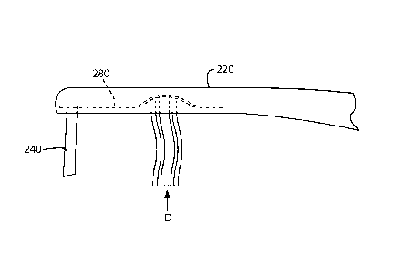
[0030] FIG. 4 is a side view of a brush head according to a third embodiment
of the invention
showing a membrane at the base of a bristle array;
[0031] FIG. 5 is a side view of a modified version of the brush head of FIG. 4
showing the
membrane replaced by a bubble of piezochromic material;
[0032] FIG. 6 is a side view of a fourth embodiment of the invention showing
two handle
sections linked by a pivot.
[0033] FIG. 7 is a cross-sectional view of a fifth embodiment of the invention
showing a
lever mechanism for transmitting brushing force to piezochromic material in
the handle; and
[0034] FIG. 8 is a cross-sectional view of a sixth embodiment of the invention
showing a
hydraulic mechanism for transmitting brushing force to piezochromic material
in the handle.
DETAILED DESCRIPTION OF THE INVENTION
4
CA 02828375 2013-08-27
WO 2012/118487
PCT/US2011/026643
Attorney Docket No: 8953-00-WO-TB
[0035] The following description of the preferred embodiment(s) is merely
exemplary in
nature and is in no way intended to limit the invention, its application, or
uses.
[0036] The invention comprises a toothbrush incorporating an indicator
comprising a
pressure (or force) indicating material which provides a signal without the
provision of a
power supply, such as a battery, and without the provision of electrical
circuitry,
characterized in that the indicator is capable of providing the signal when a
predetermined
brushing pressure (or force) is being or has been applied.
[0037] Thus, the user can be provided with a visible signal that a suitable
brushing force is
being or has been used, and/or a visible signal that an excessive brushing
force is being or has
been used. A suitable brushing force is preferably less than 3.5 N or less
than 3 N or 0.5-2.9
N or 1-2.75 N or 1.5-2.5 N. Thus, in certain embodiments, the brush can be
designed to
generate a visible signal when brushing force is at least 0.5 N, and/or
generate a visible
warning signal when brushing force is 3 N or greater.
[0038] In certain embodiments, the signal is provided when a suitable brushing
force is being
applied and is absent when brushing force is too high.
[0039] Preferably, the pressure signal is a visible signal, which indicates to
the user when a
suitable brushing pressure and/or an unsuitable brushing pressure is being
applied, but then
may relax to its original state, e.g., its original color and/or intensity,
after a period of time.
This may or may not be after the user has finished a normal brushing regime.
As such, the
relaxation time of the material providing the optical response may typically
be in the region
of 1 second to 24 hours, though it is preferably long enough for the user to
register it, and is
preferably less than 24 hours. More preferably, the relaxation time for the
pressure indicating
material is from 1 second to 10 minutes or 1-10 seconds or 2-5 seconds.
[0040] The pressure indicating material according to the invention is a
material adapted to
show an optical response upon the application of pressure. Pressure indicating
materials as
defined herein include piezochromic materials, which as defined herein, refer
to materials
that show a color change in response to pressure (or force) being applied
thereto.
[0041] In certain embodiments, a pressure indicating material is a material
that shows an
optical response to a stimulus other than pressure, wherein the stimulus is
provided to the
material by another element of the toothbrush as a function of brushing force.
[0042] Suitable piezochromic materials include but are not limited to
piezochromic
polymers, such as for example, crystals of toluene sulphonate diacetylene
polymers; or
CA 02828375 2013-08-27
WO 2012/118487
PCT/US2011/026643
Attorney Docket No: 8953-00-WO-TB
copolymers containing poly(diacetylenes) or poly(silylenes). Again, the
pressure indicating
material may be one susceptible to relative changes in refractive index upon
the application
of pressure, for example aromatic solvents containing poly(N-methyl
acrylamide).
[0043] In certain embodiments, the pressure indicating material is
piezochromic material of
the electrocylic ring-opening mechanophore type. Potisek et al., "Mechanophore-
Linked
Addition Polymers." J. Am. Chem. Soc., 2007, 129 (45), pp 13808-13809
discloses suitable
methods for preparing certain electrocylic ring-opening mechanophores of the
present
invention. Preferred mechanophores include spiropyran. Preferred polymers to
which the
mechanophore is linked include poly(methyl acrylate) and poly(methyl
methacrylate).
[0044] In certain embodiments, the indicator is capable of providing a signal
when brushing
pressure is being or has been applied and is absent when brushing pressure is
too high. Thus
it is an essential feature of such embodiments that the pressure indicating
material is so
calibrated to be capable of providing such a signal. An example of such
calibration for a
brush comprising a piezochromic material may be the presence of only a certain
amount of
the active shear sensitive material or the inclusion of an additional
material, such as a
polymer, which may act as a signal modifier, e.g., by changing the viscosity
of the
piezochromic material, which will prevent a signal being provided if the
brushing pressure is
too high.
[0045] It is also envisaged that the signal provided on application of
brushing pressure may
be graduated to reflect changes in brushing pressure within the suitable range
and above the
suitable range. For example, the signal may be green when brushing pressure is
optimal;
amber when pressure is sub-optimal but acceptable and red when pressure is
approaching an
unacceptable level. The signal would, of course, disappear when the correct
pressure is no
longer being applied. In a similar way, the intensity of the optical signal
may vary with the
intensity of the brushing pressure.
[0046] In an alternative aspect of the invention, the pressure indicating
material is activated
not by the process of brushing but by the user's grip. A strong grip may be
suggestive of an
aggressive brushing style which may damage the gums. Thus the indicating
material may be
incorporated so as to provide a signal when the user's grip is within a range
which
corresponds to a correct brushing pressure.
[0047] Indicator materials preferred for use in the invention display an
optical response (a
color change) within the range of pressure generated by brushing, which is not
affected by the
6
CA 02828375 2013-08-27
WO 2012/118487
PCT/US2011/026643
Attorney Docket No: 8953-00-WO-TB
range of temperature to which a brush is normally subjected. A further
property desired of a
preferred indicator material is that this material can relax to its original
state reasonably
quickly. An indicator substance which requires a period of days to recover
would not be
suitable for the present application. It has, however, been found useful to
use a material for
providing the optical response which demonstrates a degree of hysteresis.
[0048] It is envisaged that the relaxation period of the indicator material
may be such that it
can be seen when the correct brushing pressure is being or has been exceeded
during
brushing, i.e., the signal disappears as soon as the correct pressure is no
longer being applied.
[0049] The relaxation period may be so short that changes in brushing
technique are quickly
represented by the indicator material and several changes in brushing
technique may be
made.
[0050] In the known designs, a separate mechanism is used to trigger the
indicator, for
example a predetermined flexure of the brush or movement of the bristles
causes two
components to move relative to each other and to close an electrical circuit.
In a preferred
embodiment of the invention, the need for such a mechanism is avoided, as the
force exerted
on the brush is communicated directly to the indicator.
[0051] Less costly embodiments use a small amount of the pressure indicating
material
located in a pad, plate or bubble located in/on the brush head, in/on the neck
of the brush,
in/on the handle of the brush, and/or in/on the bristles. By way of example,
the optical
indicator (e.g., piezochromic) material can be heat-sealed into a vinyl
envelope, or it can be
otherwise encapsulated. Two plates of the pressure indicating material may be
used, which
plates are squashed together by an applied force. In one example, plates of
the material are
interleaved with the brush bristles. Pressure applied to the bristles causes
bending of the
bristles as well as the plates. In an alternative embodiment, the material is
formed into a
resilient membrane located at the base of the bristles, with the brush head
preferably being
transparent to allow the pressure indicating material to be visually
inspected.
[0052] In another embodiment, a mechanical arrangement is provided to transmit
the force to
the indicator. For example, the brush may have two handle sections linked by a
pivot, a
portion of one of these sections extending beyond the pivot into a cavity
provided in the other
section. Excessive pressure causes the two sections to rotate relative to each
other, in opposite
directions about the pivot, such that one face of the extended portion will be
brought into
contact with the inner surface of the cavity in which it is located. That
interior surface is
7
CA 02828375 2013-08-27
WO 2012/118487
PCT/US2011/026643
Attorney Docket No: 8953-00-WO-TB
provided with a pad of the pressure indicating material. Designs such as this,
which employ
moving elements to transmit the applied force to the indicator, have the
advantage that the
force may be amplified or reduced to fall within the response range of the
pressure indicating
material.
[0053] With regard to the other parts of the brush, the brush body may be made
of materials
and with methods used in the art, for example using injection molding
techniques and
materials such as polypropylene and polymethyl methacrylate. The bristles may
be made of
materials which are used in the art, including nylon and
polybutylterephthalate.
[0054] Referring to the drawings, FIG. 1 shows a toothbrush 10 having a head
20 integrally
formed with a handle 30 via a neck 60. The head 20 is provided with bristles=
40 made of
nylon. The head 20 and handle 30 are made of a resilient transparent material
such as
polymethyl methacrylate and define a cavity 50 extending substantially along
the entire
length of the brush 10. The cavity 50 is filled with a piezochromic material.
A predetermined
pressure (suitable for brushing teeth) applied to the bristles 40, or a
predetermined flexure of
the handle 30, will be transmitted to, and thereby cause an optical response
(such as a change
of color) of, the piezochromic material. The cavity 50 may, instead of
extending substantially
the entire length of the brush 10, be more localized, for example, it may be
confined to a neck
region 60 joining the handle 30 to the head 20.
[0055] FIGS. 2 and 3 show respectively a side and plan view of the head 120 of
a second
embodiment of the invention to a larger scale. Bristles 140 are interleaved
with plates 170
made of piezochromic material. Force applied to the brush head 120 in the
direction of
arrow F causes flexure of the bristles 140 and the plates 170 in the way
shown, and this
deformation is transmitted to the plates 170 which will cause an optical
response such as a
change in color in the piezochromic material as a function of brushing
pressure.
[0056] FIG. 4 shows a side view of a third embodiment of the invention, and
shows a brush
head 220 provided with bristles 240. The base of each bristle 240 is attached
to a flexible
membrane 280, which contains the piezochromic material. Force applied to the
bristles 240 in
the direction of arrow D is transmitted to the membrane 280, and causes it to
deform.
Deformation of the membrane 280 stresses the piezochromic material contained
within it,
causing an optical response in the material such as a change of color on the
application of
suitable force.
8
CA 02828375 2013-08-27
WO 2012/118487
PCT/US2011/026643
Attorney Docket No: 8953-00-WO-TB
=
[0057] FIG. 5 shows a modified version of the brush head of FIG. 4, in which
piezochromic
material is contained in a sac 290. Force applied to the bristles 240 is
transmitted to the sac
290 via flexible membrane 280 causing it to deform, thereby causing an optical
response in
the piezochromic material. In this modified brush head, the membrane 280 does
not contain
piezochromic material. Indeed, in a further modification, the membrane is not
required, in
which case force applied to the bristles 240 is transmitted directly to the
sac 290.
[0058] FIG. 6 shows a side view of a fourth embodiment of the invention, in
which a handle
330 and a neck 360 of the brush 310 are pivotally connected at 400. A portion
410 (indicated
in dotted lines) of the neck 360 extends beyond the pivot 400 into a cavity
350 formed in the
handle 330. The neck 360 is integral with the head 320 of the brush 310.
[0059] In this embodiment, at least the handle 330 is formed of a transparent
plastics material
such as polymethyl methacrylate. Force applied to the bristles 340 of the
brush 310 in the
direction of arrow G, whilst the handle 330 is being held firmly, causes the
handle and the
head 320 to rotate relative to each other about the pivot 400 in the
directions of the arrows HI
and H2.
[0060] Rotation is impeded as the neck portion 410 comes into contact with a
pad 420
containing a piezochromic material. Continued mechanical applied to the head
320 of the
brush 310 is transmitted to the pad 420 causing an optical response in the
piezochromic
material.
[0061] FIG. 7 shows a cross-sectional view of a fifth embodiment of the
invention, in which
brush 710 contains lever 700, which pivots about fulcrum 780 when force J is
applied against
bristles 740, such that force J is transmitted from bristles 740 to
piezochromic material 790,
which is located in the neck of the brush. The optical response of
piezochromic material 790
is visible through window 770. Although FIG. 7 shows the window in the front
side (i.e.,
bristle side) of brush 710, it is also within the scope of the invention for
piezochromic
material 790 and window 770 to be placed on the back side of the brush with
lever
mechanism rearranged, e.g., to a second class type lever wherein fulcrum 780
is located
further down the neck or handle than piezoelectric material 790.
[0062] FIG. 8 shows a cross-sectional view of a sixth embodiment of the
invention, in which
brush 810 contains bladder 880, which hydraulically transmits force K, which
is applied
against bristles 840, to piezochromic material 890 located in the neck of the
brush. The
optical response of piezochromic material 890 is visible through window 870.
Although
9
=
CA 02828375 2015-01-21
62301-3347
FIG. 8 shows the window in the front side of brush 810, it is also within the
scope of the
invention for piezochromic material 890 and window 870 to be placed on the
back side of the
brush.
[0063] In alternative embodiments, polarized materials are used as pressure
indicating
material, with pieces of polarized material being configured such that their
planes of
polarization are at 90 to each other. One of the pieces of material is fixed,
and the other is
able to move on the application of excessive pressure (for example by being
attached to a
mechanical type embodiment as described in conjunction with FIGS. 6 and 7
above) such
that a different orientation of polarization planes is achieved, and thereby a
color change is
observed. Otherwise, also envisaged is an embodiment of sheet form polarizers
which are
orientated parallel to each other, and which are separated by an arrangement
such as a coiled
spring and/or a helical arrangement, whereby the two polarizers are caused to
rotate relative
to each other when they are brought closer to or further apart from each other
in response to
changes in brushing pressure. As a result, the polarizers adopt a different
configuration
relative to each other, and a color change is observed.
100641 In firther alternative embodiments, the pressure indicating material is
a polymer that
signals brushing force by re-orientation of initial dye-dye interactions
within neighboring
polymer fibers. Such pressure-sensitive polymers can be created by taking
advantage of the
property of certain dye molecules that change color based on their proximity
to other dye
molecules. These "proximity dye based polymers" can be used, e.g., in
embodiments
analogous to those of FIG. 6, wherein the relative rotation of handle 330 and
head 320 about
pivot 400 will cause the dye molecules inside the polymer to approach each
other, and in
embodiments analogous to that of FIGS. 2-3, wherein brushing force causes
proximity dye
based polymers of the bristles to approach each other. The enhanced proximity
causes the
emission properties of the dye molecule to change either via charge transfer
interaction or
excimer formation. This appears as an optically different color. Repeated high
pressure
brushing may prevent reversibility and lock in color and could also be used as
an indicator for
the lifetime of a toothbrush.
[0065] As used throughout, ranges are used as shorthand for describing each
and every value
that is within the range. Any value within the range can be selected as the
terminus of the
range.
CA 02828375 2015-01-21
62301-3347
In the event of a conflict in a definition in the present disclosure and that
of a cited reference,
the present disclosure controls.
11