Note: Descriptions are shown in the official language in which they were submitted.
CA 02828875 2013-08-30
1
DESCRIPTION
TITLE OF THE INVENTION: REBOILER
TECHNICAL FIELD
[0001]
The present invention relates to a large-sized reboiler (heat exchanger).
BACKGROUND ART
[0002]
In recent years, the greenhouse effect caused by carbon dioxide has been
pointed
out as one cause for global warming phenomena, and there is a tendency that
the demand
of restraining the emission of carbon dioxide becomes more intense to protect
the global
environment. For a power generating facility such as a thermal power plant
using a large
amount of fossil fuel, there has been proposed a method in which carbon
dioxide in
combustion flue gas is removed and recovered by bringing the combustion flue
gas of a
boiler into contact with an amine-based carbon dioxide absorbing solution
(Patent
Document 1).
As a method for removing and recovering carbon dioxide from the combustion
flue gas by using a carbon dioxide-absorbing solution, there has been employed
a carbon
dioxide recovery system in which the combustion flue gas is brought into
contact with a
carbon dioxide-absorbing solution in an absorption tower, and the absorbing
solution
having absorbed carbon dioxide is heated in a regeneration tower to liberate
the carbon
dioxide and to regenerate the absorbing solution, which is circulated again to
the
absorption tower for reuse. According to the carbon dioxide recovery system,
carbon
dioxide existing in a gas is absorbed by the absorbing solution in the
absorption tower,
subsequently the carbon dioxide is separated from the absorbing solution by
heating the
absorbing solution in the regeneration tower, the separated carbon dioxide is
recovered
separately, and the regenerated absorbing solution is circulatingly used again
in the
absorption tower. A reboiler is used to separate and recover the carbon
dioxide by
CA 02828875 2015-10-02
95839-1
2
heating the absorbing solution in the regeneration tower.
Also, the reboiler is used for heat exchange between a liquid refrigerant and
cold water,
and as a result, the refrigerant is vaporized, while the cooled cold water is
circulated in a
building for air cooling (Patent Document 2).
PRIOR ART DOCUMENTS
Patent Documents
[0003]
Patent Document 1: JP 2011-020090A
Patent Document 2: JP 2002-349999A
SUMMARY OF INVENTION
Technical Problem
[0004]
The present inventors have aimed at saving space and reducing plant cost by
combining
a plurality of small-sized reboilers into one large-sized apparatus. However,
they have found
that in a reboiler which allows a liquid to be supplied from a lower part
thereof, and the
vaporized gas to be discharged from an upper part thereof, the gravity of the
vaporized gas
cannot be ignored so that the gas stays near an upper portion in a vessel and
serves as a gas-
form lid, thereby hindering the recovery of gas. The present invention
provides a large-sized
reboiler that prevents the vaporized gas from staying, and can achieve space
saving and
reduction in plant cost.
Solution to Problem
[0005]
The present invention provides a large-sized reboiler comprising: a vessel of
which a
liquid is supplied from a lower part and a vaporized gas is discharged from an
upper part; and a
heat transfer tube group forming a void penetrating in an up-and-down
direction in the vessel,
wherein a maximum length of a cross-sectional area of a flow path for the
liquid exceeds 2m,
and the void occupies 5 to 10% of the cross-sectional area of the flow path,
and wherein the
CA 02828875 2015-10-02
95839-1
3
void exists between the periphery of an inner wall in the up-and-down
direction of the vessel
and the heat transfer tube group so as to be ring-shaped.
Effect of Invention
[0006]
According to the present invention, although the size of a reboiler is made
larger, a
vaporized gas can be prevented from staying, and space saving and reduction in
plant cost can
be achieved.
BRIEF DESCRIPTION OF DRAWINGS
[0007]
Figure 1 is a schematic view showing a large-sized reboiler for recovering a
gas (for
example, carbon dioxide) from a liquid (for example, a carbon dioxide-
containing absorbing
solution).
Figure 2 is a sectional view taken along the line A-A of Figure 1, showing an
embodiment in which the heat transfer tube group is arranged in the same
manner as that in a
small-sized reboiler.
Figure 3 is a sectional view taken along the line A-A of Figure 1, showing an
embodiment in which the heat transfer tube group is arranged in such a manner
that a void is
formed between the periphery of an inner wall in the up-and-down direction of
a reboiler
vessel and the heat transfer tube group.
Figure 4 is a sectional view taken along the line A-A of Figure 1, showing one
embodiment in which voids penetrating in the up-and-down direction are formed
within the
heat transfer tube group.
Figure 5 is a sectional view taken along the line A-A of Figure 1, wherein
Figure 5(b)
shows an arrangement in which a void is formed between the periphery of an
inner wall in the
up-and-down direction of the reboiler vessel and the heat transfer tube group,
while Figure
5(a) shows a blackened or black-colored region in which the vapor quality of
the heat transfer
tube group in said arrangement is 0.1 or less.
Figure 6 is a sectional view taken along the line A-A of Figure 1, wherein
Figure 6(b)
shows an arrangement in which voids penetrating in the up-and-down direction
are
CA 02828875 2013-08-30
=
4
formed within the heat transfer tube group, while Figure 6(a) shows a
blackened or
black-colored region in which the vapor quality of the heat transfer tube
group in said
arrangement is 0.1 or less.
Figure 7 is a sectional view taken along the line A-A of Figure 1, wherein
Figure
7(b) shows an arrangement of the heat transfer tube group in the same manner
as that in a
small-sized reboiler, while Figure 7(a) shows a blackened or black-colored
region in
which the vapor quality of the heat transfer tube group in said arrangement is
0.1 or less.
DESCRIPTION OF EMBODIMENTS
[0008]
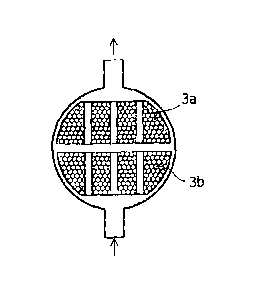
Figure 1 shows a large-sized reboiler 1 for recovering a gas (for example,
carbon
dioxide) from a liquid (for example, a carbon dioxide-containing absorbing
solution).
The reboiler 1 comprises a heat transfer tube group 3 in a cylindrical vessel
2 into which a
liquid is supplied through lower inlets 6. The heat transfer tube group 3
comprises a
bundle of a large number of heat transfer tubes through which a heating fluid
H is allowed
to flow, and lies in the longitudinal direction of the vessel 2. The heat
transfer tube
group 3 is divided into an advance-side heat transfer tube group 3a, which
communicates
with a heating fluid inlet 4, and a return-side heat transfer tube group 3b,
which
communicates with a heating fluid outlet 5. The heating fluid H flowing into
the vessel 2
through the heating fluid inlet 4 goes in the vessel 2, turns back across the
inside of the
vessel 2, goes again in the vessel 2, and flows to the outside through the
heating fluid
outlet 5. In this process, the heating fluid H is heat-exchanged with a liquid
introduced
into the vessel 2 and cooled, while the liquid is heated by the heating fluid
H and
discharged through upper outlets 7 of the vessel as a mixture of gas (for
example, carbon
dioxide gas) and treated liquid (for example, an amine solution).
[0009]
Figure 2 is a sectional view taken along the line A-A of Figure 1, and shows
an
embodiment in which the heat transfer tube group is arranged in the same
manner as that
in a small-sized reboiler. In this large-sized reboiler of which a liquid is
supplied from a
lower part and a vaporized gas is discharged from an upper part, since an
amount of the
CA 02828875 2013-08-30
= 5
liquid to be treated is large, the vaporized gas stays near the upper portion
in the vessel
owing to the gravity of the vaporized gas, thereby forming a region R of
staying vapor.
The staying vapor serves as a lid so that the liquid circulates under the
staying vapor
(indicated by arrows in Figure 2), lowering the vapor recovery efficiency.
[0010]
Figure 3 is a sectional view taken along the line A-A of Figure 1, showing an
embodiment in which the heat transfer tube group is arranged in such a manner
that a void
penetrating in the up-and-down direction of the reboiler vessel is formed.
Figure 3
shows an embodiment in which the heat transfer tube group is arranged in such
a manner
that a void is formed between the periphery of an inner wall in the up-and-
down direction
of the reboiler vessel and the heat transfer tube group. In the other words,
this
embodiment is one in which a downcomer, which is a ring-shaped void, is
provided
between the heat transfer tube group and a shell, whereby the vapor and the
liquid are
separated from each other, and also the flow rate of the liquid is increased.
The increase
in the flow rate of the liquid circulating in the heat transfer tube group
allows the area in
which the liquid is in contact with the heat transfer tube group to increase,
so that the
heat-exchanging performance is enhanced. Also, since the stay of vapor can be
avoided,
the liquid is easy to flow, and the heat exchange of the liquid with the
heating fluid is
promoted, so that the improvement in heat transfer rate can be achieved. The
deviation
of boiling in the longitudinal direction perpendicular to the up-and-down
direction is
eliminated, and thereby the average heat transfer performance of a vaporizer
can be
improved. The heat transfer rate between each heat transfer tube and air
bubbles is lower
than the heat transfer rate between each heat transfer tube and the liquid.
However, since
the formation of the air bubbles is suppressed, the decrease in the heat
transfer rate is
restrained.
[0011]
Figure 4 is a sectional view taken along the line A-A of Figure 1, showing an
embodiment in which the heat transfer tube group is arranged in such a manner
that a void
penetrating in the up-and-down direction of the reboiler vessel is formed.
Figure 4
shows an embodiment in which voids penetrating in the up-and-down direction
are
CA 02828875 2013-08-30
6
formed within the heat transfer tube group. In other words, columnar voids are
provided
within the heat transfer tube group, so that the vapor does not stay within
the heat transfer
tube group, and easily comes out upward. Easy separation of the vapor from the
liquid
facilitates the liquid to easily come into contact with the heat transfer tube
group, so that
the heat-exchanging performance is enhanced. The liquid can be supplied
sufficiently to
the upper heat transfer tubes in the heat transfer tube group. Therefore, the
heat transfer
performance of the upper heat transfer tubes is improved, so that the boiling
performance
is improved. The heat transfer rate between each heat transfer tube and air
bubbles is
lower than the heat transfer rate between each heat transfer tube and the
liquid. However,
since the formation of the air bubbles is suppressed, the decrease in the heat
transfer rate is
restrained.
[0012]
Although not shown in figures, an embodiment in which those in Figures 3 and 4
are combined can also be used. There may be used an embodiment in which the
voids
are formed in the vessel of which the liquid is supplied from the lower part
and the
vaporized gas is discharged from the upper part, and penetrate in the up-and-
down
direction between the periphery of the inner wall in the up-and-down direction
of the
vessel and the heat transfer tube group, as well as within the heat transfer
tube group.
[0013]
In the large-sized reboiler described in this specification, the maximum
length of
the cross-sectional area of a flow path for the liquid, that is, the maximum
length of the
cross-sectional area in the longitudinal direction usually perpendicular to
the up-and-down
direction is larger than 2m, preferably 3m or larger, and further preferably
4m or larger.
The upper limit of the maximum longitudinal length of the cross-sectional area
is not
subject to any special restriction, and is determined in consideration of the
quantity of
liquid treated by the reboiler and the content and efficiency of the
subsequent treatment of
the recovered gas and the liquid from which the gas has been removed. Also,
when the
length or the shell diameter is large, an embodiment in which a vertical-type
reboiler is
used is also available, and therefore the upper limit of the maximum
longitudinal length is
not restricted especially.
CA 02828875 2013-08-30
= 7
The maximum length of the cross-sectional figure of the flow path in the
longitudinal direction is, for example, a diameter when the cross-sectional
figure of the
flow path is a circle, a major axis when it is an ellipse, and the longest
diagonal line when
it is a polygon such as a triangle, a quadrangle or an octagon.
[0014]
In the area of the cross-sectional figure of the flow path in the vessel of
which the
liquid is supplied from the lower part and the vaporized gas is discharged
from the upper
part, that is, in the area of the cross-sectional figure of the flow path in
the longitudinal
direction usually perpendicular to the up-and-down direction, the void
penetrating in the
up-and-down direction preferably occupies an area of 5 to 10%, while the heat
transfer
tube group preferably occupies a space of 90 to 95% by ignoring the
longitudinal space
between the tube group on the return side and the tube group on the advance
side.
Therefore, as described relating to Figures 3 and 4, the vapor does not stay
in the upper
portion of the heat transfer tube group, and easily comes out upward. Easy
separation of
the vapor from the liquid facilitates the liquid to easily come into contact
with the heat
transfer tube group, so that the heat-exchanging performance can be enhanced.
When
the void area is less than 5% of the cross-sectional area of the flow path,
the vapor stays.
When the void area is more than 10%, the heat transfer efficiency decreases.
[0015]
The liquid to be treated by the reboiler is not particularly limited as long
as it
generates a gas by heating, and includes an amine solution having absorbed
carbon
dioxide and a liquid-form refrigerant. The amine solution having absorbed
carbon
dioxide is heated by the reboiler so that the amine solution is regenerated
with generation
of carbon dioxide. A liquid refrigerant is also treated by the reboiler, and
heat exchange
is carried out between the liquid refrigerant in the reboiler vessel and water
caused to flow
in the heat transfer tubes, thereby vaporing the liquid refrigerant and
circulating the cooled
water through tubes laid in a structure, whereby cooling is performed through
heat
exchange with air in each space.
[0016]
When the circulation ratio of the liquid to be treated by the reboiler is less
than 3,
CA 02828875 2013-08-30
8
the generation of gas may become unstable. The circulation ratio is preferably
10 or
more. The circulation ratio is expressed by the equation: (Gf + Gg)/Gf wherein
Gf is the
flow rate (weight) of the circulating liquid, and Gg is the flow rate (weight)
of the
generating gas.
The throughput of the liquid in the reboiler is determined by considering the
quality and/or capacity of treatment in the succeeding process.
EXAMPLE
[0017]
Examples 1 and 2, and Comparative Example 1
Figures 5 to 7 show analysis data of changing the arrangement of the heat
transfer tube group in the large-sized reboiler shown in Figure 1, in which
the
cross-sectional area of the flow path for the liquid is a rectangle of 2m x
3m, and the
diagonal line of the rectangle, which is the maximum length, is 3.6m, and the
liquid
having a temperature of 118 C is heated to 123 C through heat exchange at a
liquid flow
rate of 50 kg/m2s (at the outlet of heat transfer tube group). Figures 5 to 7
correspond to
the sectional view taken along the line A-A of Figure 1. In Figures 5(a) to
7(a), a region
in which the vapor quality is 0.1 or less, is blackened or shown in black
color. The vapor
quality is the weight ratio of the vapor to the mixture of the liquid and the
vapor from the
liquid. In Figures 5(b) to 7(b), the arrangement of the heat transfer tube
group is shown
in a half of the A-A section of Figure 1.
[0018]
Example 1 shown in Figure 5 is an embodiment in which the heat transfer tube
group is arranged in such a manner that a void is formed between the periphery
of the
inner wall in the up-and-down direction of the reboiler vessel and the heat
transfer tube
group. As shown in Figure 5(a), this embodiment has the vapor quality of 0.1
or less
excluding only a part, and a high heat transfer efficiency. A region in which
the vapor
quality x is high (x exceeds 0.1 at the atmospheric pressure) is reduced,
which lowers the
possibility that the heat transfer tubes are dried out.
Example 2 shown in Figure 6 is an embodiment in which voids penetrating in the
CA 02828875 2013-08-30
. = 9
up-and-down direction are formed within the heat transfer tube group. As shown
in
Figure 6(a), although the existing ratio of a region in which the vapor
quality exceeds 0.1
increases in the upper portion of vessel, an allowable heat transfer
efficiency is obtained.
Comparative Example 1 shown in Figure 7 is an embodiment in which the heat
transfer tube group is arranged in the same manner as that in a small-sized
reboiler. As
shown in Figure 7(a), the existing ratio of a region in which the vapor
quality exceeds 0.1
is high in the upper portion of vessel, and a poor heat transfer efficiency is
obtained.
EXPLANATION OF SYMBOLS
[0019]
1: large-sized reboiler
2: vessel
3: heat transfer tube group
3a: advance-side heat transfer tube group
3b: return-side heat transfer tube group
4: heating fluid inlet
5: heating fluid outlet
6: lower inlet
7: upper outlet
H: heating fluid
R: region of staying vapor