Note: Descriptions are shown in the official language in which they were submitted.
CA 02829098 2013-10-01
WO 2012/109058 PCT/US2012/023339
DIAPERING RESTRAINT
BACKGROUND OF THE INVENTION
Field of the Invention
The present invention relates generally to a personal restraint device. More
particularly,
the present invention relates to a personal restraint device for use on a
child during the process of
changing the child's diaper.
Description of the Related Art
A number of diapering restraints have been previously described. The majority
of such
0 previously described restraints generally fall into two categories -
those utilizing a single torso
strap and those utilizing multiple, elongated straps to achieve a four-point
restraint system. A
=
single strap device, while sometimes capable of reducing the risk of fall from
the changing
surface, often fails to prevent rolling within the loop created by the strap.
These single strap
devices also allow the child to sit up if the strap is placed, or the child
moves to such a position
5 that places the strap, near or below the waist of the child. While a four-
point restraint system is
much more effective at limiting a child's movement, these systems often
present an inherently
dangerous situation as the multiple, narrow, elongated straps provide an
opportunity for a child
to become entrapped or strangled. In addition to the hazard posed by devices
that utilize straps,
the straps make for a complicated process of applying the device to the
infant. Most restraints
0 include four separate straps that must be combined in a specific
configuration, often requiring the
various straps to be applied in a specific sequence in order to effectively
restrain the child. This
is inefficient and often confusing for a caregiver who is already struggling
with an active and/or
resistant child.
5 SUMMARY OF THE INVENTION
The present invention is a restraint device used for the purpose of
restricting the
movement of a child during the diaper changing process. Embodiments of the
present invention
utilize two vest-like flaps that are affixed to the diaper changing surface
and secured to one
another via a hook-and-loop attachment.
0 An object of the present invention is to provide a diapering
restraint device that is easy
and safe to use.
1
CA 02829098 2013-10-01
WO 2012/109058 PCT/US2012/023339
Additional features and advantages of the invention will be set forth in the
descriptions
that follow and in part will be apparent from the description, or may be
learned by practice of the
invention. The objectives and other advantages of the invention will be
realized and attained by
the structure particularly pointed out in the written description and claims
thereof as well as the
appended drawings.
To achieve these and other advantages and in accordance with the purpose of
the present
invention, as embodied and broadly described, the present invention provides a
child restraint
device for use with a changing surface for diapering a child, which includes:
a rear panel; a first
vest flap and a second vest flap each attached to the rear panel; wherein the
first vest flap has a
0 multiple-sided shape with a first side attached to a top edge of the rear
panel, a third side
attached to a first side edge of the rear panel, and a second side between the
first and third side
forming an arm opening, wherein the second vest flap has a multiple-sided
shape with a first side
attached to the top edge of the rear panel, a third side attached to a second
side edge of the rear
panel, and a second side between the first and third side forming an arm
opening, wherein the
5 attachment location of the first vest flap to the top edge of the rear
panel and the attachment
location of the second vest flap to the top edge of the rear panel are spaced
apart from each other
for accommodating a head of the child, and wherein the first and second vest
flaps include means
for attaching the first and second vest flaps together; and means for securing
the rear panel to the
changing surface.
0 In another aspect, the present invention provides a child restraint
device for diapering a
child, which includes: a changing surface; a first vest flap and a second vest
flap each attached to
the changing surface; wherein the first vest flap has a multiple-sided shape
with a first side
attached to the changing surface along a transverse line of the changing
surface, a third side
attached to the changing surface along a first longitudinal line of the
changing surface, and a
5 second side between the first and third side forming an arm opening,
wherein the second vest
flap has a multiple-sided shape with a first side attached to the changing
surface along the
transverse line of the changing surface, a third side attached to the changing
surface along a
second longitudinal line of the changing surface, and a second side between
the first and third
side forming an arm opening, wherein the attachment locations of the first and
second vest flaps
0 along the transverse line of the changing surface are spaced apart from
each other for
2
CA 02829098 2015-01-13
accommodating a head of the child, and wherein the first and second vest flaps
include means for attaching the first and second vest flaps together.
It is to be understood that both the foregoing general description and the
following detailed description are exemplary and explanatory and are intended
to
provide further explanation of the invention as claimed.
In one aspect of the invention, there is provided a child restraint device for
use with a changing surface for diapering a child, comprising: a rear panel; a
first
vest flap and a second vest flap each attached to the rear panel; wherein the
first
vest flap has a multiple-sided shape with a first side attached to a top edge
of the
0 rear panel, a third side attached to a first side edge of the rear panel,
and a second
side between the first and third side funning an arm opening, wherein the
second
vest flap has a multiple-sided shape with a first side attached to the top
edge of the
rear panel, a third side attached to a second side edge of the rear panel, and
a
second side between the first and third side forming an arm opening, wherein
the
5 attachment location of the first vest flap is along the top edge of the
rear panel and
the attachment location of the second vest flap is along the top edge of the
rear
panel are spaced apart from each other for accommodating a head of the child,
and wherein the first and second vest flaps include means for attaching the
first
and second vest flaps together; and means for securing the rear panel
comprising
0 a first affixing flap and a second affixing flap attached along the first
side edge
and along the second side edge of the rear panel, respectively, wherein the
first
and second affixing flaps include means for attaching the first and second
affixing
flaps together when the rear panel and the second affixing flaps are wrapped
around the changing surface.
5 In another aspect of the invention, there is provided a child
restraint device
for diapering a child, comprising: a changing surface; a first vest flap and a
second vest flap each attached to the changing surface; wherein the first vest
flap
has a multiple-sided shape with a first side attached along the changing
surface
along a transverse line of the changing surface, a third side attached to the
0 changing surface along a first longitudinal line of the changing surface,
and a
second side between the first and third side forming an arm opening, wherein
the
2a
CA 02829098 2015-01-13
second vest flap has a multiple-sided shape with a first side attached to the
changing surface along the transverse line of the changing surface, a third
side
attached to the changing surface along a second longitudinal line of the
changing
surface, and a second side between the first and third side forming an arm
opening, wherein the attachment locations of the first and second vest flaps
along
the transverse line of the changing surface are spaced apart from each other
for
accommodating a head of the child, and wherein the first and second vest flaps
include means for attaching the first and second vest flaps together and means
for
securing the child restraint device comprising a first affixing flap and a
second
0 affixing flap attached along the first side edge and along the second
side edge on
the changing surface, respectively.
2b
CA 02829098 2015-01-13
=
WO 2012/109058 PCPUS21112/023339
BRIEF DESCRIPTION OF THE DRAWINGS
FIG, I is a too elan view of a restraint device according to a Preferred
embodiment of the
present invention.
0 FIG. 2 is an isometric view of the embodiment of FIG, 1 being fastened
on the underside
of a changing pad.
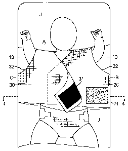
FIG. 3 is a top plan view of the embodiment of FIG. 1, shown mounted on a
changing
pad and holding a child.
FIG. 4 is a cross-sectional view of the embodiment of FIG. 1 taken along line
4-4 of
FIG. 3.
DETAILED DESCRIPTION OF THE PREFERRED EMBODIMENTS
keferring now to embodiments of the invention in more detail, in HU, 1 there
is shown a
restraint device (I) in a preferred embodiment having a rear panel (10), a
first vest flap (.20), a
.0 second vest flap (30). a first affixing flap (40) and a second affixing
flap (50). The device (1) is
made of fabric materials (including mesh), and may be made by stitching
multiple pieces of
fabric materials (same 01 different types of fabric) together.
A first arm opening (22) is created by the attachment of the first vest flap
(20) at the top
edge (A) of rear panel (10) and a first side edge (B) of rear panel (10). A
second arm opening
.5 (32) is similarly created by the attachment of second vest flap (30) to
top edge (A) and a second.
side edge (C) of rear panel (10) which is opposite the first side edge (B).
The attachment
locations of the first vest flap (20) on the top edge (A) and on the side edge
(B) are on one side of
a longitudinal centerline of the rear panel (10); the attachment locations of
the second vest flap
(30) on the top edge (A) and the side edge (C) are on the other side of the
longitudinal centerline
-0 (the longitudinal direction is the up-down direction in FIG. I), The two
attachment locations of
3
CA 02829098 2013-10-01
=
WO 2012/109058 PCT/1JS2012/023339
the first and second vest flaps (20, 30) to the top edge (A) are spaced apart
from each other to
accommodate the head of the child.
Generally speaking, as shown in FIG. 1, each vest flap (20 or 30) has a six-
sided shape.
The first side (20a, 30a) is attached to the top edge (A) of the rear panel
(10); the third side (20c,
30c) is attached to the side edge (B or C) of the rear panel (10); the second
side (20b, 30b) is
located between the first and third side to form the arm opening; the fourth
side (20d, 30d) is
aligned with the bottom edge of the rear panel (10); the sixth side (20f, 30f)
runs from the top
edge (A) down in a generally diagonal direction crossing the longitudinal
center line of the rear
panel (10); and the fifth side (20e, 30e) is located between the fourth side
and the sixth side.
0 Preferably, the first, third and fourth sides are straight, while the
second side is curved to form a
suitable arm opening. The shapes of the fifth and sixth sides are not
important; in fact, these two
sides may be shaped in a smooth curve.
In the embodiment shown in FIG. 1, the rear panel (10) is generally
rectangular shaped.
Alternatively, the rear panel (10) may have different shapes. For example, it
may have the two
5 upper corners cut in a shape corresponding to the shape of the arm
openings of the first and
second vest flaps (20, 30).
FIG. 1 depicts the preferred embodiment of the invention with the vest flaps
(20, 30) in a
closed configuration having the first vest flap (20) secured to the second
vest flap (30) via
complementary hook and loop surfaces (21, 31), with one such surface (21)
located on the front
0 of the first vest flap (20), and the other such surface (31) located on
the back of the second vest
flap (30) (see also FIGS. 3 and 4).
As shown in FIG. 1, the first and second affixing flaps (40, 50) are attached
to the rear
panel (10) along the side edges (C and B), respectively. As shown in FIG. 2,
and also
demonstrated in FIG. 4, the device can be fastened around a stable changing
surface (J), such as
5 a standard, contoured changing pad, via complementary hook and loop
surfaces (41, 51) located
at the ends of the first and second affixing flaps (40, 50).
In the illustrated embodiment (FIG. 1), the affixing flaps (40, 50) are
generally
rectangular in shape and are attached to the rear panel (10) along the entire
lengths of the edges
(C, B). In an alternative embodiment (not shown), the affixing flaps (40, 50)
may have a tapered
0 shape so the free ends near the hook and loop surfaces (41, 51) are
shorter than the ends that are
attached to the rear panel (10). In another embodiment, the affixing flaps
(40, 50) are attached to
4
CA 02829098 2013-10-01
WO 2012/109058 PCT/US2012/023339
the side edges (C, B) along part of their lengths. In another embodiment (not
shown), each
affixing flap may include multiple affixing bands attached to the rear panel
(10) along an edge (C
or B) at multiple locations.
In the illustrated embodiment (FIG. 2), the ends of the first and second
affixing flaps (40,
50) are attached to each other by the hook and loop surfaces (41, 51) whereby
the restraint device
(1) is wrapped around and secured to the changing pad (J). In an alternative
embodiment (not
shown), each end of the first and second affixing flaps (40, 50) is attached
directly to the back
side of the changing pad (J) by hook and loop surfaces.
In another alternative embodiment (not shown), the device (1) may be
constructed with a
0 continuous affixing loop having the circumference approximately equal to
that of the changing
pad (J). This may be thought of as having the two affixing flaps (40, 50)
permanently jointed to
each other. The changing pad (J) can then pass through the affixing loop and
the restraint can be
positioned appropriately to receive a child.
In yet another alternative embodiment, the affixing flaps (40, 50) are
eliminated; rather,
5 other means of securing the rear panel (10) to the changing pad (J) are
provided, such as hook
and loop surfaces located on the back of the rear panel (10) and the front
side of the changing
pad (J) to directly attach the rear panel to the front side of the changing
pad (J).
In addition to the various means described above, other suitable means may be
used to
secure the rear panel (10) to the changing surface. Several types of changing
surfaces are
0 commonly used standard-size, contoured changing pads; plastic, wall-
mounted changing
boards (as commonly found in public restrooms); oversized dresser top pads;
etc.¨and different
affixing means may be suitable for different kinds of surfaces. For example,
if a standard width,
contoured changing pad is being used, some form of affixing flaps will easily
secure the restraint
to the changing pad; however, if the changing surface is very large, such as
an oversized pad
5 used on a dresser top, it may be preferable to directly attach the rear
panel (10) to the changing
surface as a very large changing surface would require excessively long
affixing flaps. The
embodiment shown in FIGS. 1, 2 and 4 is preferred because it accommodates the
most
commonly used changing pads and is flexible and easy to use.
In yet another alternative embodiment, the rear panel (10) is eliminated, and
the vest flaps
0 (20, 30) are directly attached to the changing surface at the locations
that they would have been
attached to the rear panel (10), forming the arm openings and the space for
accommodating the
5
CA 02829098 2015-01-13
WO 2012/109058 PCUUS2012/023339
head. In other words, the first sides (20a, 30a) of the first and second vest
flaps are attached to
the changing surface along a transverse line where the top edge of the rear
panel (10) would have
been, the third sides (20c, 30c) of the of the first and second vest flaps are
attached to the
changing surface along two transverse lines where the two side edges of the
rear panel would
have been, and the. fourth sides (20d, 30d) of the first and second vest flaps
are aliened along a
transverse line where the bottom edge of the rear panel (10) would have been.
In the descriptions above, complementary hook and loop surfaces are used at
various
places to attach two members to each other. As alternatives to hook and loop
surfaces, other
attaching means may be used to .attach the two members to each other, such as
snaps, buttons,
0 zippers, strings, buckles, etc. hook and loop surfaces are preferred
because they are flat and
easy to use.
Referring now to FIG. 3, the restraint device (1) is shown in use, secured to
a changing
pad (J) and holding a child. To position the child in the restraint, the first
and second vest flaps
(20, 30) are opened to reveal the rear panel (10). The child is then placed
onto rear panel ( 10) in
5 a supine position with shoulders approximately even with the top edge (A)
of the restraint. The
child's arms are then inserted into the first and second arm openings (22,
32). The first vest flap
(20) is then laid across the child's torso. The second vest flap (30) is then
similarly laid across
the child's torso and over the first vest flap (20) such that hook and loop
surface (31) of the
second vest flap (30) overlaps with complimentary hook and loop surface (21)
of first vest flap
.0 (20) to maintain the device in a closed position. Once closed, the
device holds the child in a
position that prevents him from rolling, sitting up or sliding on the changing
pad. The child is
also positioned such that there is unimpeded access to the diaper area and the
child's legs are free
to he lifted as needed to facilitate diaper teinuval, cleaning, application of
oinonen(s ui thin
diaper area treatments and for positioning and securing of a clean diaper.
.5 FIG. 4 provides a cross-sectional view of the device (1) shown wrapped
around a
changing pad (õI) and holding the torso of a child (K). This figure
illustrates the relative positions
of the two vest flaps (20, 30), the rear panel (10) and the two affixing flaps
(40, 50). Also
illustrated in this figure is the overlapping nature of the hook and loop
surfaces (21, 31) and (41,
51) which serve to fasten the vest flaps (20, 30) and affixing flaps (40, 50),
respectively.
6