Language selection

Search

Patent 2829173 Summary

Third-party information liability

Some of the information on this Web page has been provided by external sources. The Government of Canada is not responsible for the accuracy, reliability or currency of the information supplied by external sources. Users wishing to rely upon this information should consult directly with the source of the information. Content provided by external sources is not subject to official languages, privacy and accessibility requirements.

Claims and Abstract availability

Any discrepancies in the text and image of the Claims and Abstract are due to differing posting times. Text of the Claims and Abstract are posted:

  • At the time the application is open to public inspection;
  • At the time of issue of the patent (grant).
(12) Patent: (11) CA 2829173
(54) English Title: SHOCK-ABSORBING COUPLING FOR FLOATING STRUCTURES
(54) French Title: ACCOUPLEMENT AMORTISSEUR POUR STRUCTURES FLOTTANTES
Status: Granted and Issued
Bibliographic Data
(51) International Patent Classification (IPC):
  • A01K 61/60 (2017.01)
  • A01K 61/00 (2017.01)
  • A01K 61/65 (2017.01)
(72) Inventors :
  • QUINTA CORTINAS, ANDRES (Spain)
(73) Owners :
  • ESPANOLA DE PLATAFORMAS MARINAS, S.L.
(71) Applicants :
  • ESPANOLA DE PLATAFORMAS MARINAS, S.L. (Spain)
(74) Agent: BORDEN LADNER GERVAIS LLP
(74) Associate agent:
(45) Issued: 2019-08-20
(86) PCT Filing Date: 2012-03-08
(87) Open to Public Inspection: 2012-09-13
Examination requested: 2017-03-03
Availability of licence: N/A
Dedicated to the Public: N/A
(25) Language of filing: English

Patent Cooperation Treaty (PCT): Yes
(86) PCT Filing Number: PCT/ES2012/070155
(87) International Publication Number: WO 2012120180
(85) National Entry: 2013-09-05

(30) Application Priority Data:
Application No. Country/Territory Date
P201130323 (Spain) 2011-03-09

Abstracts

English Abstract

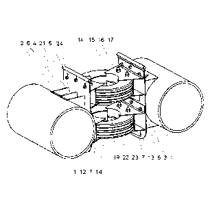
The coupling comprises first gripping members (7) which are connected, facing on one and the same level on corresponding mounting bodies (2), to respective structures, and second gripping members (15) mounted so as to slide vertically on the first gripping members (7) in order to secure pneumatic covers (14) in two diametrically opposed regions thereof with the collaboration of threaded rods (22). The gripping members (7) and (15) provide retention walls (10 and 19) that extend towards the mounting bodies (2) by means of horizontal retention flanges (11 and 20). The second gripping members (15) have walls (17) with holes for the passage of screws during fitting thereof to the mounting bodies (2).


French Abstract

L'invention se rapporte à un accouplement composé de premiers éléments d'accrochage (7) reliés face à face, sur un même niveau, à des éléments de montage correspondants (2) associés à des structures respectives, et de seconds éléments d'accrochage (15) montés à coulissement vertical au-dessus des premiers éléments d'accrochage (7), destinés à assujettir des pneumatiques (14) dans deux régions diamétralement opposées de ces derniers, à l'aide de tiges filetées (22). Les éléments d'accrochage (7) et (15) forment des parois de retenue (10 et 19) qui s'étendent jusqu'aux éléments de montage (2) par l'intermédiaire de ailes de retenue horizontales (11 et 20). Les seconds éléments d'accrochage (15) présentent des parois (17) munies d'orifices destinés au passage de boulons lorsqu'ils sont adaptés aux corps de montage (2).

Claims

Note: Claims are shown in the official language in which they were submitted.


6
CLAIMS:
1. A shock-absorbing coupling for floating structures, which includes two
mounting
bodies to be respectively mounted on components facing each other of adjoining
frames of a
structure, and at least one flexible body placed between said mounting bodies,
wherein it
includes first gripping members respectively connected, facing each other at
the same level,
in each said mounting body and second gripping members respectively mounted
and
vertically slidable in each said mounting body above and overlapping said
first gripping
members;
said first and second gripping members facing each other and able to hold said
tyres,
in horizontal position, which they hold in two diametrically opposite regions,
so that each tyre
in the structure can bend, stretch or twist on their central region; wherein
said first and second gripping members are made up of respective plates with
holes,
provided with retention walls and in their front edge, running vertically
opposite in one and
other members and ending up in respective horizontal retention flanges and
folded inwards,
said first gripping members also comprising lower ribs capable of
collaborating in their
connection with support walls in the mounting bodies and said second gripping
members
comprising fixing walls with holes provided to correspondingly face the
elongated holes in
said support walls of the mounting bodies; and wherein
at least one of said gripping members is provided with at least one retention
wall with
its contour adapted to the external periphery of the tyre to restrain its
expansion.
2. The shock-absorbing coupling for floating structures according to claim
1, wherein the
at least one flexible body includes tyres.
3. The shock-absorbing coupling for floating structures according to claim
2,wherein
said tyres are fixed in said first and second gripping members with the
collaboration of
threaded rods passing through holes, which are respectively facing each other
in the tyres
and in said first and second gripping members.

Description

Note: Descriptions are shown in the official language in which they were submitted.


'CA 02829173 2013-09-05
1
SHOCK-ABSORBING COUPLING FOR FLOATING STRUCTURES
DESCRIPTION
[0001] FIELD OF THE INVENTION
[0002] The invention relates to a shock-absorbing coupling for
floating structures and
is especially intended, although not exclusively, for use in coupling modular
structures to
make up jetties and other support platforms and, more particularly, it is
intended for beds
applied to lamellibranch mollusc farming in rough waters or in the open sea.
It might as
well be used in submerged or submersible structures.
[0003] BACKGROUND OF THE INVENTION
[0004] It is necessary to absorb movement in structures that need to
be adapted to
water movement. Such is the case of jetties or other platforms, either passing-
through or
support platforms, built with independent elements that must be kept together
by means
of couplings which can buffer the joining thereof.
[0005] Moreover, breeding molluscs at ria mouths, in rough waters of
large lakes or in
the open sea where waves can be considerable, requires farming structures to
resist the
battering of the sea and the force of underwater currents during storms, or
the efforts
derived from tugging said structures to their place of use, or both situations
at the same
time. In addition, in known designs of mollusc farming structures, the
breeding ropes
hanging from the structures endure abrupt movements, thus causing the
detachment of
part of the culture.
[0006] The stiffness of these structures, together with the heavy loads
they support,
prevent proper adjustment to the marine environment and, as a better
adjustment to the
environment is required in the facilities and devices for mollusc farming than
in those
designed for fish breeding, it has become necessary to design structures
intended for this
specific type of farming having elongated hollow members or at least with
hollow ends
interconnected with intermediate flexible modules, as disclosed in document
ES2145727.
[0007] Document W08703170, though not intended for mollusc breeding,
discloses a
floating breeding device for fish and the like including at least one breeding
bag which is
carried by a cage equipped with floating bodies, which cage consists of a
three-
dimensional frame consisting of a number of rods composed to polygons, which
rods and
foreseen interconnecting struts are elastically interconnected between at
least some of
the joints.

CA 02829173 2013-09-05
2
[0008 Document EP0358421 discloses the use of a flexible coupling to
join frame
members into a fence structure for fish breeding, the coupling including first
and second
mounting means for mounting to respective frame members adjoining in the
structure and
a flexible body between said first and second mounting means. The rotational
and
translational movement between adjoining frame members is determined by the
material
of the flexible body and by two mechanical stops. The coupling includes a
mechanical
connection between the mounting means in case the flexible body fails.
[0009] OBJECT OF THE INVENTION
[0010] It is an object of this invention to provide a shock-absorbing
coupling for use in
passing through or loading floating structures and in the structures intended
for mollusc
breeding if required. The coupling is to be built so that its use provides
more stability in all
structures and better navigable conditions in those intended for breeding,
increasing their
adaptability above the water surface or submerged, to rough waters or to the
battering of
waters, in order to accomplish better productivity, reducing or removing
culture
detachments caused by water movement.
[0011] The shock-absorbing coupling for floating structures is
intended for easy and
lightweight construction, although strong and elastic enough to absorb,
without structural
deformation, the loads applied in storms and sea currents.
[0012] DESCRIPTION OF THE INVENTION
[0013] The objects are accomplished, according to the invention,
providing a shock-
absorbing coupling for floating structures built with two mounting bodies
adapted to be
respectively inserted in adjoining elements of a structure, and, between them,
a number
of tyres will be placed and kept horizontal when in use. The amount of
couplings to be
added to a structure will vary depending on the size of the required elements
and
structure. Each coupling includes at least one pair of mounting bodies facing
each other,
preferably two pairs, and between each pair, a tyre or other similar flexible
body is placed.
A simplified expression of a mounting body has a retention wall that can be
conventionally connected by one of its sides to an element of the structure so
that it ends
up facing another retention wall equally connected to an adjoining element of
the
structure.
The sides of the retention walls that are not connected to the elements of the
structure
secure support of the gripping members of the tyres.
[0014] More particularly, the shock-absorbing coupling is provided with
first and
second gripping members connected and respectively facing each other at the
same level

,CA 02829173 2013-09-05
3
in each said mounting body, so that, between the first and second gripping
members
connected to one of the mounting bodies facing each other and the first and
second
gripping members respectively mounted in the mounting body facing them, the
tyre is
placed so that it is kept between them in diametrically opposite areas thereof
with the
purpose that the tyres in the shock-absorbing coupling and, therefore, in the
structure
may bend, stretch or twist freely on their central areas absorbing the
movement from
waves and sea currents.
[0015] The first gripping members are preferred to be welded onto the
respective
mounting bodies, whereas the second gripping members are preferred to be
connected
with conventional fastening means, being slidable in vertically elongated
holes foreseen
in each of said mounting bodies, arranged above and overlapping the first
gripping
members, so that the second gripping members can accordingly get closer to and
farther
from the first gripping members in order to secure the tyres in place in the
best possible
way. The joining elements between them being removed, it is possible to access
the tyres
for adding or removing them.
[0016] Moreover, said first and second gripping members are preferred
to be steel
plates made up of a retention wall on its front edge, which runs vertically
opposite in each
gripping member to end up in a respective horizontal retention flange folded
inwards.
Therefore, as the region next to the internal periphery of the tyre close to
the heel is
located between the retention walls and flanges of both gripping members, the
undesired
detachment of the tyre is prevented.
[0017] The plate which makes up the first gripping member includes
lower ribs which
facilitate its welding connection to the support wall in the mounting body.
[0018] The second gripping member is foreseen with an attachment wall
provided
with holes aligned with the elongated holes provided in the support wall of
the mounting
body for passing the fastening elements through.
[0019] In order to restrain tyre expansion, at least any of the first
or second gripping
members is provided with a retention wall, continuous or not, with its contour
adapted to
the external periphery of the tyre.
[0020] To favour tyre behaviour, the invention proposes that each tyre is
fixed,
between said first and second gripping member connected to each mounting body,
by
means of threaded rods passing through the holes respectively provided facing
the tyre
and the gripping members, the rods being secured with nuts on the outside of
the
gripping members.

=
CA 02829173 2013-09-05
4
[0021] BRIEF DESCRIPTION OF THE DRAWINGS
[0022] Going into detail hereinafter, the invention is described in
connection with the
accompanying drawings, which show an example of a preferred non-limiting
embodiment
to be used in a mollusc breeding structure and wherein the shock-absorbing
coupling for
floating structures is preferably illustrated in a position before and after
mounting, in this
model, on two hollow components belonging to structure frames facing each
other:
[0023] Figure us a perspective view of the shock-absorbing coupling
for floating
structures with all its components.
[0024] Figure 2 is a cross-sectional view of the shock-absorbing
coupling for floating
structures mounted with all its components.
[0025] DESCRIPTION OF AN EMBODIMENT OF THE INVENTION
[0026] Generally and in connection with the drawings, a shock-
absorbing coupling for
floating structures is provided, in this embodiment particularly used as a
link between the
modular frames making up said structures to form mollusc breeding structures,
and in
which each of the two mounting bodies (2), which can be added to the
structure, is made
up of a rounded wall (3) to adapt itself to the rounded surface of the hollow
components
(1) of two frames facing each other in the structure of floating beds that can
be
submerged and a flat support wall (4) provided with holes (5), which are
vertically
elongated and arranged in two levels thereof. Ribs (6) keep both walls (3) and
(4)
fastened.
[0027] As shown in the figures, the first gripping member (7), in a top
view, is made
up of a generally trapezoid-shaped plate with holes (8), with its largest side
defined by a
straight edge (9) that helps adapt to the flat support wall (4), the contour
of its smallest
side being curved-concave and vertically extended in an upward direction,
making up a
retention wall (10) that is finished with a horizontal retention flange (11)
folded inwards
into the plate (8), both (10) and (11) being intended to grip an area of the
heel of the tyre
(14) together with, in the example, a retention wall(12). The bottom of said
first gripping
member (7) shows lower ribs (13) that help connecting to the respective
mounting bodies
(2).
[0028] In the embodiment shown in the figures, the second gripping
member (15) is
made up of a plate with holes (16) with a fixing wall (17), also with holes
(18), that
extends vertically in an upward direction in one edge of the plate (16) and
has a retention
wall (19) running vertically in a downward direction on the opposite edge of
the plate (16),
with its contour adapted to the internal periphery of the tyre (14), ending up
in a horizontal
retention flange (20) folded inwards.

, . CA 02829173 2013-09-05
[0029] Conventional fastening members (21), in the example made up
of bolts and
nuts, keep the second gripping members (15) fastened to the support walls (4),
even
though if they get loose, it is possible that the former slide down onto the
latter.
[0030] As it can be observed, in Figure 2, threaded rods (22) are
passed through the
5 plates with holes (8, 16), once the tyres (14) are in place, between
the first (7) and the
second (15) gripping members, fastening being secured by means of nuts (23).
Protection profiles (24) can be used on the sharp edges of the components of
the shock-
absorbing coupling.
[0031] According to the above-said, it is understood that, once the
shock-absorbing
couplings are mounted between the hollow components (1), beams or cross beams
of
two beds, or, where appropriate, of facing modules of the structure for
mollusc breeding
and the latter being in place for use, when the shock-absorbing couplings are
not under
any sea-caused force, the tyres (14) will remain at rest and unaltered. When,
as a result
of water agitation, the shock-absorbing coupling is compressed in the
horizontal axial
direction due to the thrust of the structure or a part thereof, the mounting
bodies (2) get
closer between the gripping members (7) and (15) and the tyres (14) will end
up
elastically compressed in the central region, pushed in by the retention walls
(12). When
the set is pull loaded, the tyres (14) stretch elastically because the gap
between walls
(10) and (19) of the mounting bodies (2) grows bigger. Adjustment to water
movement will
be absorbed by tyre (14) bending as determined by the different inclination
between the
mounting bodies and, therefore, of the gripping members (7) and (15)
respectively
fastened facing each other in the mounting bodies (2).
[0032] The invention is not limited to the embodiment shown herein,
a plurality of
variations within the scope of the claims being possible.

Representative Drawing
A single figure which represents the drawing illustrating the invention.
Administrative Status

2024-08-01:As part of the Next Generation Patents (NGP) transition, the Canadian Patents Database (CPD) now contains a more detailed Event History, which replicates the Event Log of our new back-office solution.

Please note that "Inactive:" events refers to events no longer in use in our new back-office solution.

For a clearer understanding of the status of the application/patent presented on this page, the site Disclaimer , as well as the definitions for Patent , Event History , Maintenance Fee  and Payment History  should be consulted.

Event History

Description Date
Letter Sent 2024-03-08
Common Representative Appointed 2019-10-30
Grant by Issuance 2019-08-20
Inactive: Cover page published 2019-08-19
Inactive: Final fee received 2019-06-26
Pre-grant 2019-06-26
Notice of Allowance is Issued 2019-01-16
Letter Sent 2019-01-16
Notice of Allowance is Issued 2019-01-16
Inactive: Approved for allowance (AFA) 2019-01-08
Inactive: Q2 passed 2019-01-08
Amendment Received - Voluntary Amendment 2018-10-01
Inactive: S.30(2) Rules - Examiner requisition 2018-04-06
Inactive: Report - No QC 2018-03-29
Inactive: IPC deactivated 2017-09-16
Letter Sent 2017-03-17
Inactive: IPC assigned 2017-03-16
Inactive: First IPC assigned 2017-03-16
Inactive: IPC assigned 2017-03-16
Change of Address or Method of Correspondence Request Received 2017-03-03
Request for Examination Requirements Determined Compliant 2017-03-03
All Requirements for Examination Determined Compliant 2017-03-03
Request for Examination Received 2017-03-03
Inactive: IPC expired 2017-01-01
Inactive: Cover page published 2013-10-29
Inactive: First IPC assigned 2013-10-09
Inactive: Notice - National entry - No RFE 2013-10-09
Inactive: IPC assigned 2013-10-09
Application Received - PCT 2013-10-09
National Entry Requirements Determined Compliant 2013-09-05
Application Published (Open to Public Inspection) 2012-09-13

Abandonment History

There is no abandonment history.

Maintenance Fee

The last payment was received on 2019-03-01

Note : If the full payment has not been received on or before the date indicated, a further fee may be required which may be one of the following

  • the reinstatement fee;
  • the late payment fee; or
  • additional fee to reverse deemed expiry.

Please refer to the CIPO Patent Fees web page to see all current fee amounts.

Owners on Record

Note: Records showing the ownership history in alphabetical order.

Current Owners on Record
ESPANOLA DE PLATAFORMAS MARINAS, S.L.
Past Owners on Record
ANDRES QUINTA CORTINAS
Past Owners that do not appear in the "Owners on Record" listing will appear in other documentation within the application.
Documents

To view selected files, please enter reCAPTCHA code :


To view images, click a link in the Document Description column. To download the documents, select one or more checkboxes in the first column and then click the "Download Selected in PDF format (Zip Archive)" or the "Download Selected as Single PDF" button.

List of published and non-published patent-specific documents on the CPD .

If you have any difficulty accessing content, you can call the Client Service Centre at 1-866-997-1936 or send them an e-mail at CIPO Client Service Centre.


Document
Description 
Date
(yyyy-mm-dd) 
Number of pages   Size of Image (KB) 
Drawings 2013-09-05 2 46
Description 2013-09-05 5 267
Representative drawing 2013-09-05 1 30
Claims 2013-09-05 1 51
Abstract 2013-09-05 1 16
Cover Page 2013-10-29 1 50
Claims 2018-10-01 1 45
Representative drawing 2019-07-22 1 12
Cover Page 2019-07-22 1 46
Notice of National Entry 2013-10-09 1 206
Reminder of maintenance fee due 2013-11-12 1 111
Reminder - Request for Examination 2016-11-09 1 117
Acknowledgement of Request for Examination 2017-03-17 1 187
Commissioner's Notice - Maintenance Fee for a Patent Not Paid 2024-04-19 1 560
Commissioner's Notice - Application Found Allowable 2019-01-16 1 163
Amendment / response to report 2018-10-01 4 153
PCT 2013-09-05 18 610
Request for examination 2017-03-03 1 42
Change to the Method of Correspondence 2017-03-03 1 42
Examiner Requisition 2018-04-06 5 223
Final fee 2019-06-26 2 43