Note: Descriptions are shown in the official language in which they were submitted.
CA 02829330 2014-12-10
ROTATIONAL ENERGY HEAT GENERATION APPARATUS AND METHODS
Field
The present subject matter is related to devices for the production of heat,
and
more particularly, to methods and apparatus for generating heat using
rotational energy.
Background
A hydrodynamic heater generates heat by inducing shear within a fluid. The
shear may come in the form of structure that is caused to move within the
fluid. Heat
may be generated by a principle known as fluid resistance heating, in affect,
friction
heating. Heating may also be generated by a principle of direct cavitation
within layers of
liquid. Although the transformation of mechanical energy into thermal energy
via the
hydrodynamic heater is relatively efficient, an increase in energy efficiency
is desirable.
Brief Description of the Drawings
Like reference numbers generally indicate corresponding elements in the
figures.
FIG. 1 is a side cross-sectional view of an embodiment of a hydrodynamic
heater
in accordance with an embodiment;
FIG. 2 is a front view of the stationary member of FIG. 1;
FIG. 3 is a front view of the rotation member of the embodiment of FIG. 1;
FIG. 4 is a side view of another embodiment of a hydrodynamic heater further
comprising a rotation member comprising fluid movement elements;
FIG. 5 is a side cross-sectional view of the hydrodynamic heater of FIG. 1,
further
comprising a first spacing actuator coupled to the stationary member operable
to
translate the stationary member along the X-axis for varying the spacing
between the
fluid driver disk face and the fluid interactive disk face, in accordance with
an
embodiment;
FIG. 6 is a schematic representation of an embodiment of a heater system
comprising a hydrodynamic heater, a fluid handling system, and a motor drive;
1
CA 02829330 2014-12-10
,
FIG. 7 is a side cross-sectional view of an embodiment of a multi-stage
hydrodynamic heater;
FIG. 8 is a schematic diagram of an engine-driven heat generation system, in
accordance with an embodiment;
FIG. 9 is a schematic diagram of another engine-driven heat generation system,
in accordance with another embodiment;
FIG. 10 is a side perspective view of a heating system in accordance with an
embodiment; and
FIG. 11 is a schematic of the fluid handling system associated with the
heating
system of FIG. 10.
Detailed Description
In the following description, embodiments of apparatus and methods will be
disclosed. For purposes of explanation, specific numbers, materials, or
configurations
are set forth in order to provide a thorough understanding of the embodiments.
However,
it will also be apparent to those skilled in the art that the embodiments may
be practiced
without one or more of the specific details, or with other approaches,
materials,
components, etc. In other instances, well-known structures, materials, or
operations are
not shown or described in detail to avoid obscuring the embodiments.
Accordingly, in
some instances, features are omitted or simplified in order to not obscure the
disclosed
embodiments. Furthermore, it is understood that the embodiments shown in the
figures
are illustrative representations and are not necessarily drawn to scale.
Reference throughout this specification to "one embodiment" or "an embodiment"
means that a particular feature, structure, or characteristic described in
connection with
the embodiment is included in at least one embodiment of claimed subject
matter. Thus,
the appearances of the phrase "in one embodiment" or "an embodiment" in
various
places throughout this specification are not necessarily all referring to the
same
embodiment. Furthermore, the particular features, structures, or
characteristics may be
combined in one or more embodiments.
2
CA 02829330 2014-12-10
,
Reference will now be made to embodiments illustrated in the drawings and
specific language which will be used to describe the same. It will
nevertheless be
understood that no limitation of the scope of the invention is thereby
intended. Alterations
and further modifications of the illustrated embodiments and further
applications of the
principles of the invention, as would normally occur to one skilled in the art
to which the
invention relates, are also within the scope of the invention.
FIG. 1 is a side cross-sectional view of an embodiment of a hydrodynamic
heater
2 in accordance with an embodiment. The hydrodynamic heater 2 comprises a
stationary
member 20 and a rotation member 14 disposed proximate the stationary member 20
with
a working fluid therebetween. Rotation of the rotation member 14 about an X-
axis
induces fluid shearing and fluid friction within the working fluid operable to
increase the
temperature of the working fluid.
FIG. 2 is a front view of the stationary member 20 of the embodiment of FIG.
1.
The stationary member 20 comprises a first disk-shaped member 22 having a
plurality of
fluid interactive elements 12. The plurality of fluid interactive elements 12
are disposed
and arranged in a planar, generally circular, spaced-apart, orientation on the
first disk-
shaped member 22 defining a fluid interactive disk face 15, also shown in FIG.
1. The
first disk-shaped member 22 defines an X-axis which is substantially
perpendicular to the
fluid interactive disk face 15.
FIG. 3 is a front view of the rotation member 14 of the embodiment of FIG. 1.
The
rotation member 14 comprises a second disk-shaped member 122 having a
plurality of
fluid driver elements 112 and a shaft 18. The plurality of fluid driver
elements 112 are
disposed and arranged in a planar, generally circular, spaced-apart,
orientation on the
second disk-shaped member 122 defining a fluid driver disk face 115, also
shown in FIG.
1. The shaft 18 is coupled substantially at the center of rotation of the disk-
shaped
member 122. The center of rotation of the disk-shaped member 122 defines an X-
axis
which is substantially perpendicular to the fluid driver disk face 115.
3
CA 02829330 2014-12-10
The shaft 18 is operable to couple with an energy source operable for
imparting
rotation to the shaft 18 so as to rotate the rotation member 14 about the X-
axis.
Examples of a suitable energy source include, but are not limited to, an
electric motor,
hydraulic pump, and internal combustion engine using a drive shaft, power take-
off, or
belt drive, among others.
Referring again to FIG. 1, the fluid driver disk face 115 of the rotation
member 14
is disposed in opposing, substantially parallel, spaced-apart relationship and
substantially coaxial with the fluid interactive disk face 15 of the
stationary member 20
along the X-axis. The distance of separation between the fluid driver disk
face 115 and
the fluid interactive disk face 15 is designated as spacing X1 in FIG. 1. The
space
between and defined by the fluid driver disk face 115 and the fluid
interactive disk face
is referred herein as the fluid interaction space 52. Substantially all of the
heating of
the fluid due to the interaction of the fluid driver elements 112 of the
rotation member 14
and the fluid interactive elements 12 of the stationary member 20 with the
fluid occurs
15 within the fluid interaction space 52.
As the shaft 18 is rotated, the fluid driver elements 112 of the rotation
member 14
move relative to the fluid interactive elements 12 of the stationary member
20. Fluid
disposed between the fluid driver disk face 115 and the fluid interactive disk
face 15 in
the fluid interaction space 52 is acted upon hydrodynamically so as to induce
heating
therein. Fluid shear and friction causes the temperature of the working fluid
to increase.
The hydrodynamic heater 2 also comprises a housing 30 defining a fluid cavity
32
into which the stationary member 20 and the rotation member 14 are disposed.
The
housing 30 defines a fluid inlet 34 and a fluid outlet 36 operable to provide
fluid ingress
and egress, respectively. The flow of working fluid is substantially from the
fluid inlet 34,
through the space between the fluid driver disk face 115 and the fluid
interactive disk
face 15 and out through the fluid outlet 36. The working fluid may be driven
through the
housing 30 by an external pump (not shown) in accordance with an embodiment or
by
the movement of the fluid driver elements 112 in accordance with another
embodiment,
but not limited thereto.
4
CA 02829330 2014-12-10
It is appreciated that the stationary member 20 may comprise one or more fluid
interactive elements 12. The fluid interactive elements 12 are operable to
cooperate with
the one or more fluid driver elements 112 so as to induce fluid shear operable
to heat the
fluid therebetween. The fluid interactive elements 12 and the fluid driver
elements 112,
as provided in the embodiment of FIG. 1, are concave by way of example. In
other
embodiments, the fluid interactive elements 12 and the fluid driver elements
112 are
convex or fan-blade shaped suitable for the particular purpose. The fluid
interactive
elements 12 and the fluid driver elements 112 may be substantially similar in
shape or
may be of different shapes.
One fluid driver element 112 may be sufficient to induce the necessary fluid
movement to provide shearing that creates friction heating of the working
fluid. It is
appreciated that when reference is made to a plurality of fluid driver
elements 112, it
applies also to embodiments comprising one fluid driver element 112.
The amount of fluid shear, and thus the amount of heating of the fluid induced
by
the rotation of the fluid driver elements 112, is determined, at least in
part, by one or
more of the speed of rotation of the rotation member 14, the spacing X1 which
is the
distance of separation between the fluid driver disk face 115 and the fluid
interactive disk
face 15, and the speed of the working fluid into and out of the fluid inlet 34
and the fluid
outlet 36, respectively. The properties of the working fluid also determine,
at least in
part, the degree of heat induced by the fluid movement. The properties of the
fluid
include, but are not limited to, density, viscosity, and heat capacity, among
others.
It is appreciated that heat output of the hydrodynamic heater 2 may also
depend
on the size of the apparatus, such as, but not limited to the diameter of the
fluid driver
disk face 115 and the fluid interactive disk face 15. Also, and not limited
thereto, the size
and number of fluid driver elements 112 and fluid interactive elements 12 may
also
determine, at least in part, the heat output. Also, and not limited thereto,
the number of
rotation members 14 and stationary members 20 may also determine, at least in
part, the
heat output of the hydrodynamic heater 2.
5
CA 02829330 2014-12-10
The fluid inlet 34, the space between the fluid driver disk face 115 and the
fluid
interactive disk face 15, and the fluid outlet 36 define a fluid path
(indicated by the arrows
shown on FIG. 1). A working fluid having a lower temperature enters the fluid
inlet 34, is
acted upon by the interaction of the rotation member 14 and the stationary
member 20
thereby heating the working fluid, and the working fluid having a higher
temperature exits
the housing cavity 32 through fluid outlet 36. Thus, as the rotation member 14
rotates,
the fluid absorbs at least a portion of the heat generated by the shearing of
the working
fluid. The working fluid may thus be used to transport heat to another
location.
In accordance with an embodiment, an external fluid path 132 external to the
housing 30 is established between the fluid outlet 36 and the fluid inlet 34
such that the
fluid circulates from the fluid outlet 36, through the external fluid path
132, into the fluid
inlet 34, and through the fluid cavity 32, as shown in FIG. 1. The external
fluid path 132
may be facilitated by any suitable conduit operable to control the transport
of the working
fluid, such as, but not limited to, pipe and hose. In accordance with
embodiments,
connectors couple a conduit to the fluid inlet 34 and the fluid outlet 36 so
as to transfer
the working fluid out of the hydrodynamic heater 2 so as to transfer the heat
to an
external location from the hydrodynamic heater 2.
The external fluid path 132 may include a heat exchanger 72 or other suitable
apparatus operable to exchange heat to a target environment as will be
discussed below.
Such target environment may include, but not limited to, a fluid path of a fan
so as to
heat air, such as a grain dryer, and heat hoses to heat and defrost frozen
ground onto
which the hose is placed.
The radial and axial placement of the fluid driver elements 112 and the fluid
interactive elements 12 about the fluid driver disk face 115 and the fluid
interactive disk
face 15, respectively, as shown in FIGs. 2 and 3 is exemplary only. Placement
of the
fluid driver elements 112 and the fluid interactive elements 12 about the disk-
shaped
member 22 in other arrangements, orientations, spacing, among other things, in
planar
relationship or otherwise, is anticipated suitable for a particular purpose of
imparting
shear to a working fluid so as to induce heating within the working fluid.
Furthermore,
6
CA 02829330 2014-12-10
. .
the fluid driver elements 112 and the fluid interactive elements 12 need not
be of the
same size, shape, or orientation, among other things.
In accordance with the embodiment of FIG. 1, the rotation member 14 is caused
to rotate about the X-axis while the stationary member 20 is held stationary.
It is
understood that relative motion between the stationary member 20 and the
rotation
member 14 can be produced, in accordance with embodiments, by the above
mentioned
configurations, and by other configurations, such as, but not limited to,
rotation of both
the stationary member 20 and rotation member 14 at different rates in the same
direction, and rotation of both the stationary member 20 and rotation member
14 in
lo opposite directions.
The rate of heat generation in the hydrodynamic heater 2 in accordance with
embodiments depends, at least in part, on the hydrodynamic properties of the
stationary
member 20 and the rotation member 14 as well as the relative rotation speed
between
the two.
Therefore, for applications wherein a high rate of heat generation is
desirable, it
may be desirable that the rotation member 14 have a relatively high relative
rotation
speed with respect to the stationary member 20. The degree of fluid shear
produced by
the fluid driver elements 112 and the fluid interactive elements 12 is related
to the
relative rotation speed.
In addition, the maximum temperature that can be generated by a hydrodynamic
heater 2 according to embodiments herein, depends, at least in part, on the
heat
capacity of the fluid 12.
The rotation member 14 comprises any material suitable for the particular
purpose. Suitable materials include, but are not limited to, copper, aluminum,
alloys of
copper, alloys of aluminum, and other metallic or non-metallic materials.
FIG. 1 shows the hydrodynamic heater 2 in simplified schematic form for
clarity. It
is understood that additional structure may be present to provide structural
support for
containment and alignment of the stationary member 20, rotation member 14, and
shaft
18. By way of example, but not by way of limitation, a fluid seal between the
shaft 18
7
CA 02829330 2014-12-10
' .
and the housing 30 may be required to contain the fluid from leaking though
the
penetration of the housing 30 to accommodate the shaft 18. Also, but not by
way of
limitation, the stationary member 20 may be supported by structure within the
housing 30
to ensure alignment with the rotation member 14.
Again referring to FIG. 1 of the hydrodynamic heater 2, the fluid path 16 is
defined
so that at least a portion thereof extends between the fluid interactive disk
face 15 of the
stationary member 20 and the fluid driver disk face 115 of the rotation member
14 in
accordance with embodiments. The fluid path 16 extends substantially parallel
with
respect to the fluid driver disk face 115 and the fluid interactive disk face
15.
Suitable working fluids for the particular purpose include, but are not
limited to,
liquid fluids such as water, propylene glycol, among others.
FIG. 4 is a side view of another embodiment of a hydrodynamic heater 2 further
comprising a rotation member 14 comprising fluid movement elements 38, in this
embodiment, in the form of fins, depending from the fluid driver disk face 115
operable to
engage with a fluid for driving fluid through the fluid cavity 32. The fluid
movement
elements 38 comprise a plurality of fins or blades. The driving action of the
fluid is
provided by the rotation of the rotation member 14 with the fins moving the
fluid. Thus,
the speed of operation of the fluid movement elements 38 depends on the speed
of
motion of the rotation member 14, and likewise the rate of fluid flow within
the fluid path
16. In this embodiment, the fluid driver elements 112 are operable to produce
the fluid
shear while the fluid movement elements 38 move the fluid through the fluid
cavity 32.
In accordance with another embodiment, fluid movement elements 38 are also
operable to induce fluid shear in the working fluid. In yet other embodiments,
fluid
movement elements 38 in the form of fins disposed on the fluid interactive
disk face 15 of
the stationary member 20 induces fluid shear as the working fluid is driven
past the fluid
interactive disk face 15 by the rotation member 14.
In accordance with other embodiments, the working fluid is driven through the
flow path by an external energy source, such as, but not limited to, a pump.
5
CA 02829330 2014-12-10
It is appreciated that the temperature to which working fluid passing through
the
fluid path 16 is heated depends, at least in part, on the rate of rotation of
the rotation
member 14 and the amount of fluid shear produced. Also, the temperature of the
fluid
depends, at least in part, on the rate at which the fluid moves through the
fluid path 16,
that is, on how long the fluid is undergoing fluid shear. Further, the
temperature of the
fluid depends, at least in part, on the efficiency of the fluid driver
elements 112 and the
fluid interactive elements 12 to produce fluid shear so as to induce heating
of the fluid.
The performance parameters, such as, but not limited to, the rate of heat
generation, rate of fluid flow, and fluid temperature, may be independent of
one another
as described in some embodiments herein. A hydrodynamic heater 2 in accordance
with
embodiments may be used to produce a specific temperature of working fluid in
combination with a specific rate of fluid flow. Any two of the three
parameters may be
controlled independently of one another in accordance with at least some
embodiments
disclosed herein.
The energy source used to drive the rotation of the shaft 18 may comprise any
suitable means. In accordance to embodiments, the shaft 18 may be operable to
be
coupled to a power take-off found on some motor vehicles, such as, but not
limited to,
many tractors, other agricultural vehicles, and heavy work vehicles. In such
vehicles,
some of the mechanical driving force generated by an engine is transferred to
the power
take-off to impart rotation, such as to the shaft 18. Conventional power take-
offs include
a rotatable coupling or other movable component which may be engaged with a
linkage
to impart rotation to the shaft 18.
In other embodiments, the shaft 18 comprises a hydraulic linkage. Certain
vehicles include hydraulic systems, such as, but not limited to, for actuating
a snow plow
or shovel blade, for tipping a truck bed, or for operating a fork lift. The
hydraulic system
may be operable to couple with supplemental equipment, such as a hydraulic
motor, with
suitable linkage operable to couple with the shaft 18, to provide power
thereto. Hydraulic
systems and hydraulic linkages are known in the art, and are not described in
detail
herein.
9
CA 02829330 2014-12-10
Various embodiments are anticipated so as to control the rate of heat output
of
the hydrodynamic heater 2. In accordance with embodiments, the temperature
change
of the working fluid within the hydrodynamic heater 2 is directly related to
the heat energy
(BTU) generated in the working fluid and the flow rate of the working fluid.
Adjusting one
or both of the heat energy (BTU) generated in the working fluid and the flow
rate
provides a predetermined amount of fluid with a predetermined temperate
exiting the
hydrodynamic heater 2.
FIG. 5 is a side cross-sectional view of the hydrodynamic heater 2 of FIG. 1,
further comprising a first spacing actuator 26 coupled to the stationary
member 20
operable to translate the stationary member 20 along the X-axis for varying
the spacing
X1 between the fluid driver disk face 115 and the fluid interactive disk face
15, in
accordance with an embodiment. In contrast to the embodiment of FIG. 4 wherein
the
spacing X1 between the stationary member 20 and the rotation member 14 is
fixed, the
spacing X1 is variable in the embodiment of FIG. 5, wherein the spacing X1 may
be
changed either during operation or when not in operation. During operation,
when the
spacing X1 is reduced, fluid shear will increase and thus the temperature of
working fluid
will increase, and as the spacing X1 is increased, fluid shear will decrease
and thus the
temperature of working fluid will decrease.
In accordance with another embodiment, the hydrodynamic heater 2 further
comprises a second spacing actuator 44 coupled to the rotation member 14
operable to
translate the rotation member 14 along the X-axis for varying the spacing X1
between
the fluid driver disk face 115 and the fluid interactive disk face 15, as
shown in HG. 5.
The spacing actuator 44 varies the spacing X1 between the fluid driver disk
face 115 and
the fluid interactive disk face 15 along the X-axis.
It is anticipated that the first spacing actuator 26 and the second spacing
actuator
44 may be used in combination to vary the spacing X1 between the fluid driver
disk face
115 and the fluid interactive disk face 15 along the X-axis.
The degree of fluid interaction with the fluid driver elements 112 and the
fluid
interactive elements 12 depends, at least in part, on the spacing X1 between
the fluid
driver disk face 115 and the fluid interactive disk face 15. A change in the
spacing X1
CA 02829330 2014-12-10
between the fluid driver disk face 115 and fluid interactive disk face 15
changes the
degree of fluid shear, and thus the rate at which heat is generated in the
working fluid.
Reducing the spacing X1 between the fluid driver disk face 115 and fluid
interactive disk face 15 increases the degree of fluid interaction between the
fluid driver
elements 112 and the fluid interactive elements 12, thus increasing the fluid
shear and
thus heating of the fluid. Increasing the spacing X1 between the fluid driver
disk face
115 and fluid interactive disk face 15 reduces the degree of fluid shear by
the fluid driver
elements 112 and the fluid interactive elements 12, thus reducing the heating
of the
rotation member 14.
In embodiments wherein it is desirable to enable a high range of variability
in the
rate of heat generation, it is desirable that the range of possible values for
the spacing
X1 between the fluid driver disk face 115 and fluid interactive disk face 15
be relatively
large.
The spacing X1 between the fluid driver disk face 115 and fluid interactive
disk
face 15 is a parameter that is independent of the rate of fluid flow through
the fluid
interaction space 52 and the rate of rotation of the rotation member 14. Thus,
the rate of
heat generation of the hydrodynamic heater 2 is adjustable by varying the
spacing X1
without changing the rate of rotation of the rotation member 14.
In accordance with an embodiment, the rate of heat generation of the
hydrodynamic heater 2 is adjustable by controlling one or more of the rate of
rotation of
the shaft 18, the spacing X1, and the rate of fluid flow through the fluid
interaction space
52. In an embodiment, the spacing actuator 26 is used to facilitate adjustment
of the
spacing X1 while the hydrodynamic heater 2 is generating heat.
A variety of actuators are suitable for use as the first spacing actuator 26
and the
second spacing actuator 44. In an embodiment, as illustrated in FIG. 5, the
spacing
actuator 26 is a linear actuator engaged with the stationary member 20 to move
it toward
or away from the rotation member 14, thereby adjusting the spacing from X1.
11
CA 02829330 2014-12-10
In an embodiment, the spacing actuator 26 is a manual actuator, such as, but
not
limited to, a threaded screw controlled by a hand-turned knob. In other
embodiments,
the spacing actuator 26 is a powered actuator, such as, but not limited to, an
electrically
or hydraulically driven mechanism. In accordance with another embodiment, one
or both
of the stationary member 20 and rotation member 14 may be coupled to a shaft
comprising helical thread, wherein the location of the stationary member 20
and rotation
member 14 on the shaft, and thus the spacing X1 between the stationary member
20
and the rotation member 14 may be changed.
Referring again to FIG. 5, the hydrodynamic heater 2 further comprises a
controller 138. The controller 138 is in communication with the first spacing
actuator 26
and the second spacing actuator 44 so as to control the spacing X1. The
controller 138
may also be in communication with the shaft 18, so as, by way of example, but
not
limited thereto, to control the speed of rotation of the rotation member 14,
and therefore,
the fluid driver elements 112, which derive their motion from the shaft 18,
wherein the
output of the motive device driving the shaft 18 is variable and controllable.
The controller 138 in FIG. 5 may thus control the rate of heat generation by
controlling the spacing X1, and may also control the speed of rotation of the
rotation
member 14. By controlling these two parameters independently the temperature
of the
working fluid may also be controlled as described previously.
A variety of devices are suitable for use as a controller 138, including, but
not
limited to, microprocessor-based controllers. Controllers are known in the art
and are not
described further herein.
It is appreciated that the heat output may be controlled is a variety of ways.
By
way of example, but not limited thereto, the fluid flow of the working fluid
through the
hydrodynamic heater 2 and the speed of the rotation member 14 may be increased
or
decreased suitable for producing a particular heat output. By way of example,
a
decreased fluid flow in combination with a decreased speed of rotation of the
rotation
member 14 may maintain a predetermined temperature at the output 36.
12
CA 02829330 2014-12-10
. ,
Although the embodiment in FIG. 5 shows the controller 38 in communication
with
various sensors, such as, but not limited to, temperature sensor 40, fluid
flow rate sensor
42, and drive speed sensor 48, it is emphasized that this is exemplary only.
In other
embodiments, the controller 138 controls the operation of the hydrodynamic
heater 2
without sensors or data therefrom. In embodiments, the controller 138
comprises stored
data and/or a pre-calculated algorithm, based on, among other things, the
design of the
hydrodynamic heater 2 and the performance of similar hydrodynamic heaters 2.
The
controller 138 may control the hydrodynamic heater 2 to produce the desired
level of
heat generation, working fluid temperature, and/or rate of fluid flow, without
the need for
active sensors to monitor the parameters of the hydrodynamic heater 2.
The embodiment in FIG. 5 includes a fluid temperature sensor 40 for sensing
the
temperature of working fluid moving along the fluid path 16. It also includes
a fluid flow
rate sensor 42 for sensing the rate of fluid flow through the fluid path 16.
It further
includes a drive speed sensor 48 for sensing the rate at which the rotation
member 14 is
rotated by the shaft 18. The controller 138 is in communication with each of
the fluid
temperature sensor 40, fluid flow rate sensor 42, and drive speed sensor 48.
Based on data from the fluid temperature sensor 40, fluid flow rate sensor 42,
and
drive speed sensor 48, the controller 138 may adjust the speed of the rotation
member
14, the speed of the fluid driver 34, and/or the spacing X1, so as to control
heat
generation, working fluid temperature, and/or fluid flow.
It is emphasized that the arrangement of the fluid temperature sensor 40,
fluid
flow rate sensor 42, and drive speed sensor 48, as shown, is exemplary only.
It is not
necessary for a particular embodiment to include sensors at all, or to include
each of the
fluid temperature sensor 40, fluid flow rate sensor 42, and drive speed sensor
48, shown
in FIG. 5. In other embodiments, other sensors are included in the
hydrodynamic heater
2 in addition to or in place of those shown.
In an embodiment, the hydrodynamic heater 2 comprises an additional sensor
operable to sense the spacing X1 between the stationary member 20 and the
rotation
member 14.
13
CA 02829330 2014-12-10
A variety of sensors are suitable for use in a hydrodynamic heater 2 according
to
embodiments, depending upon the particulars of the specific embodiment of the
hydrodynamic heater 2 and the type of information that is to be sensed.
Sensors are
known in the art and are not described further herein.
FIG. 6 is a schematic representation of an embodiment of a heater system 1
comprising a hydrodynamic heater 2, a fluid handling system 70, and a motor
drive 64.
The fluid handling system 70 comprises a pump 62 and a heat exchanger 72
coupled to
the hydrodynamic heater 2 via plumbing 73. The pump 62 is operable to
circulate fluid
through the hydrodynamic heater 2 and the heat exchanger 72. The pump drives
the
fluid through the fluid inlet 34 through the hydrodynamic heater 2 and through
the outlet
36 to the fluid handling system 70, through the heat exchanger 72 to exchange
heat with
a target environment, and back to the pump 62 to complete the cycle.
The motor drive 64 is coupled to the shaft 18 of the hydrodynamic heater 2
operable to rotate the rotation member 14 within the hydrodynamic heater 2 and
therefore heat the working fluid circulating through the hydrodynamic heater
2.
The fluid handling system 70, which includes the external fluid path 132
external
to the housing 30, includes the heat exchanger 72 operable to heat a target
environment.
Such target environment may include, but not limited to, a fluid path of a fan
so as to
heat air, such as a grain dryer, and liquid hoses to heat and defrost frozen
ground under
which the hose is placed.
FIG. 7 is a side cross-sectional view of an embodiment of a multi-stage
hydrodynamic heater 6. The embodiment shown in FIG. 1 has one pair of rotation
member 14 and stationary member 20. Embodiments of hydrodynamic heater 2 may
be
scaled by the use of additional rotation members 14 and stationary members 20.
The
embodiment of FIG. 7 comprises an arrangement with three rotation members 14a-
c and
two stationary members 20a,b. It is noted that the number of rotation members
14 and
stationary members 20 is exemplary only, and that other numbers and
arrangements
may be suitable for a particular purpose. It is also appreciated that each
stationary
member 20 may comprise a first disk-shaped member 22 having a plurality of
fluid
interactive elements 12 on each of the two sides of the stationary member 20,
and that
14
CA 02829330 2014-12-10
each rotation member 14 may comprise a second disk-shaped member 122 having a
plurality of fluid driver elements 112 on each of the two sides of the
rotation member 14.
It is appreciated that heat output may be controlled by selective activation
and
deactivation (rotation or stationary) of individual rotation members 14.
FIG. 8 is a schematic diagram of an engine-driven heat generation system 100,
in
accordance with an embodiment. The engine-driven heat generation system 100
provides heat to external applications via a working fluid supplied to a
suitable external
heat exchanger 126 as described below. The engine-driven heat generation
system 100
comprises an internal combustion engine 110, a hydrodynamic heater 2, such as,
but not
limited to, the embodiment of FIG. 1, and a fluid handling system 130. A
driveshaft 18
from the engine 110 rotates the fluid driver element within the hydrodynamic
heater 2
which in turn heats the working fluid.
The fluid handling system 130 comprises a working fluid handling system 120,
an
engine cooling system 112, and an exhaust system 129. The working fluid
handling
system 120 comprises a fluid reservoir 121, a manifold flow control 122, an
exhaust heat
exchanger 123, a coolant heat exchanger 124, and one or more circulating pumps
127,
all in fluid communication operable to circulate the working fluid therein.
The manifold
flow control 122 is operable to direct the working fluid to the hydrodynamic
heater 2, the
exhaust heat exchanger 123, and the coolant heat exchanger 124.
The heat generated by the hydrodynamic heater 2 is transferred to the working
fluid passing within the hydrodynamic heater 2. The working fluid is collected
in the fluid
reservoir 121 and either directed again through the manifold flow control 122
or directed
to an external heat exchanger 126 by way of an external manifold 125, or a
combination
thereof. The external manifold 125 is operable to provide one or more fluid
take-offs to
supply the heated working fluid and return cooled working fluid to/from one or
more
external heat exchangers 126.
CA 02829330 2014-12-10
The engine cooling system 112 comprises a coolant reservoir 114 for a coolant
fluid in fluid communication with the engine 110 and the coolant heat
exchanger 124.
The coolant fluid circulates within the engine 110, wherein the heat from the
structure of
the engine 110 is transferred to the coolant fluid and subsequently
transferred to the
working fluid in the coolant heat exchanger 124. In this way, the heat from
the engine
110 as well as the heat from the hydrodynamic heater 2 is used to heat the
working fluid.
The engine 110 produces hot exhaust gas as a product of combustion which is
directed external to the engine 110 by an exhaust manifold 128. The exhaust
system 129
comprises the exhaust heat exchanger 123 which is in fluid communication with
the
exhaust manifold 128 and is operable to transfer the heat from the exhaust of
the engine
110 to the working fluid. In this way, the heat from the exhaust as well as
the heat from
the hydrodynamic heater 2 and engine cooling system 112 is used to heat the
working
fluid.
The engine-driven heat generation system 100, therefore, utilizes the heat of
the
structure of the engine 110 and the heat from the exhaust of the engine 110 to
augment
the heat from the hydrodynamic heater 2 to efficiently provide a heated
working fluid to
the external heat exchanger 126.
It is appreciated that a variety of configurations of an engine-driven heat
generation system may be utilized, depending on engineering design preferences
and
constraints. FIG. 9 is a schematic diagram of another engine-driven heat
generation
system 200, in accordance with another embodiment. The engine-driven heat
generation
system 200 comprises an internal combustion engine 110, a hydrodynamic heater
2,
such as, but not limited to, the embodiment of FIG. 1, and a fluid handling
system 230.
The configuration and function is substantially similar to the embodiment of
FIG. 8, but
this embodiment comprises an engine 110 having two exhaust manifolds 128a,
128b,
two exhaust heat exchangers 123a, 123b in fluid communication with respective
exhaust
manifolds 128a, 128b, and separate external manifolds, a supply manifold 125a
and a
return manifold 125b.
The applications for utilizing the heat generated by the engine-driven heat
generation system 100, 200 are vast. The working fluid is heated to a
predetermined
16
CA 02829330 2014-12-10
. .
temperature suitable for a particular purpose. It is anticipated that most any
application
that utilizes the transfer of heat via a heat exchanger supplied by a heated
working fluid
would be suitable for use with the engine-driven heat generation system 100,
200.
In an embodiment, the heated working fluid is passed through a heat exchanger
that is part of a forced-air ventilation system to provide heated air to a
building. In
another embodiment, the working fluid is passed through hoses that are laid
out on the
ground and covered with a covering so as to heat the ground, such as to thaw
out frozen
ground for excavation. In yet another application, the working fluid is passed
through a
heat exchanger of a hot water supply system that is submerged in a tank of
water so as
to heat the water for use. These are but a few of the vast number of
applications suitable
for use with the engine-driven heat generation system 100, 200.
The engine-driven heat generation system 100, 200 realizes significantly
improved efficiencies over conventional hydrodynamic heaters by the
utilization of the
heat captured from the engine exhaust and the heat captured from the engine
cooling
system that are added to the heat generated by the hydrodynamic heater.
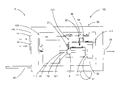
FIG. 10 is a side perspective view of a heating system 8 in accordance with an
embodiment. FIG. 11 is a schematic of the fluid handling system 225 associated
with the
heating system 8 of FIG. 10. The heating system 8 is operable for providing
heated air
suitable for a particular purpose, such as, but not limited to, heating the
interior of a
building and drying grain.
The heating system 8 comprises an internal combustion engine 110, an air
handling system 35, and a hydrodynamic heater 2, all contained in an enclosure
140 on
a trailer 99. The air handling system 35 is operable to draw in air external
to the
enclosure 140 via to air intakes 93, and exhaust air out of the enclosure 140
via an air
outlet 39.
17
CA 02829330 2014-12-10
The internal combustion engine 110 is coupled to an engine cooling system 112.
The engine cooling system 112 comprises a coolant reservoir (not shown) for a
coolant
fluid in fluid communication with the engine 110 and a coolant heat exchanger
124. The
coolant fluid circulates within the engine 110, wherein the heat from the
structure of the
engine 110 is transferred to the coolant fluid and subsequently transferred to
the working
fluid in the coolant heat exchanger 124.
The engine 110 produces hot exhaust gas as a product of combustion which is
directed external to the engine 110 by an exhaust manifold (not shown). The
exhaust
system 129 comprises the exhaust heat exchanger 80 which is in fluid
communication
with the exhaust manifold (not shown) and is operable to transfer the heat
from the
exhaust of the engine 110 to the working fluid.
An engine drive shaft 118 is coupled to the shaft 18 of the hydrodynamic
heater 2
operable to rotate the rotation member 14 within the hydrodynamic heater 2 and
therefore heat the working fluid circulating through the hydrodynamic heater
2.
The working fluid circulates through the fluid handling system 225 as
represented
in FIG. 11. The fluid handling system 225 comprises a reservoir 121, a pump
127, an
exhaust heat exchanger 80, coupling for the hydrodynamic heater 2, and an air
heat
exchanger 126. The fluid handling system 225 provides a circulatory loop
therethrough.
Referring to FIG. 11, the working fluid is drawn from a reservoir 121 by a
pump 127. The
pump 127 is coupled to a splitting manifold 122a that is in fluid
communication with fluid
inlets of the hydrodynamic heater 2 and the exhaust heat exchanger 80. The
working
fluid is heated within the hydrodynamic heater 2 and the exhaust heat
exchanger 80.
The heated fluid is recombined by a second manifold 122b that is in fluid
communication
with the fluid outlets of the hydrodynamic heater 2 and the exhaust heat
exchanger 80.
The working fluid is supplied to an air heat exchanger 126 that is operable to
exchange
heat with an air flow. The working fluid is returned to the reservoir 121.
18
CA 02829330 2014-12-10
=
Referring to FIG. 10, the air handling system 35 comprises a blower. The air
handling system 35 is operable to draw in air from the intakes 93 through the
coolant
heat exchanger 124 such that the air absorbs heat from the coolant heat
exchanger 124.
The air is drawn into a blower inlet 37 with the air exhausted through the air
heat
exchanger 126 and the blower outlet 39 such that the air absorbs heat from the
air heat
exchanger 126. The blower outlet 39 may be provided with suitable conduit to
direct the
heated air for a particular purpose.
Heat from the engine exhaust, via the exhaust heat exchanger 80 and heat from
the hydrodynamic heater 2, as well as heat from the engine cooling system 112
via the
coolant heat exchanger 124, is used to heat air driven by the air handling
system 35.
It is appreciated that air may also pass by the parts of the engine 110 that
are at
elevated temperature picking up heat before reaching the air heat exchanger
126, and
therefore contribute to the overall heat output of the heating system 8.
The trailer 99 is operable to transport the heating system 8. The trailer 99
is
operable to be hitched to a vehicle for movement from location to location.
It is appreciated that the heating of the air is dependent in part on the
speed of
rotation of the driveshaft from the engine 110 driving the rotation member 14
within the
hydrodynamic heater 2. Since the embodiment of FIG. 10 also utilizes heat
obtained
from the engine 110 by way of the engine cooling system 112 and the exhaust
system
129, as the driveshaft speed is increased, the heat rejected by the engine,
and thus
available to heat the air will also increase.
In accordance with an embodiment, the heater system 8 further comprises a
temperature controller. The temperature controller comprises a temperature
sensor that
is operable to monitor either the output air at the blower outlet 39 or the
ambient air in the
space being heated by the air coming from the blower outlet 39. An operator
may input a
desired temperature output or ambient temperature and the controller is
operable to
determine a suitable engine speed operable to maintain the operator desired
temperature.
19
CA 02829330 2014-12-10
,
= .
Although specific embodiments have been illustrated and described herein for
purposes of description of the preferred embodiment, it will be appreciated by
those of
ordinary skill in the art that a wide variety of alternate and/or equivalent
implementations
calculated to achieve the same purposes may be substituted for the specific
embodiments shown and described without departing from the scope of the
present
invention. Those with skill in the art will readily appreciate that the
present invention may
be implemented in a very wide variety of embodiments.
Persons skilled in the art will recognize that many modifications and
variations are
possible in the details, materials, and arrangements of the parts and actions
which have
been described and illustrated in order to explain the nature of this
invention. The scope
of the claims should not be limited by particular embodiments set forth
herein, but should
be construed in a manner consistent with the Specification as a whole.