Note: Descriptions are shown in the official language in which they were submitted.
CA 02829610 2013-10-09
Voi,
1
,
A SYSTEM FOR CAPTURING OF CO2 FROM PROCESS GAS
Technical Field
5 The present invention relates to a system for capturing of CO2 from a
process gas.
The present invention further relates to a method for capturing of CO2
from a process gas.
10 Background art
There is a general aim to capture the CO2 in gases generated in power
generation systems fuelled with for example fossil fuels, gas, or wood to
make the process more environmentally friendly and to reduce the effect of
global warming. The captured CO2 gas may then be compressed and
15 transported to be stored in a suitable place, for example in deep
geological
formations or deep ocean masses. There are several technologies known to
remove CO2 from the flue gas generated such as by absorption, adsorption,
membrane separation, and cryogenic separation.
Dry processes for separation of carbon dioxide from gas mixtures may
20 utilize metal oxides as sorbent. The metal oxide may form metal
carbonate at
high temperatures with carbon dioxide present. The carbon dioxide may be
released from the metal carbonate under the reformation of the metal oxide.
Problems associated with the use of metal oxides as adsorbents for carbon
dioxide includes sintering of the adsorbents resulting in reducing the
25 efficiency of the sorbents, and if sulfur is present in the gas, sulfur
carbonate
may be formed which may reduce the efficiency of the sorbents.
One dry process for separation of carbon dioxide from gas mixtures by
use of a metal oxide sorbent is disclosed in WO 2009/148334 Al. The
disclosed process incorporates regeneration of the carbon dioxide capture
30 capacity of the metal oxide.
It is difficult to obtain efficient regeneration of sorbents for carbon
dioxide capturing according to prior art.
CA 02829610 2013-10-09
a.
2
'
Summary of the invention
Purposes of the present invention include providing solutions to
problems identified with regard to prior art.
The present system and method allow for efficient capturing of CO2
from a process gas with efficient regeneration of sorbent material able to
capture the CO2 present in process gas.
According to a first aspect of the present invention there is provided a
system for capturing CO2 from a process gas, the system comprising a first
reactor arranged to receive a stream of process gas and a particulate sorbent
material comprising calcium oxide able to capture the CO2 present in the
process gas such that calcium carbonate is formed, the first reactor
comprising means for discharging CO2 depleted process gas, a first portion of
particulate sorbent material having captured CO2, and a second portion of
particulate sorbent material having captured CO2; a second reactor arranged
to receive the first portion of particulate sorbent material from the first
reactor,
the second reactor comprising heating means arranged to cause release of
CO2 from the particulate sorbent material by decarbonation of the calcium
carbonate to form calcium oxide, the second reactor further comprising
means for returning the first portion of particulate sorbent material to the
first
reactor and means for discharging a CO2 rich gas stream; and a third reactor
arranged to receive the second portion of particulate sorbent material from
the first reactor, the third reactor comprising means for supplying H20 to the
second portion of particulate sorbent material to hydrate at least a part of a
remaining portion of calcium oxide of the second portion of particulate
sorbent
material to form calcium hydroxide, the third reactor further comprising means
for returning the second portion of particulate sorbent material to the first
reactor.
To hydrate at least a part of a remaining portion of calcium oxide of the
second portion of particulate sorbent material to form calcium hydroxide
results in efficient regeneration of sorbent material. Hydration result in
swelling of the sorbent material, thus hydration may act in removing from the
sorbent material compounds, such as for example CaSO4, which otherwise
may block access to CaO of the sorbent material. The third reactor arranged
to receive the second portion of particulate sorbent material from the first
reactor results in efficient regeneration of sorbent material.
CA 02829610 2013-10-09
3
=
=
According to one embodiment, the first reactor may be a carbonator
reactor, or a reactor where carbonization reactions may occur, the second
reactor may be a calciner reactor, or a reactor where calcination reactions
may occur, and the third reactor may be a hydrator reactor, or a reactor
where hydration reactions may occur.
According to one embodiment, the first reactor may be a circulating
fluidized carbonator reactor, the second reactor may be a circulating
fluidized
calciner reactor, and the third reactor may be a hydrator reactor.
According to one embodiment, the process gas may be flue gas. The
flue gas may, for example, be from the combustion of coal, oil, natural gas,
industrial and domestic waste and peat, for example in power plants.
According to one embodiment, the third reactor may be arranged to
operate at a lower temperature than the first reactor, and the second reactor
may be arranged to operate at a higher temperature than the first reactor.
According to one embodiment, the system may further comprise
means for cooling the second portion of the particulate sorbent material prior
to entering the third reactor.
According to one embodiment, the system may further comprise
means for heating the second portion of the particulate sorbent material prior
to returning to the first reactor.
According to one embodiment, the system may further comprise
means for cooling the first portion of particulate sorbent material to be
returned from the second reactor to the first reactor.
According to one embodiment, the system may further comprise
means for heating the first portion of particulate sorbent material to be
received by the second reactor from the first reactor.
According to one embodiment, the system may further comprise:
means for cooling the second portion of the particulate sorbent material prior
to entering the third reactor; and/or means for heating the second portion of
the particulate sorbent material prior to returning to the first reactor,
and/or
means for cooling the first portion of particulate sorbent material to be
returned from the second reactor to the first reactor, and/or means for
heating
the first portion of particulate sorbent material to be received by the second
reactor from the first reactor.
According to one embodiment, the means for cooling the first portion of
particulate sorbent material to be returned from the second reactor to the
first
reactor, and the means for heating the first portion of particulate sorbent
CA 02829610 2013-10-09
4
=
material to be received by the second reactor from the first reactor, may be
means for exchanging heat from the first portion of particulate sorbent
material to be returned from the second reactor to the first reactor, to the
first
portion of particulate sorbent material to be received by the second reactor
from the first reactor.
According to one embodiment, the third reactor may be arranged with
means for feeding of H20 into the third reactor. According to one
embodiment, the means for feeding of H20 into the third reactor, may be
means for feeding of gaseous H20 into the third reactor.
According to one embodiment, the system may further comprise a
fourth reactor arranged to receive finer particulate sorbent material, the
fourth
reactor being arranged for agglomerating the finer particulate sorbent
material
into larger particulate sorbent material, and/or hydrating the sorbent
material.
According to one embodiment, the fourth reactor may be arranged with
means for feeding liquid comprising H20 into the third reactor. According to
one embodiment, the liquid comprising H20 may further comprise additives,
preferably viscosity modifying additives. According to one embodiment the
fourth reactor may be a hydrator reactor arranged for agglomeration of
particulate sorbent material.
According to one embodiment, the fourth reactor may be an
agglomerator or a pelletizer.
According to one embodiment, the means for discharging CO2
depleted process gas from the first reactor may comprise at least one
particulate separator arranged to separate at least a portion of the second
portion of particulate sorbent material from the CO2 depleted process gas,
and/or wherein the means for discharging CO2 rich gas from the second
reactor may comprise at least one particulate separator arranged to separate
particulate sorbent material from the CO2 rich gas, wherein the system further
may comprise a fourth reactor arranged to receive at least a portion of the
separated particulate sorbent material from the CO2 depleted process gas
and/or from the CO2 rich gas, and agglomerate the separated particulate
sorbent material into particulate sorbent material agglomerates, and means
for transferring the agglomerates to the third reactor, and/or means for
transferring the agglomerates to the first reactor.
According to one embodiment, the at least one particulate separator
arranged to separate at least a portion of the second portion of particulate
sorbent material from the CO2 depleted process gas, may further be arranged
CA 02829610 2015-06-11
79291-195
to transfer heat to sorbent material entering the first reactor, and/or the at
least one
particulate separator arranged to separate particulate sorbent material from
the 002 rich gas
may further be arranged to transfer heat to sorbent material entering the
second reactor.
According to one embodiment, the means for returning the second portion of
5 particulate sorbent material to the first reactor may be arranged for
dehydrating the hydrated
calcium oxide, and/or wherein the first reactor may be arranged for
dehydrating the hydrated
calcium oxide.
According to a second aspect there is provided a method for capturing CO2
from a process gas in a system comprising a first reactor, a second reactor
and a third
reactor, the method comprising the steps of: transporting process gas
comprising 002 to the
first reactor; contacting the process gas comprising CO2 with a sorbent
material comprising
calcium oxide and carbonating a portion of the content of calcium oxide, such
that sorbent
material comprising calcium carbonate and calcium oxide is formed, in the
first reactor;
transporting a first portion of the sorbent material comprising calcium
carbonate and calcium
oxide from the first reactor to the second reactor; releasing 002 from the
first portion of the
sorbent material comprising calcium carbonate and calcium oxide by
decarbonation of at
least a portion of the content of the calcium carbonate in the second reactor;
returning,
subsequent to the decarbonation, at least a portion of the first portion of
the sorbent material
from the second reactor to the first reactor; transporting a second portion of
the sorbent
material comprising calcium carbonate and calcium oxide from the first reactor
to the third
reactor; adding H20 to the third reactor and hydrating at least a part of the
second portion of
the sorbent material comprising calcium carbonate and calcium oxide, to form
calcium
hydroxide from the calcium oxide; and returning, subsequent to the hydrating,
the second
portion of the sorbent material from the third reactor to the first reactor.
According to one embodiment of the second aspect, the method may further
comprise the step of: dehydrating at least a part of the calcium hydroxide
from the third
reactor.
According to one embodiment of the second aspect, the dehydrating at least a
part of the calcium hydroxide from the third reactor may occur by contacting
the calcium
hydroxide with CO2 depleted flue gas discharged from the first reactor.
CA 02829610 2013-10-09
6
According to one embodiment of the second aspect, the method may
further comprise the steps of: cooling the second portion of the sorbent
material comprising calcium carbonate and calcium oxide prior to entering the
third reactor; heating the second portion of the sorbent material comprising
calcium carbonate and calcium hydroxide, prior to re-entering the first
reactor,
and, optionally; exchanging heat from the first portion of the sorbent
material
comprising calcium carbonate and calcium oxide transported towards the first
reactor, to the first portion of the sorbent material comprising calcium
carbonate and calcium oxide transported to the second reactor.
According to one embodiment of the second aspect, the method may
further comprise the steps of: discharging CO2 depleted process gas from the
first reactor; separating particles from the discharged CO2 depleted process
gas from the first reactor; discharging CO2 rich gas from the second reactor;
separating particles from the discharged CO2 rich gas from the second
reactor; agglomerating at least a portion of the separated particles from the
first reactor and/or the second reactor; and transferring at least a portion
of
agglomerates formed to the third reactor and/or to the first reactor.
According to one embodiment of the second aspect, the process gas
may be flue gas.
According to one embodiment of the second aspect, the system may
further comprise a fourth reactor, wherein the step of agglomerating takes
place in the fourth reactor.
According to one embodiment of the second aspect, a step of
hydration takes place in the fourth reactor in addition to the step of
agglomerating.
According to one embodiment of the second aspect the step of
agglomerating and/or hydration taking place in the fourth reactor may take
place at a temperature of 100 C or less.
According to one embodiment of the second aspect, the step of
contacting the process gas comprising CO2 with a sorbent material in the first
reactor may take place at a temperature of 700 C or less, the step of
releasing CO2 from the first portion of the sorbent material in the second
reactor may take place at a temperature of at least 890 C, the step of
hydrating at least a part of the second portion of the sorbent material in the
third reactor may take place at a temperature of 510 C or less.
CA 02829610 2013-10-09
7
According to a third aspect, there is provided a use of the system
according to the first aspect, for regeneration of the particulate sorbent
material.
Embodiments and discussions with regard to the first aspect may also
be relevant with regard to the second and third aspects. References to these
embodiments are hereby made, where relevant.
The above described aspects and other features are exemplified by the
following figures and detailed description.
Brief description of drawings
The invention is described in more detail below with reference to the
appended drawings in which:
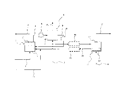
Fig. 1 is a schematic flow scheme of the system according to one
embodiment of the invention.
Fig. 2 is a schematic flow scheme of the system according to one
embodiment of the invention.
Fig. 3 is a schematic flow scheme of the system according to one
embodiment of the invention.
Fig. 4 is a schematic flow scheme of the system according to one
embodiment of the invention.
It is understood that the detailed description below is intended to improve
the
understanding of the invention, and should not be interpreted as limiting the
scope of the invention.
Description of preferred embodiments
Reactions taking place in embodiments:
The calcium oxide of the sorbent material may react with CO2 under formation
of calcium carbonate. When calcium oxide, CaO, and CO2 is brought in
contact, calcium carbonate, CaCO3 may be formed according to carbonation
reaction 1 (R1) under release of energy as heat. In the system of
embodiments of the invention, R1 may take place, for example, in the first
reactor, such as in the carbonator reactor.
R1:
CaO(s) + CO2 (g) CaCO3(s) with AHr, 298 K= - 170 kJ/mol.
CA 02829610 2013-10-09
8
In the first reactor, R1 results in lowering of the CO2 concentration in the
process gas, such as flue gas, thus resulting in a gas effluent from the first
reactor having a considerable lower concentration of CO2 than the inlet
concentration. In the case with flue gas, the concentration of CO2 before
capturing or reaction according to reaction (1), may be for example 15%.
Reaction 1 may take place, for example, at or below 650 C, and at pressures
of approximately 1 atmosphere, which may exist in the first reactor.
In addition to reacting with CO2, CaO may react with sulfur dioxide, or SO2,
under formation of calcium sulfate and energy in the form of heat, according
to reaction 2 (R2), for example if SO2 is present in the process gas.
R2:
CaO(s) + s02(g) + 1/2 02(9) __ CaSO4(s) with AHr, 298 K= -520 kJ/mol.
R2 may, for example, take place in the calciner reactor. Particularly if in-
situ
oxyfired coal combustion takes place in the second reactor R2 may take
place in the calciner reactor.
In addition SO2 may react with CaCO3 under formation of calcium sulfate and
energy in the form of heat, according to reaction 3 (R3).
R3:
CaCO3(s) + S02(g) + 1/2 02(g) = --"'" CaSO4(s) + CO2(9)
with Hr, 298 K= - 324 kJ/mol.
R3 may, for example, take place in the calciner reactor where partial
pressures of CO2 are expected.
CaO may react with water in a hydration reaction taking place in the third
reactor, such as a hydrator reactor, according to reaction 4 (R4).
R4:
CaO(s) + H20(g) - __ Ca(OH)2(s) with AHr, 298 K= - 109 kJ/mol.
CA 02829610 2013-10-09
9
,
The reversed R4 describes dehydration of Ca(OH)2, an endothermic reaction.
Dehydration may efficiently be performed, for example, at conditions of
atmospheric pressure, at a partial pressure of water at 0.1 atm, and at
temperatures above approximately 400 C, such as above 410 C. Thus,
dehydration may take place in the first reactor, such as the carbonator
reactor, and/or in pipings and/or solids separation devices, such as for
example cyclones, of the system comprising hot flue gas downstream the first
reactor.
Reactions with sulphur dioxide, for example as described by R2 and
R3, have a negative effect on the capacity of the sorbent material for
capturing CO2. Reactions according to R2 and R3, may occur if sulphur
dioxide is present in the process gas, for example in the case of the process
gas being flue gas for example resulting from burning of fuels such as coal,
or
other sulphur containing fuels. CaSO4 may result in blockage of pores in the
sorbent material, thus reducing the efficiency of CO2 capturing by the sorbent
material, for example due to blocking of the CaO present in the core of the
sorbent particles. Further, a layer of CaCO3 formed on the sorbent material
particles reduces the efficiency of the sorbent material in capturing 002.
Sintering of sorbent material which may occur also reduces the efficiency of
the sorbent material in capturing CO2. Since H20 is a small molecule it is
capable of penetrating product layers of CaSO4 and/or CaCO3 forming
Ca(OH)2 in less accessible regions of the particle. The molar volume of
Ca(OH)2 is larger than the molar volume for CaO. Thus, particles comprising
CaO may swell when hydrated according to R4, resulting in crack formations
in any present layer of CaSO4 and/or CaCO3, thus hydration according to R4
may improve the efficiency of the sorbent material and regenerate the sorbent
material. Thus, the system according to embodiments are efficient for
capturing of CO2 from process gas such as flue gas, which may contain
sulphur.
The third reactor, such as for example a hydrator reactor, arranged to
hydrate solid material received from the first reactor and recycle hydrated
solid material to the first reactor is an efficient way of increasing surface
area
of the sorbent material.
With reference to figure 1, a system for capturing CO2 from flue gas
which may or may not comprise sulfur, is described. The system comprises a
carbonator arrangement 1, receiving flue gas via piping 2. The
carbonator arrangement 1 comprises a circulating fluidized bed carbonator
CA 02829610 2013-10-09
reactor 1' optionally with internal heat transfer area in addition to solids
separation device 1" removing solids from the gas stream before the gas
stream leaves the system through piping 3. The circulating fluidized bed
carbonator reactor 1' contains particulate sorbent material, in this
particular
5 example the sorbent material essentially consists of CaO. The sorbent reacts
with CO2 and CO2 depleted flue gas leaves the carbonator reaction system 1
via piping 3, having undergone bulk solids removal.
Reacted sorbent is regenerated by decarbonation in the calciner
arrangement 11 forwarded from the carbonator arrangement 1 by piping 90,
10 which regeneration process can be described by endothermic reversed Al.
The calciner arrangement 11 comprises a circulating fluidized bed calciner
reactor 11' with solids separation device 11" removing solids in the gas
stream before the gas stream leaves the system via piping 12. Thus, in the
calciner arrangement 11, CaCO3 is converted to Ca0 and CO2, and CO2 exits
the calciner arrangement 11 by means of piping 12, having undergone bulk
solids removal. Means for energy input into the calciner arrangement 11 is
indicated by piping 13, which forwards for example a carbon source, such as
coal, and an oxygen stream, such as oxygen diluted with CO2. Sorbent,
predominantly in the form of CaO particles exits the calciner arrangement 11
by means of piping 14 and is recycled to the carbonator arrangement 1.
Optionally, a heat exchanger 15 is used to reduce the temperature of sorbent
being recycled back to the first reactor. Optionally, a heat exchanger 95 is
used to heat sorbent before entering the calciner arrangement 11. As an
additional option these two heat exchangers may be combined so that heat is
transferred from heat exchanger 15 to heat exchanger 95. Sorbent make-up
flow, for example in the form of limestone, may be added through piping 75 to
the stream of sorbent being recycled back to the carbonator arrangement 1
from the calciner arrangement 11.
The sorbent may be detonated by sulfatization if sulfur is present in the
flue gas, for example if the flue gas is resulting from burning of coal, as
described by R2 and R3, and/or by sintering, for example during calcination.
Sorbent particles, comprising CaCO3, CaO, and possible CaSO4, leave the
carbonator arrangement 1 via piping 4 and enter hydrator reactor 5. The
hydrator reactor 5 is equipped with heat transfer surface so that heat
released
during the hydration reaction can be removed from the hydrator reactor 5.
Optionally, the sorbent particles may in addition or alternatively be cooled
before entering the hydrator reactor 5, such as by means of optional heat
CA 02829610 2013-10-09
11
exchanger 6. Reactivation medium comprising gaseous H20 is fed to the
hydrator reactor 5 via piping 7. Inside the hydrator reactor the sorbent is
reacting according to R4 such that CaO is transferred to Ca(OH)2. Under this
reaction sorbent particles are regenerated. Possible excess gas, such as
steam may leave the hydrator reactor by means of piping 8 or may be
returned to carbonator arrangement 1. Regenerated sorbent particles are
transferred back to the carbonator arrangement 1 via piping 9. Optionally,
hydrated sorbent particles will be heated and dehydrated before entering the
carbonator arrangement 1, such as by means of optional heat exchanger 10.
It will be understood that in addition to any heat exchangers discussed,
heat may be removed from for example the carbonator arrangement 1 and
the hydrator reactor 5 by suitable means.
With reference to figure 2, a system is illustrated which in addition to
what is described with reference to the system of figure 1, discloses means
for pelletizing fine sorbent particles into a size suitable for the system.
Particulate sorbent hydration may act, in conjunction with a number of
particle
size reduction mechanisms, to reduce the average particle size of the
circulating particulate sorbent material by producing fine material what is
hereafter referred to as fines. Re-processing of fine material or fines into
larger particles decouples sorbent fines losses from process make-up
requirements increasing sorbent utilization and reducing operational costs.
The fines may be agglomerated to particles of a suitable size by means of the
pelletizer 19. CO2 depleted flue gas leaves the carbonator arrangement 1
through piping 3 containing a residue of particulate sorbent material, having
undergone solids separation, and enters a sorting device 16 such as for
example an electrostatic precipitator or bag filter, which removes most of the
residual solids particulate material, such as fine sorbent particles, or
fines,
from the CO2 depleted flue gas. Flue gas leaves the sorting device 16 by
means of piping 17, while the particles leaves the sorting device 16 through
piping 18, and enters the pelletizer 19. In addition, fines may be fed to the
pelletizer 19 from the calciner arrangement 11 and separator 93, particularly
for example in the case where ash free or indirect heating method is used to
bring heat into the calciner arrangement 11. In the pelletizer 19 the fines
are
mixed with a liquid such as water or a mixture of water and binding agent fed
from piping 91, resulting in wet agglomerates of the fine sorbent particles.
Thus, agglomeration takes place inside the pelletizer 19. The agglomerates
leave the pelletizer 19 by means of piping 20. The agglomerates may either
CA 02829610 2013-10-09
12
be forwarded to the hydrator reactor 5, or to the carbonator arrangement 1.
Since the hydration reaction in hydrator reactor 5 takes place at a higher
temperature and requires water, the agglomerates may be forwarded and
introduced into the hydrator reactor 5 where any water from the agglomerates
will provide water for the hydration reaction. Thus, fine sorbent particles
may
be converted to larger sorbent particles. In addition to agglomeration taking
place inside the pelletizer 19, or agglomerator, hydration may take place in
the pelletizer 19. Thus, pelletizer 19 may function as a hydrator. It is
realized
that the pelletizer may be positioned elsewhere in a system than what is
described in figure 3, and that pelletizer 19 in addition to receiving fines
from
separators 16 and 93, may receive fines from other suitable sources. The
embodiment with reference to figure 2 may also comprise a calciner
arrangement 11 as previously described from which calciner arrangement 11
CO2 rich gas is discharged via residual dust separator 93 and piping 94.
With reference to figure 3, a carbonator reactor and pelletization
system according to one embodiment is illustrated. The system illustrated in
figure 3 comprises a plurality of gas-solids separators 22, 23, 24 which act
in
separating solids from gas and further act in heating solids while cooling
gas,
thus resulting in particles with a temperature suitable for the system while
cooling the flue gas that is leaving the system, thus minimising energy input
or heat transfer surface requirements. The separators 22, 23, 24 may, for
example, be of cyclon type, or any other solids separator suitable for the
purpose. Flue gas enters the carbonator reactor 1 through piping 2 where it
optionally may be heated via heat exchanger 50. The carbonator reactor may
be comprised of one or more sections in which the particulate sorbent
material is contacted with CO2 rich flue gas and may contain heat transfer
surface to remove the heat released through reaction. A mixture of CO2
depleted flue gas and sorbent particles leaves the carbonator reactor 1 at a
temperature Ti through piping 3 and is forwarded to a point 25 where the gas
and the sorbent particles are combined with a flow of sorbent particles from
separator 23 at a lower temperature T2 and the combined flow is forwarded to
separator 22. By means of separator 22, sorbent particles are separated from
the gas and fines, which gas and fines are leaving the separator 22 via
piping 26. Larger sorbent particles, having a temperature T3 between Ti and
T2, are leaving the separator 22 and at least a part of the larger particles
are
forwarded to the hydrator reactor 5 in which hydration takes place as
described above while at least a part of the sorbent particles are recycled
CA 02829610 2013-10-09
13
back to the carbonator reactor 1. The gas and fines from separator 22, having
a temperature T3 being between Ti and T2 are forwarded to a point 27
where they are combined with a flow of sorbent particles from separator 24
and with hydrated sorbent particles from the hydrator reactor 5, having
temperatures T4 and T5 respectively both preferably lower than T3 before the
combined flow is forwarded to separator 23 via pipe 28. It is realised that
the
flows may not be combined in the same point 27, but that one of the flows
may enter downstream of the other flow, or vice versa. From the
separator 23, sorbent particles are forwarded through piping 29 to point 25,
as previously described at temperature T2, between T3 and T4 or T5, while
gas and fines, at temperature T2, are forwarded through piping 85 to a
connection point 30 where the fines and the gas is combined with a make-up
flow comprising sorbent material from piping 86. A heat exchanger 51 may be
positioned downstream separation device 23 to cool the flue gas stream
before it is mixed with the cool sorbent make-up stream, the heat removed
from heat exchanger 51 may optionally be coupled to the heating of flue gas
in heat exchanger 50 so that heat flows from heat exchanger 51 to heat
exchanger 50.The flow is forwarded to separator 24, from which sorbent
particles, at temperature T4 lower than T2, are forwarded to point 27, as
previously described while fines and gas are forwarded through piping 31,
and leaving the system, for example towards a chimney (not illustrated).
Before leaving the system, the gas and fines are optionally cooled in heat
exchanger 52 before entering separator 32, separating the gas from fines,
and forwarding fines to pelletizer 19. The pelletizer is fed liquid for
agglomeration of the fines, such as water or water and binding agent through
piping 33. In addition, the pelletizer 19 may be fed with fines from the
calciner
reactor 11, (not illustrated) through piping 34 if the the operational mode
restricts ash content from being too high. Agglomerated fines from the
pelletizer are forwarded to hydrator reactor 5, wherein the agglomerated fines
are transformed into dry sorbent particles under release of free water. The
hydrator reactor 5 is fed liquid comprising water through piping 7. Piping 90
feed sorbent material from the carbonator reactor 1 towards the calciner
system 11 (not illustrated) and piping 14 from the calciner reaction system 11
to carbonator reactor 1.
The system described above with reference to figure 3, thus describes
efficient transformation of heat from flue gas to sorbent particles, such that
flue gas is cooled and sorbent particles are heated to a suitable temperature
CA 02829610 2013-10-09
14
. ,
before the partciles enters the carbonator reactor 1. The embodiment is
suitable for systems utilizing primarily steam hydration at higher
temperatures, such as a hydration temperature about 510 C or less. For
example, such a system and for hydrating around 20% of the sorbent stream,
the following temperatures may, for example, apply: Ti being around 650 C,
T2 being between 350 and 550 C, T3 being between 540 and 610 C, T4
being between 200 and 300 C and T5 being between 300 and 510 C.
With reference to figure 4, an embodiment of the invention is
illustrated. The embodiment only differs from the embodiment discussed with
reference to figure 3 in that the stream of sorbent material from separator 23
is forwarded by means of piping directly into carbonator reactor 1 as an
additional solids feed with the purpose of direct cooling and to improve the
solids distribution and equilibrium driving forces in the upper section of the
carbonation reactor. Thus, according to the embodiment illustrated by
figure 4, the flow of sorbent material from separator 23 is not combined with
a
flow of gas and sorbent material from carbonator reactor 1 before entering the
carbonator reactor 1. It is realised that the temperature of the sorbent
material
which is forwarded to the hydrator reactor 5 from separator 22 has a
temperature essentially identical to the temperature of the sorbent material
leaving the carbonator reactor 1 through pipings 3, for example around
650 C.
With regard to the embodiments, conditions for reactions R1 and R4,
including for example temperatures and pressures, may be selected and/or
maintained to favour desired reactants and/or products. Further the conditions
may be selected to be suitable for the treated gas, the reactors and the
system. Equilibrium pressures for gaseous reactants at different temperatures
may be considered for selecting suitable conditions. For example, and with
reference to R1, the fraction of CO2 in flue gas may, for example, vary
between 10 and 15 percent by volume for flue gas from power production and
be as high as 30 percent by volume of CO2 for flue gas from a conventional
cement plant. For operating pressures of around 1 atm in the carbonator
reactor, the temperature may be selected to be suitable for removal of 90% of
the CO2. For the case of power production, 650 C is acceptable in order to
reduce the concentration of CO2 in the treated flue gas to 1 percent by
volume. For example for the case of cement plants flue gas, increased
temperatures would still allow a similar removal efficiency. Since diffusions
processes proceed at an increased rate with increasing temperature, a
CA 02829610 2013-10-09
staged temperature profile in the carbonation reactor may also be an
advantage. According to one embodiment, the temperature of an upper
section of the carbonator reactor may be below 650 C and a lower section of
the carbonator reactor above 650 C. It is realised that in analogy with the
5 discussions above regarding suitable temperatures and pressures of the
carbonator reactor, suitable conditions, such as for example temperatures
and pressures, for other parts of the system, such as for example the calciner
reactor and/or the hydrator reactor, or other parts, may be selected.
For example, CO2 depleted flue gas having 10 percent by volume of
10 water could be used to dehydrate sorbent around or slightly above 410 C.
According to one embodiment the dehydration takes place above 410 C.
The position of the hydrator reactor 5 downstream of the carbonator
reactor 1 according to the embodiments, such that sorbent material is
forwarded to the hydrator reactor from the carbonator reactor without passing
15 through the calciner reactor, results in efficient operating conditions
for the
hydrator reactor reducing the amount of cooling required for the material
entering the hydrator reactor. For example, the temperature of the hydrator
reactor may be maintained at or below 510 C, and the partial pressure of
water may be selected at or below 1 atm.
Herein before it has been described that the carbonator reactor and the
calcinator reactor are fluidized bed type of reactors, it is also appreciated
that
other types of carbonator reactors and calcinator reactors can be used.
To summarize, the present disclosure relates to a system for capturing
CO2 from a process gas. The system comprises a first reactor arranged to
receive a stream of process gas and a particulate sorbent material comprising
calcium oxide able to capture the CO2 present in the process gas such that
calcium carbonate is formed, the first reactor comprising means for
discharging CO2 depleted process gas, a first portion of particulate sorbent
material having captured CO2, and a second portion of particulate sorbent
material having captured CO2, a second reactor arranged to receive the first
portion of particulate sorbent material from the first reactor, the second
reactor comprising heating means arranged to cause release of CO2 from the
particulate sorbent material by decarbonation of the calcium carbonate to
form calcium oxide, the second reactor further comprising means for returning
the first portion of particulate sorbent material to the first reactor and
means
for discharging a CO2 rich gas stream, and a third reactor arranged to receive
the second portion of particulate sorbent material from the first reactor, the
CA 02829610 2013-10-09
16
third reactor comprising means for supplying water to the second portion of
particulate sorbent material to hydrate the calcium oxide to form calcium
hydroxide, the third reactor further comprising means for returning the second
portion of particulate sorbent material to the first reactor.
While the invention has been described and illustrated with reference to
various exemplary embodiments, it will be understood by those skilled in the
art that various changes may be made and equivalents may be substituted for
elements thereof without departing from the scope of the invention. In
addition, many modifications may be made to adapt a particular situation or
material to the teachings of the invention without departing from the
essential
scope thereof. Therefore, it is intended that the invention not be limited to
the
particular embodiment described and illustrated herein as being the best
mode contemplated for carrying out this invention, but that the invention will
include all embodiments falling within the scope of the appended claims.
Moreover, the use of the terms first, second, etc. are not intended to denote
any order or importance, but rather the terms first, second, etc. are employed
herein simply as a means of distinguishing one element from another.