Note: Descriptions are shown in the official language in which they were submitted.
CA 02829619 2013-09-10
WO 2012/129682
PCT/CA2012/050116
A MOLD STACK FOR A PREFORM
FIELD OF THE INVENTION
The present invention generally relates to, but is not limited to, a molding
system, and more
specifically the present invention relates to, but is not limited to, a mold
stack for a preform.
BACKGROUND OF THE INVENTION
Molding is a process by virtue of which a molded article can be formed from
molding material by
using a molding system. Various molded articles can be formed by using the
molding process, such
as an injection molding process. One example of a molded article that can be
formed, for example,
from polyethylene terephthalate (PET) material is a preform that is capable of
being subsequently
blown into a beverage container, such as, a bottle and the like.
As an illustration, injection molding of molding material (such as, PET, for
example) involves
heating the PET material (or other suitable molding material for that matter)
to a homogeneous
molten state and injecting, under pressure, the so-melted PET material into a
molding cavity
defined, at least in part, by a female cavity piece and a male core piece
mounted respectively on a
cavity plate and a core plate of a mold. The cavity plate and the core plate
are urged together and are
held together by clamp force, the clamp force being sufficient to keep the
cavity and the core pieces
together against the pressure of the injected PET material.
The molding cavity has a shape that substantially corresponds to a final cold-
state shape of the
molded article to be molded. The so-injected PET material is then cooled to a
temperature sufficient
to enable ejection of the so-formed molded article from the molding cavity.
When cooled, the
molded article shrinks inside of the molding cavity and, as such, when the
cavity and core plates are
urged apart, the molded article tends to remain associated with the core
piece. Accordingly, by
urging the core plate away from the cavity plate, the molded article can be
subsequently fully
demolded by ejecting it off the core piece. Ejection structures are known to
assist in removing the
molded articles from the core halves. Examples of the ejection structures
include stripper plates,
stripper rings and neck rings, ejector pins, etc.
CA 02829619 2013-09-10
WO 2012/129682
PCT/CA2012/050116
When dealing with molding a preform that is capable of being subsequently
blown into a beverage
container, one consideration that needs to be addressed is forming a so-called
"neck region".
Typically and as an example, the neck region includes (i) threads (or other
suitable structure) for
accepting and retaining a closure assembly (ex. a bottle cap), and (ii) an
anti-pilferage assembly to
cooperate, for example, with the closure assembly to indicate whether the end
product (i.e. the
beverage container that has been filled with a beverage and shipped to a
store) has been tampered
with in any way. The neck region may comprise other additional elements used
for various
purposes, for example, to cooperate with parts of the molding system (ex. a
support ledge, etc.). As
is appreciated in the art, the neck region can not be easily formed by using
the cavity and core
halves. Traditionally, split mold inserts (sometimes referred to by those
skilled in the art as "neck
rings") have been used to form the neck region.
With reference to Figure 1, a section along a portion of an injection mold 50
illustrates a typical
molding stack assembly 52 that can be arranged (in use) within a molding
machine (not depicted).
The description of Figure 1 that will be presented herein below will be
greatly simplified, as it is
expected that one skilled in the art will appreciate configuration of other
components of the injection
mold 50 that will not be discussed in the following description.
The molding stack assembly 52 includes a split mold insert pair 54 that
together with a mold cavity
insert 56, a gate insert 58 and a core insert 60, defines a molding cavity 62.
Molding material can be
injected into the molding cavity 62 from a source of molding material (not
depicted) via a receptacle
(not separately numbered) in the gate insert 58 to form a molded article,
which in this example
would be a preform suitable for subsequent blow-molding into a final-shaped
container.
In order to facilitate forming of the neck region of the molded article and
subsequent removal of the
molded article therefrom, the split mold insert pair 54 comprises a pair of
complementary split mold
inserts (not separately numbered) that are mounted on adjacent slides of a
slide pair (not depicted).
The slide pair is slidably mounted on a top surface of a stripper plate (not
depicted). As commonly
known, and as, for example, generally described in United States patent
6,799,962 to Mai et al
(granted on October 5, 2004), the stripper plate (not depicted) is configured
to be movable relative
to the cavity insert 56 and the core insert 60, when the mold is arranged in
an open configuration,
whereby the slide pair, and the complementary split mold inserts mounted
thereon, can be laterally
2
CA 02829619 2013-09-10
WO 2012/129682
PCT/CA2012/050116
driven, via a cam arrangement (not shown) or any other suitable known means,
for the release of the
molded article from the molding cavity 62.
Several types of the split mold insert pair 54 are known in the art. For
example, the split mold insert
pair 54 can be of a cavity-lock type or a core-lock type (depicted in Figure
1), depending on an
arrangement that is used for locking the split mold insert pair 54, in use,
relative to the mold cavity
insert 56 and the core insert 60. The split mold insert pair 54 can also
define a portion of the neck
region (as is the case in Figure 1) or the whole of the neck region or, put
another way, "encapsulate"
the neck region. One of the functions performed by the split mold insert pair
54 is to assist in
ejecting the molded article off the core insert 60 by "sliding" the molded
article off the core insert
60.
An example of the latter is disclosed in a co-owned US patent No. 6,989, 124
issued on January 24,
2006 to Miller et al., which teaches an injection molding method and apparatus
for ejecting a
molded plastic article from a mold. A lifting structure and/or step is
provided with a lifting portion
which is configured to contact substantially one half of an end of the molded
plastic article along a
line substantially perpendicular to the lifting direction. Since the molded
plastic article is lifted by its
end, the article does not have to be solidified at its interior, thus allowing
earlier removal of the
article from the mold, reducing cycle time. A tapered surface forms an acute
angle with respect to
the lifting portion to form a tight seal with the mold, preventing leakage.
Preferably, the neck ring
engages only an outer circumferential portion of the molded plastic article
during a majority of a
mold opening stroke.
Co-owned US patent No. 7,128,865 issued to Martin on October 31st, 2006
discloses an injection
molding method and apparatus for ejecting a molded plastic preform from a
mold. A first lifting
structure and/or step is configured to have an inner surface with an area for
sealing and aligning with
a complementary surface on a core, and to have an upper surface with an area
for sealing and
aligning with a complementary surface on a second lifting structure, said
upper surface of said first
lifting structure being configured to lift a molded plastic preform from the
injection mold in a lifting
direction for a first period of time, the lower portion of the molded plastic
preform lying in a plane
substantially perpendicular to the lifting direction. A second lifting
structure and/or step is
configured to have an inner surface configured to lift an outer surface of the
molded plastic preform
from the injection mold in the lifting direction for a second period of time,
the outer surface of the
3
CA 02829619 2013-09-10
WO 2012/129682
PCT/CA2012/050116
molded plastic preform including structure lying in a plane substantially
parallel with the lifting
direction. Since the molded plastic preform is lifted by its end, the preform
does not have to be
solidified at its interior, thus allowing earlier removal of the preform from
the mold, reducing cycle
time.
It is noted that in the illustrated example of Figure 1, a first split line 80
is formed where the split
mold insert pair 54 mates the mold cavity insert 56 and a second split line 82
is formed where the
split mold insert pair 54 mates the core insert 60. It can be said that the
first split line 80 is formed in
the transition region of the preform and the second split line 82 is formed in
the upper-thread region
of the preform.
US patent 5,158,736 discloses a cavity stripper, which is positioned between
two mold plates of a
mold is used to remove a molded U-shaped article from a cup in one of the mold
plates. The cavity
stripper is movably attached to the mold plate that houses the cup. The cavity
stripper is spring
loaded such that it follows the moving mold plate for a short distance and by
mechanical
interference urges the molded article to remain with the mandrel during
opening operations.
SUMMARY OF THE INVENTION
According to a first broad aspect of the present invention, there is provided
a molding stack
assembly for producing a molded article, the molded article including a neck
finish which includes a
support ledge, the molded article suitable for subsequent blow-molding into a
final shaped container.
The molding stack assembly comprises a core insert, a lock ring, a split mold
insert, a cavity flange
and a cavity insert for jointly defining, in use, a molding cavity for forming
the molded article, the
split mold insert and the cavity flange defining a split line therebetween,
the split line being defined
substantially along a portion of the support ledge; a biasing member disposed,
in use, between the
cavity flange and the cavity insert, the biasing member being configured to:
(a) under applied clamp
force, to allow the cavity flange to abut the cavity insert; and (b) during
initial stages of the mold
operation to bias the cavity flange away from the cavity insert.
According to a second broad aspect of the present invention, there is
provided, in a molding stack
assembly for producing a molded article, the molded article including a neck
finish which includes a
support ledge, the molded article suitable for subsequent blow-molding into a
final shaped container,
4
CA 02829619 2013-09-10
WO 2012/129682
PCT/CA2012/050116
a core insert, a lock ring, a split mold insert, a cavity flange and a cavity
insert for jointly defining,
in use, a molding cavity for forming the molded article, the split mold insert
and the cavity flange
defining a split line therebetween, the split line being defined substantially
along a portion of the
support ledge, an improvement that comprises a biasing member disposed, in
use, between the
cavity flange and the cavity insert, the biasing member being configured to:
(a) under applied clamp
force, to allow the cavity flange to abut the cavity insert; and (b) during
initial stages of the mold
operation to bias the cavity flange away from the cavity insert.
These and other aspects and features of non-limiting embodiments of the
present invention will now
become apparent to those skilled in the art upon review of the following
description of specific non-
limiting embodiments of the invention in conjunction with the accompanying
drawings.
DESCRIPTION OF THE DRAWINGS
A better understanding of the non-limiting embodiments of the present
invention (including
alternatives and/or variations thereof) may be obtained with reference to the
detailed description of
the non-limiting embodiments along with the following drawings, in which:
Figure 1 is a cross-section view of a portion of an injection mold that
incorporates a typical molding
stack assembly 52, implemented in accordance with known techniques.
Figure 2 depicts cross-section view of a portion of a molding stack assembly
implemented in
accordance with a non-limiting embodiment of the present invention.
Figure 3 depicts a perspective view of an implementation of a biasing member
of the molding stack
assembly of Figure 1.
Figure 4 depicts a cross section through a portion of the molding stack
assembly of Figure 2.
Figure 5 depicts a perspective cross-sectional view of a portion of the
molding stack assembly of
Figure 2.
5
CA 02829619 2013-09-10
WO 2012/129682
PCT/CA2012/050116
DETAILED DESCRIPTION OF EMBODIMENTS
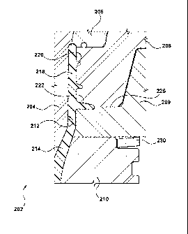
Figure 2 depicts a portion of a molding stack assembly 202 implemented in
accordance with a non-
limiting embodiment of the present invention. The molding stack assembly 202
comprises a core
insert 204, which can be implemented substantially in accordance with known
techniques, as was
described above with reference to Figure 1. The molding stack assembly 202
further comprises a
lock ring 206. Even though not described with reference to the molding stack
assembly 52 described
above with reference to Figure 1, implementation of the lock ring 206 is known
in the art and, as
such, will not be described here at much length.
The molding stack assembly 202 further comprises a split mold insert 208, a
cavity flange 209 and a
cavity insert 210. As can be clearly appreciated from the illustration of
Figure 2, the core insert 204,
the lock ring 206, the split mold insert 208, the cavity flange 209 and the
cavity insert 210 jointly
define a molding cavity 212 for forming therein, in use, a molded article 214,
which in this cases is
implemented as preform suitable for subsequent blow-molding into a final
shaped container, such as
a beverage bottle and the like.
It is noted that the split mold insert 208 is configured to define, in use,
various aspects of a neck
finish 218 of the molded article 214, and more specifically, a thread portion
220 and a portion of a
support ledge 222. It is noted that a second portion of the support ledge 222
is formed by the cavity
flange 209. In other words, it can be said that a split line 226 is defined
between the split mold insert
208 and the cavity flange 209 and, more specifically, the split line 226 is
defined substantially along
a portion of the support ledge 222.
According to embodiments of the present invention, there is also provided a
biasing member 230.
The biasing member is disposed between the cavity insert 210 and the cavity
flange 209. Generally
speaking, the biasing member 230 is configured to (a) allow the cavity flange
209 to abut (via the
biasing member 230, so to speak) the cavity insert 210 under applied clamp
force and (b) during
initial stages of the mold operation to bias the cavity flange 209 away from
the cavity insert 210.
In a specific embodiment of the present invention, the biasing member 230 can
be implemented as a
wave spring 302 depicted in a perspective view in Figure 3. An example
implementation of the
6
CA 02829619 2013-09-10
WO 2012/129682
PCT/CA2012/050116
wave spring 302 can be embodied in an off-the-shelve wave spring 302 available
form Smalley
Steel Ring Company of 555 Oakwood Road, Lake Zurich, IL 60047, USA. In other
embodiments of
the present invention, the biasing member 203 can be implemented as a disk
spring and the like. In
some embodiments of the present invention, the biasing member 230 can be made
of stainless steel.
In other embodiments of the present invention, the biasing member 230 can be
made of carbon steel.
Other implementations are, of course, possible too.
Returning to the description of Figure 2 and with further reference to Figure
4 and Figure 5, in
which Figure 4 depicts a cross section through a portion of the molding stack
assembly 202 and
Figure 5 depicts a perspective cross-sectional view of a portion of the
molding stack assembly 202;
the molding stack assembly 202 being implemented in accordance with non-
limiting embodiments
of the present invention.
It is noted that the cavity flange 209 is mounted onto a cavity plate (not
depicted), the cavity plate
housing the cavity insert 210. Within embodiments of the present invention,
the cavity flange 209 is
coupled to the cavity plate (not depicted) in a floating arrangement. In the
depicted embodiments,
the cavity flange 209 is mounted onto the cavity plate (not depicted) by means
of a bolt 402. An
outside diameter 406 of the bolt 402 and an inside diameter of a bore 404 in
the cavity flange 209
are selected such as to limit the amount of float of the cavity flange 209 in
a lateral direction, i.e.
left-right direction as viewed in Figure 4, for example.
A lower outside diameter 408 of the bolt 402 and a corresponding inner
diameter of a bore in the
cavity plate (both not depicted) are selected such as to position the bolt 402
and, therefore, the cavity
flange 209 relative to the cavity plate (not depicted) and, therefore,
relative to the cavity insert 210.
A lower bottom landing 410 of the bolt 402 bottoms out in the bore of the
cavity plate (both not
depicted) to accurately control the stroke at all four corners thereof in
other words, the lower bottom
landing 410, in a sense, acts as a stroke de-limiter, as will be explained in
greater detail herein
below.
It should be noted that the shape of the bolt 402 can be varied and, as such,
it is not limited to those
embodiments depicted in Figure 4 and Figure 5. Actually, any suitable retainer
can be used to
implement embodiments of the coupling between the cavity flange 209 and the
cavity plate (not
depicted).
7
CA 02829619 2013-09-10
WO 2012/129682
PCT/CA2012/050116
As is best seen in Figure 5, for example, the split mold insert 208 is also
provided with an aperture
502 for mounting the split mold insert 208.
Having described the architecture of the molding stack assembly 202
implemented in accordance
with non-limiting embodiments of the present invention, an operation of same
will now be described
in greater detail.
During a mold-close operation, under applied clamp force, the split mold
insert 208 is urged towards
the cavity flange 209 and the cavity insert 210, effectively compressing the
biasing member 230.
During the initial phase of a mold-open operation, the biasing member 230
urges the cavity flange
209 away from the cavity insert 210. This, in turn, means that the cavity
flange 209 follows the split
mold insert 208 away from the cavity insert 210, effectively assisting in
separating the molded
article 214 away from the molding cavity portion defined within the cavity
insert 210. It is noted
that the biasing member 230 also, in effect, pushes back on cavity insert 210
to ensure that it does
not follow with the cavity flange 209.
It is noted that a representative stroke "d" (Figure 4) of the cavity flange
209 relative to the cavity
insert 210 can be, for example, 0.5 mm. Other degrees of stroke will be
possible of course. It will be
recalled, that lower bottom landing 410 is also acting as a delimiter of the
stroke. As such, it should
be appreciated that the combination of (i) the distance between a head landing
430 of the bolt 402
and the cavity flange 209 and (ii) the lower landing 410 cooperate to delimit
the stroke "d".
A technical effect of embodiments of the present invention can include
mitigation of the stretch neck
problems of the prior art solutions, due at least in part, to the ability of
the cavity flange 209 to travel
with the split mold insert 208 during the initial phase of the mold-open
operation, which in part,
helps with urging the molded article 214 away from the cavity insert 210.
Another technical
advantage of embodiments of the present invention, may include compensation
for taper mis-
alignment due at least partially to the compensating nature of the biasing
member 230. Another
technical advantage may include improved tonnage distribution. It should be
noted that not each
every technical advantage needs to be enjoyed in each and every embodiment of
the present
invention.
8
CA 02829619 2013-09-10
WO 2012/129682 PCT/CA2012/050116
Description of the non-limiting embodiments of the present inventions provides
examples of the
present invention, and these examples do not limit the scope of the present
invention. It is to be
expressly understood that the scope of the present invention is limited by the
claims. The concepts
described above may be adapted for specific conditions and/or functions, and
may be further
extended to a variety of other applications that are within the scope of the
present invention. Having
thus described the non-limiting embodiments of the present invention, it will
be apparent that
modifications and enhancements are possible without departing from the
concepts as described.
Therefore, what is to be protected by way of letters patent are limited only
by the scope of the
following claims:
9