Note: Descriptions are shown in the official language in which they were submitted.
CA 02829919 2013-10-11
=
SUPPORT RACKING FOR SOLAR PANEL
This invention relates to support systems and support racks for solar panels
used to generate electrical power from solar radiation.
It is known to provide a racking system designed to support solar panels on a
roof or a flat surface. One such system is sold by SunLink Corporation. One
of their roof mount systems includes horizontal runners mounted on support
blocks that rest on the roof surface and vertical posts that support the solar
panels at a suitable angle to the horizontal. One problem with known systems
however is that they may be difficult to repair and maintain or that they may
not allow easy access to the underlying roof.
There is a need for an improved support racking for solar panels that will
enable the panel to be readily pivoted from an upright position (where
maintenance and repairs can be carried out) to a sloping, operating position
and then later back to the upright position, if required.
According to one embodiment of the invention, a supporting rack for a solar
panel comprises a framework adapted for mounting on a support surface, this
framework including two elongate runners that are spaced apart and parallel
to each other, and an elongate cross-member extending between and
connecting the two runners. There is also a mechanism for detachably and
adjustably mounting the solar panel on top of the framework so that the solar
panel in use extends at an acute angle to a plane defined by the two runners.
This mounting mechanism includes two front clamp assemblies, each
mountable on a respective one of the runners and clamped to a front edge of
the solar panel. Each clamp assembly includes a clamping mechanism for
clamping the front edge in a detachable manner and a pivot pin connection for
pivotally connecting the clamping mechanism to a respective one of the
runners. After installation of the supporting rack on the support surface, the
solar panel can be pivoted from the acute angle to the plane of the runners,
CA 02829919 2013-10-11
- 2 -
which is an operating position for generating electrical power from sun
radiation, to a greater angle to the plane for facilitating maintenance,
repair or
inspection of one or more of the solar panel, the support racking and the
support surface.
According to an exemplary form of this supporting rack, there is also a
respective second clamping mechanism for mounting another solar panel,
pivotally mounted on each pivot pin connection.
An exemplary version of the present clamping system enables the attached
solar panel to be tilted in the range of 00 to 35 . One version of the support
racking with its the front clamp assemblies has a locking mechanism that
keeps the solar panel upright while installers are wiring the system or
performing maintenance.
There is also disclosed herein an improved upper clamp assembly that enables
the top of the solar module to be locked in place against a back plate of the
upper clamp assembly. This clamp assembly can engage the solar panel
where it is strongest along the profile of the upper frame, thereby providing
a
strong, rigid connection.
According to a further aspect of the invention, a supporting rack for a solar
panel comprises a framework adapted for mounting on a support surface, this
framework including two elongate runners that are spaced-apart and parallel
to each other and an elongate cross-member extending between and
connecting the two runners. There is also a mounting mechanism for
detachably and adjustably mounting the solar panel on top of the framework
so that the solar panel in use extends at an acute angle to a plane defined by
the two runners. The mounting mechanism include a vertically extending,
elongate connecting mechanism extending between and connecting rear
CA 02829919 2013-10-11
=
. .
- 3 -
sections of the two runners and two rear clamp assemblies, each having a
back plate formed with a forwardly extending guideway defining a guide path.
Each rear clamp assembly also includes a 3-clamp member having a top flange
projecting towards the back plate and an integral guide pin slidably mounted
in the guideway. In addition, there is a threaded fastening device connecting
the 3-clamp member to the back plate whereby a tightening of the fastening
device pulls the 3-clamp member towards its back plate. The rear clamp
assemblies are mounted on opposite end sections of the connecting
mechanism and are arranged to clamp a top edge frame member of the solar
panel.
In an exemplary version of this supporting rack, the connecting mechanism
includes an elongate wind deflecting plate and two end plates each mounted
on a respective one of the runners and each connected to a respective bottom
corner of the wind deflecting plate.
According to another embodiment of the invention, a supporting rack for a
solar panel includes two separate elongate runners adapted for mounting on a
fixed support surface so that the runners are spaced apart from and parallel
to
each other. Each runner is formed with a longitudinal connecting channel
extending along a top of the runner. The rack further includes at least one
separate elongate frame member for connecting the two runners and two
panel clamping assemblies, each pivotably mounted on a respective one of the
two runners. Each of these assemblies includes a connecting device engagable
with sides of the respective connecting channel to secure the panel clamping
assembly to the top of its runner. In use, each connecting device can be
disengaged from the sides of its respective connecting channel to allow the
connecting device and the rest of its clamping assembly to be moved in a
lengthwise direction along their runner to a desired position for supporting
the
solar panel.
CA 02829919 2013-10-11
=
- 4 -
There is also disclosed herein an improved runner for solar racking that can
be
provided with rubber or rubber like pads which can be fastened to the bottom
of the runner to protect the roof. Also a sheet metal wire cap can be clipped
onto the side of the runner to hide wiring.
Further features and advantages of the present support racking will be
apparent from the following detailed description taken in conjunction with the
drawings.
In the drawings,
Figure 1 is a perspective view of the combination of a support racking
constructed in accordance with one embodiment of the invention and a solar
panel, this view taken from above and from a rear side;
Figure 2 is another perspective view of the combination of racking and panel
of figure 1, this view being taken from above and from the front end of the
racking;
Figure 3 is a rear view of the support racking of figure 1, this view showing
a
wind deflector;
Figure 4 is a side elevation of the combined racking and panel of figure 1;
Figure 5 is a detail view showing a ballast stone mounted on two cross
members of the racking;
Figure 6 is a detail view in perspective showing a front clamp assembly
mounted on a runner and connected to a front edge of a solar panel;
CA 02829919 2013-10-11
. .
- 5 -
Figure 7 is another detail view in perspective of the front clamp assembly,
this
view being taken from above and from the front end;
Figure 8 is a side view of a base clamp member used in the front clamp
assembly;
Figure 9 is a cross-sectional view of the base clamp assembly taken along the
line IX-IX of Figure 8;
Figure 10 is a top view of a clevis pin bracket used to connect the front
clamp
assembly to its runner;
Figure 11 is a longitudinal cross-section taken along the line XI-XI of Figure
10;
Figure 12 is a detail view in perspective illustrating how the base clamp
member of Figure 9 is mounted on a clevis pin, this view showing the
transverse profile of the clevis pin;
Figure 13 is a detail view in perspective showing how a cross-member is
connected to a flange of a runner;
Figure 14 is another detail view in perspective showing an end of a cross-
member connected to one flange of a runner;
Figure 15 is a detail view in perspective showing the end profile for a runner
and portions of flexible clips to attach cross-members;
CA 02829919 2013-10-11
. ,
- 6 -
Figure 16 is a perspective view of the solar racking and panel taken from
below and from the rear, this view showing rubber pads mounted on both the
runners and the cross-members;
Figure 17 is a detail view of one of the rubber pads showing how it is
fastened
in place;
Figure 18 is a detail view in perspective showing an end support plate
mounted on the end of a runner and connected to a corner of a wind deflector;
Figure 19 is another detail view but showing the end connecting plate from the
rear side;
Figure 20 is a perspective view showing the solar panel connected to the wind
deflector at its top by 3-clamp assemblies;
Figure 21 is a side elevation of a rear clamp assembly for connecting a top
frame of the solar panel to the wind deflector;
Figure 22 is a bottom view of the rear clamp assembly of Figure 21;
Figure 23 is a front end view of the rear clamp assembly;
Figure 24 is a perspective view of the rear clamp assembly taken from below
and from the front end;
Figure 25 is a detail view showing how the rear clamp assembly is connected
to the wind deflector, this view being taken from above;
CA 02829919 2013-10-11
. .
- 7 -
Figure 26 is another detail view of the rear clamp assembly showing the
manner in which the J-clamp is slidably connected to the back plate;
Figure 27 is a perspective view taken from above and from the front and
showing an elongate wire cap extending along one runner; and
Figure 28 is a detail elevation view showing the manner in which the wire cap
is mounted on one side of the runner.
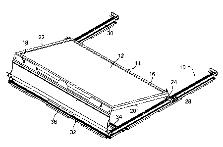
Figures 1 to 4 illustrate a support racking 10 constructed in accordance with
one embodiment of the invention. Mounted at an angle on top of the support
racking is a standard solar panel 12 having a rectangular shape. The
perimeter of the solar panel can be formed by a rectangular metal frame 14.
With the solar panel in the sloping position shown, the metal frame has a
bottom frame member 16, a top frame 18 and two parallel side frame
members 20 and 22. The solar panel with its frame is detachably mounted on
top of the racking. The mounting arrangement includes two front clamp
assemblies 24, 26. The clamp assembly 24 is shown in more detail in figures
6 and 7 and it will be understood that the clamp assembly 26 is of similar
construction.
Two major components of the support racking are two elongate, parallel
runners 28, 30 as well as two elongate parallel cross-members 32, 34.
Mounted on the cross members is at least one ballast stone 36. Although only
one ballast stone is shown, the actual number of ballast stones used and
mounted on the cross-members will depend upon weight requirements as
determined by engineering calculations. If no ballast stone is required, the
racking may include only one cross-member used to connect and properly
space the runners.
CA 02829919 2013-10-11
. ..
- 8 -
The cross sectional profile of each runner can be seen clearly from Figures 13
to 15. The runner, which can be formed from aluminum or aluminum alloy
has a central vertical web 40 and two bottom flanges 42, 44. An upper
connecting channel 46 extends along the web 40 and it can have a generally
rectangular cross section as shown in figure 8 with an elongate slot 48
through
which a threaded fastener can extend as shown in figure 6. For fastening
purposes, the bottom of the vertical web 40 splits into two parallel branches
50, 52 with the bottom flange 42 connected to branch 50 and the flange 44
connected to the branch 52. Also, formed on opposite sides of the web 40 and
just above the branches are two V grooves 54, 56 to provide means for
attaching a sheet metal wire cap as explained below. Formed at suitable
locations along each of the flanges 42, 44 are rectangular openings 60 which
accommodate special resilient and flexible clip members 62.
Each clip
member is used to detachably connect one end of a cross member 32 to its
respective runner. Each of the cross members is also formed with a
rectangular opening 64 through which the upwardly extending arms 66 of the
clip member extend. Also each clip member is formed with two generally L-
shaped connecting arms 68 on its opposite sides. The horizontal leg of each of
these arms engages the top surface of the flange 42 or 44. The bottom edges
of the two connecting arms are joined by a bottom section 70 of the clip
member and the two parallel arms 66 extend upwardly from this bottom
section 70. As will be clear from Figures 13 and 14, outwardly extending edge
flanges 72, 74 of the arms 66 engage the top surface of one of two side
flanges 76, 78 formed on opposite sides of the respective cross-member.
These two side flanges are connected to each other by an integral, elongate
central channel 80. As explained further hereinafter, the channel 46 on top of
each runner allows various mating components to be connected to the top of
the runner and allows these components to slide along the runner so that they
can be positioned to provide the correct angle for the solar panel.
CA 02829919 2013-10-11
. ,
- 9 -
Turning now to the front clamp assembly best shown in figures 6 and 7, each
clamp assembly can include two clamping devices 82, 84, one for each of the
solar panels that are being connected to opposite sides of the runner. These
two clamping devices are constructed in a similar manner and accordingly only
the clamping device 84 will be described in detail herein. The clamping device
82 is shown connected to the bottom frame member 16 of a solar panel.
Clamping device 84 is shown unattached but, in use, it would also be attached
to the bottom frame member of an adjacent solar panel. The clamping device
includes an outer clamp member 86 that is adjustably connected to a base
clamp member 88. Clamp member 86 has two parallel, spaced apart legs 90,
92 that are integrally joined by an end plate 94 that includes a projecting
end
flange 96 that can be formed with gripping teeth or ridges on its inner
surface,
that is the surface adapted to engage the bottom frame member 16 of a solar
panel. A fastener hole is formed in the end plate 94 and through this hole
extends a bolt 98 secured in place by a washer 100 and nut 102. The base
clamp member has a generally rectangular connecting section 104 having two
parallel side walls that define guiding surfaces for the aforementioned legs
90,
92. Close to but spaced apart from one side of the connecting section is an
integrally connected guide wall 106 which extends from a pivotal mounting
section 108. This mounting section has a round portion into which an end
portion of a clevis pin 235 extends. The clevis pin is supported by a clevis
pin
bracket 110 that is mounted by two threaded fasteners 112 to the top of the
runner. These threaded fasteners which can be bolts are secured in place by
their respective washers 114 and nuts 116. The rounded bracket extends
across the gap or slot formed in the top of the runner. It will be understood
that the head of each bolt 112 is either wider than the slot 48 or a washer
(not
shown) mounted next to the head is wider than the slot 48, thereby
preventing passage of the head of the bolt through the slot. By loosening the
two nuts 114, it is easy to adjust the position of the bracket and the rest of
the front clamping assembly along the top of the runner in either direction.
CA 02829919 2013-10-11
- 10 -
Thin walled cylindrical sleeves 118 can be mounted on the clevis pin in order
to correctly position the front clamping assemblies for mounting of their
respective solar panels and to prevent them from moving.
Figures 8 and 9 illustrate further details of the base clamp assembly 88. In
particular, it will be seen that the rectangular connecting section 104 is
formed
with a rectangular cavity 220 through which the bolt 98 can be passed. At one
end of the cavity is a recess 222 which snuggly accommodates the head 224
of the bolt 98. The head of the bolt is formed with a multi-sided tool
receiving
end hole 226 into which a turning tool can be inserted for turning or holding
the bolt as the nut is applied. Figure 9 also shows a generally circular
passage
230 formed in the mounting section 108. On one side of this passage is an
integral stop 232 which can be in the form of a ridge extending the length of
the passage. This stop is used to limit pivotable movement of the clamping
device on the clevis pin 235, the end of which can be seen in Figure 12.
Further details of the clevis pin bracket 110 can be seen in Figures 10 and
11.
The aforementioned threaded fasteners 112 extend through holes 236 formed
in the two flat end sections 238 of the bracket. The bracket forms an inverted
generally U-shaped channel 240 which is shaped to snuggly accommodate the
central section of the clevis pin 235. In particular, the top of the inverted
channel can be formed with an integral, inwardly extending ridge or elongate
projection 242 that can extend the length of the channel. The ridge 242 fits
snuggly in a curved, axially-extending recess 244 formed along the top of the
clevis pin (see Figure 12). The engagement between the internal ridge 242
and the sides of the recess 244 effectively prevents any rotation of the
clevis
pin relative to the bracket and the adjacent runner. The transverse profile of
the clevis pin 235 seen in Figure 12 which shows the pin formed with a central
hole 246. Extending snuggly into this hole is a connecting pin 248 which is
integrally or otherwise attached to a specially shaped end cap 120, one of
CA 02829919 2013-10-11
- 11 -
which is mounted on each end of the clevis pin. The end cap 120 is held in
place by a friction fit between the pin 248 and the side of its hole 246. The
clevis pin has a flat bottom surface 250 which rests on top of its respective
runner. In addition to the central hole 246, the clevis pin can be formed with
two additional and similar passageways 252 and 254 located on opposite sides
of the central hole and separated therefrom. The clevis pin can have a uniform
cross-section throughout its length. The curved recess 244 of the pin receives
a locking mechanism for the adjacent front clamp and the two ends of the
recess provide positive stops at the ends of a 90 degree arc through which the
recess extends. These two stops are at 90 degrees forward and 0 to 5
degrees back.
The bottom edge 122 of the end cap 120 is straight while its top edge has a
rounded central section 124 and two radially extending edges 126, 128 at
opposite ends of the central section 124. As indicated, the shape of each end
cap 120 and the clevis pin determine the degree of rotation of the respective
front clamp assembly. The curved gap recess 244 lies between the recessed
top of the the clevis pin and the mounting section 108. One or more locking
keys (not shown) can be inserted into the recess 244 in order to lock the
clamp assembly in a desired position together with the solar panel connected
thereto. The preferred front clamp assemblies allow the solar panel module to
be held in the upright position (that is 900 to the surface of the roof) and
then
tilted into its operative position (shown in figures 1 to 4). The clamping and
locking arrangement allows for easy installation and maintenance of the solar
panels as well as easy access to all fasteners. By locking the clamping
assemblies so that they hold the panel upright, the installation of necessary
wiring or the performance of maintenance is facilitated. The front clamping
assemblies of the invention also help prevent over rotation which is helpful
during the shipping and delivery of the solar racking since these clamps will
always be in the correct orientation on site. Also because the solar panels
can
CA 02829919 2013-10-11
- 12 -
readily be pivoted to the upright position by means of the front clamp
assemblies, building owners and landlords will have ready access to the roof
even after the solar panel system has been fully installed.
Figures 16 and 17 illustrate the use of rubber pads 140 and 142 mounted on
the bottom of the racking to support the racking and the solar panel on a roof
surface without damaging this surface. As shown in Figure 16, there are three
of the rubber pads 140 distributed along each of the runners 28, 30 and there
are three of the pads 142 distributed along each of the cross-members 32, 34.
The threaded fasteners 144 used to secure each of these rubber pads to its
respective runner or cross-member can be seen in Figure 17. The heads of
these fasteners fit within a central, longitudinal groove 146. Also extending
along the bottom of the groove can be an elongate V-groove 148 which helps
to center and locate the threaded fasteners. In the case of the fastener used
to attach the rubber pad to a runner, the threaded shank of the fastener can
readily be threaded into the longitudinal slot 150 formed between the two
branches 50, 52 of the runner (see Figure 15). In the case of the fasteners
for
the pads that are attached to the cross-member, the threaded shanks of these
fasteners can extend into the longitudinal slot 152 formed by the central
channel 80.
Figures 18 and 19 illustrate the construction of an end plate 160 in the form
of
an angle member which is used to connect a wind deflector 162 to the end of
each runner. The bottom or horizontal leg 164 of the end plate has a central
hole through which a single fastener 166 extends. It will be understood that
the head of this fastener or bolt 166 is slidably secured in the channel 46 in
the top of the runner. The bolt is secured in place by means of a washer 168
and nut 170 so that the end plate extends perpendicular to the length of its
respective runner. Two threaded fasteners 172 extend through two holes
formed in the vertical leg 174. Each of these fasteners is used to secure one
CA 02829919 2013-10-11
- 13 -
bottom corner of its respective wind deflector which can be secured to the
fastener by means of a nut (not shown). In the exemplary wind deflector
shown, its bottom edge is formed with a vertical slot 176 through which the
fastener 172 extends. The exemplary holes in the vertical leg 174 are six
sided as indicated at 180. The fasteners have a six sided portion adjacent the
round head which fits into the multiple-sided opening 180, thereby preventing
the threaded fastener from rotating in the opening. This arrangement
facilitates attachment of a nut onto the fastener. Because of the slot 176, it
is
simply necessary to loosen the nut and not completely remove same in order
to detach the wind deflector from the end plate.
Another inventive feature of the present solar racking is the manner in which
the top frame member 18 of the solar panel is connected to the top of the
wind deflector 162. The use of and construction of rear clamp assemblies 260
are illustrated in Figures 20 to 26. Once the solar module panel has been
clamped along its bottom edge by the two front clamp assemblies, it is rotated
back and rests on the two rear clamp assemblies. The two clamps are able to
lock the solar module in place against a back plate 194 of each rear clamp. A
tongue and groove feature of the clamp described below prevents rotation
between a 3-clamp member or connecting block 186 and the back plate 194.
The two rear clamp assemblies engage the solar panel where it is strongest
along the profile of the top frame member 18, thus providing a very rigid
connection.
Figure 21 to 24 illustrate details of each rear clamp assembly 260. The two
main components of each clamp assembly are the aforementioned back plate
194 and the 3-clamp member or connecting block 186. Formed on the back
plate is a forwardly extending guideway 262 defining a guide path 264. In an
exemplary clamp assembly 260, the guideway is formed by two separate
guide members 266, 268 which are parallel and spaced apart. Formed in each
CA 02829919 2013-10-11
. .
- 14 -
guide member is an elongate, inwardly directed groove 270 visible in Figure
26. The two grooves 270 define the guide path 264 along which the 3-clamp
member moves in a linear manner. The illustrated, exemplary 3-clamp
member 186 is adjustably connected to the back plate by means of a threaded
fastening device which includes a bolt 274 having a head 276 which fits
snuggly in a multi-sided recess 278 formed in the 3-clamp member. Threaded
onto the bolt is a flanged nut 280 shown in Figure 25. The bolt extends
through a hole formed near an upper corner of the wind deflector 162.
The illustrated 3-clamp member is formed with two similar rectangular
recesses 282 on its upper half. Also, this clamp member has a top flange 284
which extends towards the back plate and which is used to grip an edge of the
upper or top frame of the solar panel. The back plate can be secured at all
times to the wind deflector by means of a single, short bolt 290 which extends
through a washer 292. A central hole formed in the back plate is threaded to
engage and hold the threads of this bolt. Two cylindrical pins can be mounted
in the back plate on opposite sides of the bolt 290, these being indicated at
294. The round ends of these pins engage the adjacent side of the upper
frame member of the solar panel creating a firm grip.
Sheet Metal Wire Cap
An exemplary, elongate wire cap 200 can be mounted on the inner side of
each runner as shown in figure 27. The profile of the wire cap 200 can be
seen in Figure 28. The exemplary cap has a vertical, central section 202, a
horizontal bottom section 204 and a sloping top section 206. The bottom
section is integrally connected to a sloping edge flange 208 and this edge
flange sits in one of the V-grooves formed on the side of the runner.
Extending vertically upwardly from the top section 206 is a top flange 210,
the
upper edge of which can fit into a downwardly opening groove 212 of the
CA 02829919 2013-10-11
. ,
- 15 -
runner. Once the wire cap is mounted along its top and bottom edges, it can
be further secured in place by screws 214 which extend through holes formed
in the top flange 210 and in the top section of the runner. An enclosed
chamber 216 is formed between the wire cap and the runner and electrical
wires, control wires etc. can extend through the length of this chamber to and
from the solar panel.
Although the present invention has been illustrated and described as
embodied in exemplary embodiments, e.g. embodiments having particular
utility in the support of solar panels, it should be understood that the
present
invention is not limited to the details shown herein, since it will be
understood
that various omissions, modifications, substitutions and changes in the forms
and details of the disclosed racking systems and clamps and other components
and their operation may be made by those skilled in the art without departing
in any way from the scope of the present invention. For example, those of
original skill in the art will readily adapt the present disclosure for
various
other applications without departing from the scope of the present invention.
25