Note: Descriptions are shown in the official language in which they were submitted.
CA 02829965 2013-10-15
STACKABLE LOW DEPTH TRAY
BACKGROUND
Injection-molded plastic beverage crates are used to ship beverage containers,
such as
plastic bottles, to stores. Often, it is intended that consumers will view the
bottles in the store
to make their selection and then remove the desired bottles from the crate.
Many known crates includes a base, a pair of opposed end walls extending
upward
from the base, and a pair of opposed side walls extending upward from the base
between the
end walls. Each side wall includes a plurality of side columns extending
upward from the
base to a side band.
SUMMARY
The present invention relates to crates for carrying bottles, particularly
plastic
beverage bottles. One example for multi-serving (e.g. 2 liter) bottles is
disclosed. One
example for single serving (e.g. 20 oz or half-liter) bottles is disclosed.
The crates are
preferably injection molded as a single piece of plastic, such as HDPE or
other suitable
material.
The crate includes a base, a pair of opposed end walls extending upward from
the
base, and a pair of opposed side walls extending upward from the base between
the end walls.
Each side wall includes a plurality of side columns extending upward from the
base to a side
band.
Each side band includes a logo portion having a protruding portion protruding
upward
relative to an upper edge of the side band. Each side band further includes a
curved recess
formed in a lower edge of the side band, the curved recess complementary to
the protruding
portion of the logo portion. The protruding portions of the logo portions may
be offset in
opposite directions from a center of the side walls.
In the disclosed embodiments, the logo portions are ellipses having its major
axis at an
acute, non-zero angle relative to the straight upper edge of the side band.
Each ellipse is
truncated by the curved recess. Each ellipse may also be truncated by the
straight lower edge
of the side band.
1
CA 02829965 2013-10-15
The logo portions provide increased brand association with the product being
sold
from the crate. The logo portions also provide an anti-theft feature in that
the crate will not
provide a stable surface if inverted.
BRIEF DESCRIPTION OF THE DRAWINGS
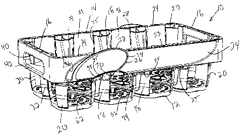
Figure 1 is a perspective view of a crate according to one embodiment of the
present
invention.
Figure 2 is a side view of the crate of Figure 1.
Figure 3 is an end view of the crate of Figure 1.
Figure 4 is a top view of the crate of Figure 1.
Figure 5 is a bottom view of the crate of Figure 1.
Figure 6 is a perspective view of the crate of Figure 1 with a plurality of
bottles
received therein.
Figure 7 is a side view of the crate of Figure 1 with an identical crate
nested therein.
Figure 8 is a perspective view of the crates of Figure 7.
Figure 9 is a perspective view of a crate according to another embodiment of
the
present invention.
Figure 10 is a side view of the crate of Figure 9.
Figure 11 is an end view of the crate of Figure 9.
Figure 12 is a top view of the crate of Figure 9.
Figure 13 is a bottom view of the crate of Figure 9.
Figure 14 is a side view of the crate of Figure 9 with an identical crate
nested therein.
Figure 15 is a perspective view of the crates of Figure 14.
DETAILED DESCRIPTION OF THE PREFERRED EMBODIMENT
A crate 10 according to one embodiment of the present invention is shown in
Figures
1-8 and is particularly suited for multi-serving bottles. The crate 10
includes a base 12
including a plurality of circular platforms each defining a bottle support
surface. A pair of
side walls 14 extend upward from side edges of the base 12. End walls 16
extend upward
from end edges of the base 12. Each side wall 14 includes a plurality of side
columns 18
2
F
CA 02829965 2013-10-15
extending upward from the base 12. Corner columns 20 extend upward from
corners of the
base, while end columns 22 extend upward from ends of the base 12.
Each side wall 14 includes a side band 24 spaced upwardly from the base 12 and
positioned along the outside of the side columns 18. The side band 24
generally includes a
straight upper edge 23 and a straight lower edge 25, but also includes a logo
portion 26, which
in this embodiment is in the form of an ellipse or oval 26 whose major axis is
at an acute, non-
zero angle relative to the straight upper edge 23. The logo portion 26 is
superimposed over
the straight upper edge 23 of the side band 24 and includes a curved
protruding portion 28 that
protrudes upward relative to the otherwise straight upper edge 23 of the side
band 24. At a
lower end, the logo portion 26 is truncated by the straight lower edge 25 and
a curved cutout
30 in the otherwise straight lower edge 25 of the side band 24. The logo
portion 26 is
completely circumscribed by a rib 34. The side band 24 further includes a
recessed arcuate
portion 36 adjacent the logo portion 26. Between the columns 18, the side wall
14 includes a
concave interior wall 31, spaced inward from the side band 24.
The logo portions 26 on the two side bands 24 are off-center and are on
opposite ends
of the centerline. This arrangement of the curved protruding portions 28
provides a relatively
unstable surface for the crate 10 if the crate 10 were flipped over. This
discourages theft of
the crate 10, because it cannot be used as a stool, step or other support
surface.
Each end wall 16 includes an upper handle portion 40 and a lower handle
portion 42
extending between the comer columns 20. The upper handle portion 40 is spaced
above the
lower handle portion 42 to provide a handle opening. The end columns 22 extend
upward
from the base 12 to the lower handle portion 42.
Each of the side columns 18 includes a lower column portion 44 and an upper
column
portion 45. The lower column portion 44 is below the side band 24. The upper
column
portion 45 is formed on the interior of the side band 24. The lower column
portion 44
includes a pair of angled, concave lower side walls joined by a front wall.
The upper column
portion 45 includes a pair of angled, concave upper side walls joined by an
upper front wall.
The upper side walls are recessed (i.e., offset outward of the crate 10)
relative to the lower
side walls. A vertical interior rib 54 extends generally perpendicularly
between the side band
24 and the upper front wall of each upper column portion 45.
3
CA 02829965 2013-10-15
A plurality of low profile dividers 62 extend upward from the base 12 between
the
circular platforms, thereby partially defining bottle receiving pockets.
Figure 2 is a side view of the crate 10. As shown, the curved protruding
portions 28 of
the side band 24 are the highest points on the crate 10.
Figure 3 is an end view of the crate 10. Figure 4 is a top view of the crate
10. Figure
5 is a bottom view of the crate 10.
Figure 6 is a perspective view of the crate 10 with a plurality of bottles 50
(in this
example, 2-liter bottles 50) received therein.
In Figure 7, the crate 10 is empty and is nested into an identical crate 10.
When
nested, the crates 10 occupy less volume for efficient storage and shipping
for reuse. The
curved protruding portion 28 of the logo portion 26 of the lower crate 10 is
received in the
curved cutout 30 in the side band 24 of the upper crate 10. In this manner,
the curved
protruding portions 28 do not increase the nested height of the crates 10.
Figure 8 is a perspective view of the nested crates 10 of Figure 7.
A crate 110 according to a second embodiment of the present invention is shown
in
Figures 9-15 and is particularly suited for single-serving bottles. The crate
110 includes a
base 112, which is generally a flat lattice of ribs. A pair of side walls 114
extend upward
from side edges of the base 112. End walls 116 extend upward from end edges of
the base
112. Each side wall 114 includes a plurality of side columns 118 extending
upward from the
base 112. Corner columns 120 extend upward from corners of the base, while end
columns
122 extend upward from ends of the base 112.
Each side wall 114 includes a side band 124 spaced upwardly from the base 112
and
positioned along the outside of the side columns 118. The side band 124
generally includes a
straight upper edge 123 and a straight lower edge 125, but also includes a
logo portion 126,
which in this embodiment is in the form of an ellipse or oval whose major axis
is at an acute,
non-zero angle relative to the straight upper edge 123. The logo portion 126
is superimposed
over the straight upper edge 123 of the side band 124 and includes a curved
protruding
portion 128 that protrudes upward relative to the otherwise straight upper
edge 123 of the side
band 124. At a lower end, the logo portion 126 is truncated by the straight
lower edge 125
and a curved cutout 130 in the otherwise straight lower edge 125 of the side
band 124. The
4
CA 02829965 2013-10-15
logo portion 126 is completely circumscribed by a rib 134. The side band 124
further
includes a recessed arcuate portion 136 adjacent the logo portion 126. Between
the columns
118, the side wall 114 includes at least one vertical rib 133 extending inward
from the side
band 124.
The logo portions 126 on the two side bands 124 are off-center and are on
opposite
ends of the centerline. This arrangement of the curved protruding portions 128
provides a
relatively unstable surface for the crate 110 if the crate 110 were flipped
over. This
discourages theft of the crate 110, because it cannot be used as a stool, step
or other support
surface.
Each end wall 116 includes an upper handle portion 140 and a lower handle
portion
142 extending between the corner columns 120. The upper handle portion 140 is
spaced
above the lower handle portion 142 to provide a handle opening. The end
columns 122
extend upward from the base 112. A center end column 122 extends upward only
to the
lower handle portion 142.
Each of the side columns 118 includes a lower column portion 144 and an upper
column portion 145. The lower column portion 144 is below the side band 124.
The upper
column portion 145 is formed on the interior of the side band 124. The lower
column portion
144 includes a pair of angled, concave lower side walls joined by a front
wall. The upper
column portion 145 includes a pair of angled, concave upper side walls joined
by an upper
front wall. The upper side walls are recessed (i.e., offset outward of the
crate 110) relative to
the lower side walls.
Figure 10 is a side view of the crate 110. As showr4, the curved protruding
portions
128 of the side band 124 are the highest points on the crate 110.
Figure 11 is an end view of the crate 110. Figure 12 is a top view of the
crate 110.
Figure 13 is a bottom view of the crate 110.
In Figure 14, the crate 110 is empty and is nested into an identical crate
110. When
nested, the crates 110 occupy less volume for efficient storage and shipping
for reuse. The
curved protruding portion 128 of the logo portion 126 of the lower crate 110
is received in the
curved cutout 130 in the side band 124 of the upper crate 110. In this manner,
the curved
protruding portions 128 do not increase the nested height of the crates 110.
5
CA 02829965 2013-10-15
Figure 15 is a perspective view of the nested crates 110 of Figure 12.
In accordance with the provisions of the patent statutes and jurisprudence,
exemplary
configurations described above are considered to represent a preferred
embodiment of the
invention. However, it should be noted that the invention can be practiced
otherwise than as
specifically illustrated and described without departing from its spirit or
scope.
6