Language selection

Search

Patent 2830127 Summary

Third-party information liability

Some of the information on this Web page has been provided by external sources. The Government of Canada is not responsible for the accuracy, reliability or currency of the information supplied by external sources. Users wishing to rely upon this information should consult directly with the source of the information. Content provided by external sources is not subject to official languages, privacy and accessibility requirements.

Claims and Abstract availability

Any discrepancies in the text and image of the Claims and Abstract are due to differing posting times. Text of the Claims and Abstract are posted:

  • At the time the application is open to public inspection;
  • At the time of issue of the patent (grant).
(12) Patent: (11) CA 2830127
(54) English Title: BRUSH ROLLER OF A FLOOR CLEANING DEVICE
(54) French Title: CYLINDRE DE BROSSE D'UN APPAREIL D'ENTRETIEN DES SOLS
Status: Granted and Issued
Bibliographic Data
(51) International Patent Classification (IPC):
  • A47L 09/04 (2006.01)
  • A46B 13/00 (2006.01)
(72) Inventors :
  • LIFFERS, ACHIM (Germany)
  • LAASER, ANDREAS (Germany)
(73) Owners :
  • STEIN & CO. GMBH
(71) Applicants :
  • STEIN & CO. GMBH (Germany)
(74) Agent: GOWLING WLG (CANADA) LLP
(74) Associate agent:
(45) Issued: 2018-11-20
(86) PCT Filing Date: 2012-10-17
(87) Open to Public Inspection: 2013-04-25
Examination requested: 2017-07-26
Availability of licence: N/A
Dedicated to the Public: N/A
(25) Language of filing: English

Patent Cooperation Treaty (PCT): Yes
(86) PCT Filing Number: PCT/DE2012/001026
(87) International Publication Number: DE2012001026
(85) National Entry: 2013-09-13

(30) Application Priority Data:
Application No. Country/Territory Date
10 2011 116 419.0 (Germany) 2011-10-18

Abstracts

English Abstract


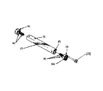
A rotating brush roller of a floor care device is a cylindrical
rotational element including a hollow body as a central piece and
end pieces to be supported via bearings in a brush housing of the
floor care device. A spiral, outwardly open, receiving shaft or
groove is provided in the outer circumferential surface of the
hollow body for receiving and retaining therein a continuous
spiral brush strip. The central piece is a self-supporting
hollow body of plastic, into opposite ends of which the end
pieces engage with a form-fitting connection. The receiving
shaft for receiving the brush strip continues at least partially
in the end pieces.


French Abstract

L'invention concerne un cylindre de brosse (A) d'un appareil d'entretien des sols équipé d'un cylindre de brosse constituant un élément rotatif cylindrique, ledit cylindre de brosse (A) se présentant comme un corps creux monté dans un carter de brosse par des pièces d'extrémité (4, 5), par l'intermédiaire de roulements. Selon l'invention, une gorge réceptrice en spirale (2) comportant une zone traversante externe pour l'insertion et la fixation d'une bande de brosse continue (3), est formée dans la région de la paroi externe du corps creux. Le cylindre de brosse comprend un segment central (1) sous forme d'un corps creux autoportant en matière plastique, dans lequel s'engagent les pièces d'extrémité (4, 5) externes formant un assemblage par complémentarité de formes, les pièces d'extrémité (4, 5) prolongeant au moins partiellement la gorge réceptrice (2).

Claims

Note: Claims are shown in the official language in which they were submitted.


Claims:
1. Brush roller of a floor care device, wherein:
the brush roller as a cylindrical rotational element
comprises a central segment and outwardly located first and
second end pieces,
the brush roller is configured and adapted to be
arranged by the end pieces via bearings in a brush housing
of the floor care device,
the brush roller as a hollow body comprises a
receiving shaft extending spirally along the central
segment with an outwardly located through passage area for
receiving and retaining a continuous brush strip, and the
receiving shaft extends along the first end piece to an
opening that is located on an end face side of the first
end piece and that communicates into the receiving shaft
for insertion and removal of the brush strip,
the central segment comprises at least 50% of the
total length of the brush roller,
the central segment is formed as a self-supporting
hollow body of plastic and comprises the receiving shaft
extending spirally along an outer circumferential surface
of the central segment,
the end pieces engage with a form-fitting connection
into the hollow body of the central segment,
the end pieces comprise shaft ends for being received
in the bearings of the floor care device,
-7-

the second end piece continues the receiving shaft for
the brush strip extending axially beyond an axial end of
the central segment,
the receiving shaft extends spirally along an entire
axial length of the central segment and the first and
second end pieces,
the second end piece has an opening of the receiving
shaft on an end face side of the second end piece, and
the brush strip can be slidingly inserted into and
removed from the receiving shaft through both the opening
on the end face side of the first end piece and the opening
on the end face side of the second end piece.
2. Brush roller according to claim 1, characterized in that
the central segment is formed as a self-supporting hollow
body by concentric pipe bodies spaced radially apart by
ribs, and the receiving shaft with its outwardly located
through passage area is arranged between the pipe bodies.
3. Brush roller according to claim 1, characterized in that
the end pieces comprise deflector elements in the area
facing away from the central segment.
-8-

4. Brush roller according to claim 1, characterized in that
the end pieces are insertable in a radial
force-transmitting and form-fitting manner into the hollow
body of the central segment via elements of elastic
material.
5. Brush roller according to claim 1, characterized in that
the end pieces at their outwardly located end face sides
comprise receiving openings and balancing weights received
therein.
6. A brush roller for a floor care device, comprising:
a cylindrical brush body that extends axially along an
axis, is made of plastic, has a hollow interior space
therein, and has a spiral groove extending spirally about
said axis in an outer circumferential surface of said brush
body;
two end pieces that are partially inserted into said
hollow interior space at two opposite axial ends of said
brush body, and each have a spiral extension groove which
extends spirally about said axis in an outer
circumferential surface of a respective one of said end
pieces and which is aligned with and continues said spiral
groove of said brush body axially beyond axial ends of said
brush body;
two shaft pieces that extend along said axis, are
inserted into and held by said two end pieces respectively,
-9-

and each respectively include an axially protruding shaft
end adapted to be received in a respective bearing of said
floor care device; and
a spiral brush strip that is removably inserted and
retained in said spiral groove of said brush body and said
spiral extension grooves of said end pieces;
wherein said brush body has an axial length amounting
to at least 50% of a total axial length of said brush body
plus said two end pieces inserted therein, and is
sufficiently stiff to be self-supporting axially between
said two end pieces; and
wherein said spiral extension groove of a first one of
said end pieces extends entirely along an axial length of
said first end piece, said spiral extension groove of said
first end piece has a groove end opening at an axial end
face of said first end piece, and said spiral brush strip
can be slidingly inserted into and removed from said spiral
extension groove of said first end piece and said spiral
groove through said groove end opening.
7. The brush
roller according to claim 6, wherein said spiral
groove is continuous and uninterrupted along an entirety of
said axial length of said brush body, and said spiral brush
strip is continuous and uninterrupted along an entirety of
said total axial length of said brush body plus said two
end pieces.
-10-

8. The brush roller according to claim 6, wherein said end
pieces are each respectively connected by a form-fitting
connection into said brush body, which prevents a relative
rotation of said end pieces relative to said brush body to
keep said spiral extension grooves aligned with said spiral
groove.
9. The brush roller according to claim 6, wherein said end
pieces are each respectively connected by a form-fitting
connection into said brush body, and each said form-fitting
connection respectively comprises two elastic material
0-rings fitted onto a portion of each respective one of
said end pieces that is fittingly inserted into said brush
body.
10. The brush roller according to claim 6, wherein said outer
circumferential surface of each one of said end pieces
extends axially from and is flush with said outer
circumferential surface of said brush body.
11. The brush roller according to claim 6, wherein said spiral
extension groove of a second one of said end pieces extends
at least partially along an axial length of said second end
piece.
12. The brush roller according to claim 6, wherein said spiral
extension groove of a second one of said end pieces extends
-11-

entirely along an axial length of said second end piece,
said spiral extension groove of said second end piece has
a groove end opening at an axial end face of said second
end piece, and said spiral brush strip can be slidingly
inserted into and removed from said spiral extension groove
of said second end piece and said spiral groove through
said groove end opening of said second end piece.
13. The brush roller according to claim 6, wherein said spiral
brush strip can be inserted into and removed from said
spiral groove via said spiral extension groove of said
first end piece without removing either one of said end
pieces from said brush body.
14. The brush roller according to claim 6, wherein said brush
body comprises an outer cylindrical body, an inner
cylindrical body arranged coaxially within and radially
spaced apart from said outer cylindrical body, and ribs
extending radially between and interconnecting said outer
and inner cylindrical bodies.
15. The brush roller according to claim 14, wherein said spiral
groove is formed in said outer cylindrical body and opens
radially inwardly into a space between said inner and outer
cylindrical bodies, and said hollow interior space of said
brush body is formed coaxially within said inner
cylindrical body.
-12-

16. The brush roller according to claim 6, wherein said hollow
interior space of said brush body extends along said axis
coaxially centrally within said brush body and is hollow
and unoccupied axially between said two shaft pieces.
17. The brush roller according to claim 6, wherein an axial end
face of at least one of said end pieces has plural holes
therein, and at least one balancing weight fitted into at
least one of said holes.
18. Brush roller according to claim 4, wherein the elements of
elastic material comprise O-rings.
-13-

Description

Note: Descriptions are shown in the official language in which they were submitted.


TITLE OF THE INVENTION
Brush Roller of a Floor Cleaning Device
FIELD OF THE INVENTION
The invention relates to a brush roller of a floor care device,
especially carpet cleaning device in the form of a brush vacuum
cleaner or a brush attachment or accessory with at least one
rotating brush roller as a cylindrical rotational element,
wherein the brush roller is arranged by outwardly located end
pieces via bearings in a brush housing, and the brush roller as
a hollow body comprises a spirally extending receiving shaft with
an outwardly located through-passage area for receiving and
retaining a continuous brush strip as well as an opening on the
end face side for provision and removal.
BACKGROUND INFORMATION
Brush rollers of this type are known in various different
embodiments, whereby these are either fixedly bristled and only
exchangeable as a whole, or are embodied of several parts and
comprise a spiral-shaped receiving shaft for a brush strip. In
an embodiment with a spiral-shaped receiving shaft, the brush
rollers are typically divided at the center and for the brush
strip have a stabilizing steel pipe side with inserted shaft ends
for allocation with axially externally arranged bearings.
-1-
CA 2830127 2017-07-26

Because relatively large forces act on the brush roller, for
machine or tool-related technical reasons there are difficulties
in economically producing brush rollers of this type as a
continuous brush roller with the required bending stiffness and
form stability.
An arrangement according to the above general field of the
invention with a brush roller is already known from the DE 917
498 B. In that regard, the roller is provided at each end with
a bearing arrangement, by which it is carried in a mutually
rotating manner via flanges on a continuous central axle or
spindle. This construction is relatively complex and also not
manageable by a layman for exchanging the brush strip.
SUMMARY OF THE INVENTION
It is an object of an embodiment of the invention to provide a
.. brush roller body for a brush roller according to the above
general field of the invention with a spirally arranged receiving
shaft for a brush strip without additional stabilizing
components, which makes possible a form-stable arrangement that
is stiff or strong as to the connection and as to bending, and
ensures a lightweight structural embodiment with a continuous
brush strip receiver.
The solution to this object is achieved according to an
embodiment of the invention in that a central segment and the two
end pieces form the brush roller, and the central segment
-2-
CA 2830127 2017-07-26

comprises at least 5096 of the total length of the brush roller,
wherein the central segment is formed as a self-supporting hollow
body of plastic and comprises at least one receiving shaft that
extends spirally along its outer circumferential surface, and the
end pieces engage with a form-fitting connection into the hollow
body of the central segment, and the end pieces comprise shaft
ends for reception in corresponding bearings in the outer area,
and the connected end pieces at least partially continue the
receiving shaft for the brush strip.
Hereby it is made possible to utilize a self-supporting hollow
body of plastic and also to guide the brush strip via the
inserted end pieces.
It is provided in an advantageous manner that the central segment
is formed as a self-supporting hollow body by concentric pipe
bodies that are spaced apart by ribs, and the receiving shaft
with its outwardly located through passage area is arranged
between the pipe bodies.
A further improvement is achieved in that the end pieces comprise
shaft ends for reception in corresponding bearings in the outer
area of the brush housing.
Furthermore it is provided that the end pieces comprise deflector
elements as thread deflectors in the area facing away from the
central segment.
-3-
CA 2830127 2017-07-26

For a good functionality it is provided that the end pieces are
insertable in the hollow body of the central segment via elements
of elastic material, such as 0-rings, in a radial
force-transmitting and form-fitting manner.
For adjustedly setting a trouble-free rotation of the brush
roller it is provided that the end pieces at their outwardly
located end faces comprise receiving openings for balancing
weights.
BRIEF DESCRIPTION OF THE DRAWINGS
io An example embodiment of the invention is schematically
illustrated in the drawing. It is shown by:
Fig. 1 a view of a brush roller consisting of a central
segment and outwardly located end pieces as well as an
inserted brush strip;
Fig. 2 a brush strip;
Fig. 3 a cross-section of a brush roller;
Fig. 4 a graphic diagrammatic illustration of a brush roller
according to Fig. 1; and
Fig. 5 a longitudinal section through a brush roller.
-4-
CA 2830127 2017-07-26

DETAILED DESCRIPTION OF EXAMPLE EMBODIMENTS OF THE INVENTION
The illustrated brush roller A as a cylindrical rotational
element consists of a central segment 1 as a self-supporting
hollow body and end pieces 4, 5 inserted at the ends. A
spiral-shaped recessed or let-in receiving shaft 2 for receiving
and retaining a continuous brush strip 3 is arranged on the outer
circumferential surface of the brush roller A.
The central segment 1 as a self-supporting hollow body is formed
by concentric pipe bodies, that are held spaced apart by ribs,
wherein the structure consists of plastic and is preferably
produced as an injection molded part. In
that regard, the
receiving shaft 2 for the brush strip 3 with an outwardly located
through-passage area is arranged between the pipe bodies of the
central segment 1.
The end pieces 4, 5 are fixable or securable against axial and
rotational movements in the receiving area 7 in the central
segment 1 in a form-fitting manner, and continue the central
segment 1 including the receiving shaft 2 for the brush strip 3.
In this regard, the end pieces 4, 5 are elastically arranged in
the receiving area 7 via parallel arranged, axially fixed
0-rings 6.
In that regard, the end pieces 4, 5 have shaft ends 8, 9 guided
outwardly, which are allocated to bearings 10 arranged
correspondingly at the end face side in a brush housing.
-5-
CA 2830127 2017-07-26

Additionally, deflector elements 12 as thread deflectors are
arranged on the end pieces 4, 5 in the area facing away. The
outer end faces of the end pieces 4, 5 have receiving openings
or holes 11 therein, and balancing weights 13 received in the
holes 11 (as illustrated in an exploded or disassembled view for
clarity in Fig. 4 and as assembled in Fig. 5).
-6-
CA 2830127 2017-07-26

Representative Drawing
A single figure which represents the drawing illustrating the invention.
Administrative Status

2024-08-01:As part of the Next Generation Patents (NGP) transition, the Canadian Patents Database (CPD) now contains a more detailed Event History, which replicates the Event Log of our new back-office solution.

Please note that "Inactive:" events refers to events no longer in use in our new back-office solution.

For a clearer understanding of the status of the application/patent presented on this page, the site Disclaimer , as well as the definitions for Patent , Event History , Maintenance Fee  and Payment History  should be consulted.

Event History

Description Date
Common Representative Appointed 2019-10-30
Grant by Issuance 2018-11-20
Inactive: Cover page published 2018-11-19
Inactive: Final fee received 2018-10-05
Pre-grant 2018-10-05
Notice of Allowance is Issued 2018-07-23
Letter Sent 2018-07-23
Notice of Allowance is Issued 2018-07-23
Inactive: Q2 passed 2018-07-11
Inactive: Approved for allowance (AFA) 2018-07-11
Change of Address or Method of Correspondence Request Received 2018-01-10
Amendment Received - Voluntary Amendment 2017-09-18
Letter Sent 2017-07-31
Request for Examination Requirements Determined Compliant 2017-07-26
All Requirements for Examination Determined Compliant 2017-07-26
Amendment Received - Voluntary Amendment 2017-07-26
Request for Examination Received 2017-07-26
Inactive: Cover page published 2013-11-04
Inactive: First IPC assigned 2013-10-23
Inactive: Notice - National entry - No RFE 2013-10-23
Inactive: IPC assigned 2013-10-23
Application Received - PCT 2013-10-23
National Entry Requirements Determined Compliant 2013-09-13
Application Published (Open to Public Inspection) 2013-04-25

Abandonment History

There is no abandonment history.

Maintenance Fee

The last payment was received on 2018-10-03

Note : If the full payment has not been received on or before the date indicated, a further fee may be required which may be one of the following

  • the reinstatement fee;
  • the late payment fee; or
  • additional fee to reverse deemed expiry.

Patent fees are adjusted on the 1st of January every year. The amounts above are the current amounts if received by December 31 of the current year.
Please refer to the CIPO Patent Fees web page to see all current fee amounts.

Owners on Record

Note: Records showing the ownership history in alphabetical order.

Current Owners on Record
STEIN & CO. GMBH
Past Owners on Record
ACHIM LIFFERS
ANDREAS LAASER
Past Owners that do not appear in the "Owners on Record" listing will appear in other documentation within the application.
Documents

To view selected files, please enter reCAPTCHA code :


To view images, click a link in the Document Description column (Temporarily unavailable). To download the documents, select one or more checkboxes in the first column and then click the "Download Selected in PDF format (Zip Archive)" or the "Download Selected as Single PDF" button.

List of published and non-published patent-specific documents on the CPD .

If you have any difficulty accessing content, you can call the Client Service Centre at 1-866-997-1936 or send them an e-mail at CIPO Client Service Centre.

({010=All Documents, 020=As Filed, 030=As Open to Public Inspection, 040=At Issuance, 050=Examination, 060=Incoming Correspondence, 070=Miscellaneous, 080=Outgoing Correspondence, 090=Payment})


Document
Description 
Date
(yyyy-mm-dd) 
Number of pages   Size of Image (KB) 
Description 2013-09-12 5 145
Claims 2013-09-12 2 55
Drawings 2013-09-12 1 18
Abstract 2013-09-12 1 23
Representative drawing 2013-09-12 1 5
Drawings 2017-07-25 1 20
Description 2017-07-25 6 153
Claims 2017-07-25 7 188
Abstract 2017-07-25 1 17
Abstract 2018-07-22 1 17
Representative drawing 2018-10-18 1 3
Notice of National Entry 2013-10-22 1 206
Reminder of maintenance fee due 2014-06-17 1 110
Reminder - Request for Examination 2017-06-19 1 119
Acknowledgement of Request for Examination 2017-07-30 1 174
Commissioner's Notice - Application Found Allowable 2018-07-22 1 162
Final fee 2018-10-04 2 48
PCT 2013-09-12 7 253
Request for examination 2017-07-25 2 46
Amendment / response to report 2017-07-25 17 455
Amendment / response to report 2017-09-17 1 40