Language selection

Search

Patent 2830770 Summary

Third-party information liability

Some of the information on this Web page has been provided by external sources. The Government of Canada is not responsible for the accuracy, reliability or currency of the information supplied by external sources. Users wishing to rely upon this information should consult directly with the source of the information. Content provided by external sources is not subject to official languages, privacy and accessibility requirements.

Claims and Abstract availability

Any discrepancies in the text and image of the Claims and Abstract are due to differing posting times. Text of the Claims and Abstract are posted:

  • At the time the application is open to public inspection;
  • At the time of issue of the patent (grant).
(12) Patent Application: (11) CA 2830770
(54) English Title: DRIVE UNIT FOR A BELT DRIVE SYSTEM
(54) French Title: UNITE D'ENTRAINEMENT POUR INSTALLATION DE CONVOYEUR A COURROIE
Status: Deemed Abandoned and Beyond the Period of Reinstatement - Pending Response to Notice of Disregarded Communication
Bibliographic Data
(51) International Patent Classification (IPC):
  • B65G 39/02 (2006.01)
  • B65G 39/09 (2006.01)
(72) Inventors :
  • MAIER, URS (Switzerland)
(73) Owners :
  • ABB SCHWEIZ AG
(71) Applicants :
  • ABB SCHWEIZ AG (Switzerland)
(74) Agent: NORTON ROSE FULBRIGHT CANADA LLP/S.E.N.C.R.L., S.R.L.
(74) Associate agent:
(45) Issued:
(86) PCT Filing Date: 2012-03-08
(87) Open to Public Inspection: 2012-09-27
Examination requested: 2013-09-19
Availability of licence: N/A
Dedicated to the Public: N/A
(25) Language of filing: English

Patent Cooperation Treaty (PCT): Yes
(86) PCT Filing Number: PCT/EP2012/053995
(87) International Publication Number: EP2012053995
(85) National Entry: 2013-09-19

(30) Application Priority Data:
Application No. Country/Territory Date
11159435.4 (European Patent Office (EPO)) 2011-03-23

Abstracts

English Abstract

According to the invention, a drum shaft of a drive unit comprising a gearless drive for a belt conveyor system comprises a hollow shaft (2). The gearless drive comprises a bearingless rotor shaft (5) and the hollow shaft (2) comprises a radial end face on a side facing the rotor shaft (5). An outside diameter of said end face is as large as or smaller than an outside diameter of the hollow shaft (2). The hollow shaft (2) is connected via the end face to the rotor shaft (5).


French Abstract

L'invention concerne un arbre de tambour d'une unité d'entraînement dotée d'un entraînement sans transmission pour une installation de convoyeur à courroie, ledit arbre comportant un arbre creux (2). L'entraînement sans transmission comprend un arbre de rotor (5) sans palier, et l'arbre creux (2) comprend sur un côté tourné vers l'arbre de rotor (5) une face frontale radiale. Un diamètre extérieur de cette face frontale est inférieur ou égal à un diamètre extérieur de l'arbre creux (2). L'arbre creux (2) est relié à l'arbre de rotor (5) par l'intermédiaire de la face frontale.

Claims

Note: Claims are shown in the official language in which they were submitted.

-8-
Claims
1. A belt drive system comprising a drive unit having
a driving drum (1), a drum shaft which is connected to
the driving drum (1) and is mounted at both ends of the
driving drum (1) and a gearless drive which has a
bearing-free rotor shaft (5), characterized in that the
drum shaft has a hollow shaft (2), which hollow shaft
is connected to the rotor shaft (5) by means of an end
face of the hollow shaft which faces the rotor shaft
(5), wherein the end face has an outside diameter which
is the same size as or smaller than an outside diameter
of the hollow shaft (2).
2. The belt drive system as claimed in claim 1,
characterized in that, close to the hollow shaft (2),
the drum shaft has a connecting shaft (3) produced from
solid material with a smaller diameter than the outside
diameter of the hollow shaft (2), both shafts are
connected together on an end of the hollow shaft (2)
which is remote from the rotor shaft (5), a drum shaft
bearing (4) on the rotor shaft end guides the hollow
shaft (2) and a drum shaft bearing (4) which is remote
from the rotor shaft (5) guides the connecting shaft
(3).
3. The belt drive system as claimed in claim 1 or 2,
characterized in that the hollow shaft (2) has a
circular reinforcement (9) in the region of the
connection to the rotor shaft (5).
4. The belt drive system as claimed in claim 3,
characterized in that the reinforcement (9) forms at
least in part the end face of the hollow shaft (2)
which faces the rotor shaft (5).

-9-
5. The belt drive system as claimed in one of claims
1 to 4, characterized in that the outside diameter of
the hollow shaft (2) is smaller than an outside
diameter of the driving drum (1) and is greater than a
diameter of the rotor shaft (5).
6. A belt drive system drive unit having a driving
drum (1), a drum shaft which is connected to the
driving drum (1) and is mounted at both ends of the
driving drum (1) and a gearless drive which has a
bearing-free rotor shaft (5), characterized in that the
drum shaft has a hollow shaft (2), which hollow shaft
is connected to the rotor shaft (5) by means of an end
face of the hollow shaft which faces the rotor shaft
(5), wherein the end face has an outside diameter which
is the same size as or smaller than an outside diameter
of the hollow shaft (2).
7. The belt drive system drive unit as claimed in
claim 6, characterized in that, close to the hollow
shaft (2), the drum shaft has a connecting shaft (3)
produced from solid material with a smaller diameter
than the outside diameter of the hollow shaft (2), both
shafts are connected together on an end of the hollow
shaft (2) which is remote from the rotor shaft (5), a
drum shaft bearing (4) on the rotor shaft end guides
the hollow shaft (2) and a drum shaft bearing (4) which
is remote from the rotor shaft (5) guides the
connecting shaft (3).
8. The belt drive system drive unit as claimed in
claim 6 or 7, characterized in that the hollow shaft
(2) has a circular reinforcement (9) in the region of
the connection to the rotor shaft (5).
9. The belt drive system drive unit as claimed in
claim 8, characterized in that the reinforcement (9)

-10-
forms at least in part the end face of the hollow shaft
(2) which faces the rotor shaft (5).
10. The belt drive system drive unit as claimed in one
of claims 6 to 9, characterized in that the outside
diameter of the hollow shaft (2) is smaller than an
outside diameter of the driving drum (1) and is greater
than a diameter of the rotor shaft (5).
11. A driving drum unit for a belt drive system having
a driving drum (1) and a drum shaft, which is connected
to the driving drum (1), is mounted at both ends of the
driving drum (1) and is connectable to a bearing-free
rotor shaft (5) of a gearless drive, characterized in
that the drum shaft has a hollow shaft (2) which is
connectable to the rotor shaft (5) by means of an end
face which faces the rotor shaft (5), wherein the end
face has an outside diameter which is the same size or
smaller than an outside diameter of the hollow shaft
(2).
12. The use of a hollow shaft (2) for a drum shaft for
a driving drum (1) of a drive unit for a belt drive
system, wherein the drum shaft (2) is able to be
mounted at both ends by drum shaft bearings (4), the
hollow shaft (2) is connectable to a bearing-free rotor
shaft (5) of a gearless drive by means of an end face
which faces the rotor shaft (5) and the end face has an
outside diameter which is the same size or smaller than
an outside diameter of the hollow shaft (2).

Description

Note: Descriptions are shown in the official language in which they were submitted.


CA 02830770 2013-09-19
DESCRIPTION
Drive unit for a belt drive system
TECHNICAL SCOPE
The present invention relates to the area of belt drive
systems. It concerns a drive unit for a belt drive
system having a driving drum, a drum shaft which is
connected to the driving drum and is mounted at both
ends of the driving drum and a gearless drive which has
a bearing-free rotor shaft.
PRIOR ART
Belt drive systems, which can also be designated as
conveyor belt systems or belt conveyors, are used for
conveying unit loads or bulk material in mining and in
the industry. As is known from DE 847,427, an endless
belt is mounted so as to be rolling in a horizontal
manner and is driven by a driving drum which is
connected to a drum shaft and is set into a rotational
movement by means of a drive.
In order to be able to transmit greater driving power
of typically more than 2 MW to the driving drum,
gearless drives are used. In this connection, a rotor
of a gearless drive is mounted directly on a bearing-
free rotor shaft. A stator, which is connected to a
base plate, is arranged outside around the rotor as a
counterpart. The bearing-free rotor shaft is connected
to the drum shaft.
"Advanced drive system saves up to 20% energy", a
Siemens brochure, describes a drive unit for a belt
drive system having a driving drum, a drum shaft and a
gearless drive with a bearing-free rotor shaft. In this
connection, the drum shaft has stay-bolts which are
inserted through corresponding bores in an inside

CA 02830770 2013-09-19
- 2 -
flange of the rotor shaft and are secured on the rear
side of the inside flange by means of nuts. Said
solution poses problems for longer-term operation as a
result of the high tolerance demands and is
consequently difficult to handle.
A second possibility for the connection between the
drum shaft and the rotor shaft, as in the case of
gearless drives of mining conveyor systems, is to use
one continuous shaft instead of a separate drum shaft
and rotor shaft. The heavier weight of the continuous
shaft in comparison with the weights of the separate
shafts and the lack of a possibility to separate them,
however, produce considerable disadvantages for
assembly, disassembly and protection of the system.
A third possibility is the use of a flange connection.
In this case, a flange of the drum shaft on the rotor
shaft end has to be releasably mounted, for instance by
means of shrinking the flange onto the drum shaft in
order to ensure assembly and disassembly of a drum
bearing rotor on the rotor shaft end. As a result of an
additional face on an outside surface of the drum
shaft, which is necessary for the shrinking-on process,
the drum shaft becomes longer and the space required
for the drive increases. This is particularly
disadvantageous in the case of use underground or in
other locations of use where the space available is
restricted and additionally leads to reduced rigidity
and resultant problems with deflexion of the rotor
shaft.
REPRESENTATION OF THE INVENTION
It is the object of the present invention to provide a
drive unit for a belt drive system having a driving
drum, a drum shaft and a gearless drive, which drive
unit requires reduced space and has increased rigidity.

CA 02830770 2013-09-19
- 3 -
Said object is achieved by a drive unit for a belt
drive system having a driving drum unit, a driving drum
unit and the use of a hollow shaft as a drum shaft for
a drive unit with the features of the independent
claims. Preferred embodiments are the object of the
dependent claims.
The object of the invention is to realize a drum shaft
at least in part as a hollow shaft. The hollow shaft
includes a radial end face on an end which faces the
rotor shaft. The hollow shaft is connected to the rotor
shaft by means of the end face. An outside diameter of
the end face is the same size as or smaller than an
outside diameter of the hollow shaft. As a result, it
is possible to position the end face directly onto a
rotor-end drum shaft bearing in an encompassing manner.
A first preferred embodiment relates to a drive unit
where the drum shaft, in addition to the hollow shaft,
has a further part in the form of a connecting shaft.
Said connecting shaft is a solid shaft with a diameter
which is smaller than the outside diameter of the
hollow shaft. The hollow shaft and the connecting shaft
are connected together on an end of the hollow shaft
which is located opposite the rotor shaft and, in the
case of rotation about a rotational axis of the drum
shaft, form one unit. In each case one drum shaft
bearing is arranged at each end of the driving drum on
the hollow shaft and the connecting shaft. As a result,
it is possible to use a smaller drum shaft bearing on
an end of the driving drum which is remote from the
rotor shaft.
A further advantageous embodiment relates to a drive
unit where the hollow shaft, in the region of the
connection to the rotor shaft, has a circular
reinforcement which can also be designated as strutting

=
CA 02830770 2013-09-19
- 4 -
or stiffening. As a result, better force transmission
from the rotor shaft to the hollow shaft is made
possible.
A further advantageous embodiment relates to a drive
unit where the reinforcement of the hollow shaft is
positioned such that it forms at least part of the end
face which faces the rotor shaft. This makes it
possible to position connecting elements both in a ring
which is formed by a lateral surface of the hollow
shaft and in the remaining end face. As a result,
better introduction of force onto the hollow shaft is
made possible.
A further advantageous embodiment relates to a drive
unit where the diameter of the hollow shaft is smaller
than a diameter of the driving drum and greater than a
diameter of the rotor shaft. As a result, it is
possible to use as small a drum shaft bearing as
possible for the hollow shaft.
BRIEF DESCRIPTION OF THE FIGURES
The invention is explained below by way of exemplary
embodiments in conjunction with the figures, in which,
in detail:
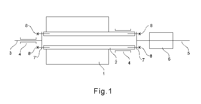
figure 1 shows a section in the axial direction of a
driving drum unit with a gearless drive;
figure 2 shows a section in the axial direction of a
reinforcement of a hollow shaft.
The references used in the drawings are summarized in
the list of references. In principle, identical parts
are provided with the same references.

CA 02830770 2013-09-19
- 5 -
WAYS TO CARRY OUT THE INVENTION
Figure 1 shows a section in the axial direction,
transversely with respect to the running direction of
the belt, of a driving drum unit of a belt drive system
and a gearless drive. A driving drum 1 rests on a drum
shaft and is mounted at both ends by drum shaft
bearings 4. The driving drum includes a hollow shaft 2
and a connecting shaft 3, which is connected to the
hollow shaft 2 by way of bolts 8 by means of a flange
7' of the connecting shaft 3 and an end face of the
hollow shaft 2 which faces the connecting shaft 3. The
connecting shaft 3 has a smaller diameter than the
outside diameter of the hollow shaft 2. A drum shaft
bearing 4 is situated in each case on the hollow shaft
2 and the connecting shaft 3. On an end of the hollow
shaft 2 which is located opposite the connecting shaft
3, a bearing-free rotor shaft 5 is connected by way of
bolts 8 by means of a flange 7 of the rotor shaft 5 and
an end face of the hollow shaft 2 which faces the rotor
shaft 5. The rotor 6 is located on the rotor shaft 5. A
stator, which is not shown in figure 1, is arranged on
the outside around the rotor 6 as a counterpart.
Figure 2 shows a section in the axial direction of a
view of a detail of a reinforcement 9 of the hollow
shaft 2. The circular ring-shaped reinforcement 9 is
fixedly connected to the hollow shaft 2 and is
positioned such that said latter together with an edge
of the hollow shaft 2 which faces the rotor shaft 5
forms an even end face in a radial plane. A face of the
flange 7 of the rotor shaft 5 which faces the hollow
shaft 2 lies on said end face and forms a contact face
for the connection between the hollow shaft 2 and the
rotor shaft 5. Bolts 8 fix the rotor shaft 5 on the
reinforcement 9.

CA 02830770 2013-09-19
- 6 -
The connecting shaft 3 does not forcibly have to be
present. It is also possible for the drum shaft only to
have one hollow shaft. In this case, it is advantageous
to use identical drum shaft bearings on both ends. As a
result, the bearing load is the same. There is no
asymmetrical deformation on the driving drum 1 and a
clean run of the conveyor belt is thus ensured. The
hollow shaft 2 does not have to be continuous. The
hollow shaft 2 could also be flanged or fastened in
another manner at the end face of the driving drum.
Instead of by means of a flange 7, the rotor shaft 5
can also be inserted directly through the rotor shaft 5
by means of stay-bolts, which are inserted into the
reinforcement 9 of the hollow shaft 2, and can be
secured on a rear side of the rotor shaft 5. In place
of bolts for fastening, it is also possible to use
other releasable connecting elements such as, for
instance, rivets. The geometry of the reinforcements 9
can be selected in an arbitrary manner. Particularly
advantageous in this case are rotationally-symmetrical
geometries as these do not produce any unbalance of the
drum shaft. Neither does the position of the
reinforcement 9 have to be forcibly directly on an end
of the hollow shaft 2. It is also possible to place the
reinforcement 9 in a region close to the flange inside
the hollow shaft 2.

CA 02830770 2013-09-19
- 7 -
LIST OF REFERENCES
1 Driving drum
2 Hollow shaft
3 Connecting shaft
4 Drum shaft bearing
Rotor shaft
6 Rotor
7,7' Flange
8 Bolt
9 Reinforcement

Representative Drawing
A single figure which represents the drawing illustrating the invention.
Administrative Status

2024-08-01:As part of the Next Generation Patents (NGP) transition, the Canadian Patents Database (CPD) now contains a more detailed Event History, which replicates the Event Log of our new back-office solution.

Please note that "Inactive:" events refers to events no longer in use in our new back-office solution.

For a clearer understanding of the status of the application/patent presented on this page, the site Disclaimer , as well as the definitions for Patent , Event History , Maintenance Fee  and Payment History  should be consulted.

Event History

Description Date
Inactive: Dead - No reply to s.30(2) Rules requisition 2016-09-08
Application Not Reinstated by Deadline 2016-09-08
Deemed Abandoned - Failure to Respond to Maintenance Fee Notice 2016-03-08
Inactive: Abandoned - No reply to s.30(2) Rules requisition 2015-09-08
Inactive: S.30(2) Rules - Examiner requisition 2015-03-05
Inactive: Report - No QC 2015-02-24
Inactive: Cover page published 2013-11-08
Inactive: Acknowledgment of national entry - RFE 2013-10-29
Application Received - PCT 2013-10-29
Inactive: First IPC assigned 2013-10-29
Inactive: IPC assigned 2013-10-29
Letter Sent 2013-10-29
Request for Examination Requirements Determined Compliant 2013-09-19
All Requirements for Examination Determined Compliant 2013-09-19
National Entry Requirements Determined Compliant 2013-09-19
Application Published (Open to Public Inspection) 2012-09-27

Abandonment History

Abandonment Date Reason Reinstatement Date
2016-03-08

Maintenance Fee

The last payment was received on 2015-02-18

Note : If the full payment has not been received on or before the date indicated, a further fee may be required which may be one of the following

  • the reinstatement fee;
  • the late payment fee; or
  • additional fee to reverse deemed expiry.

Patent fees are adjusted on the 1st of January every year. The amounts above are the current amounts if received by December 31 of the current year.
Please refer to the CIPO Patent Fees web page to see all current fee amounts.

Fee History

Fee Type Anniversary Year Due Date Paid Date
Request for examination - standard 2013-09-19
Basic national fee - standard 2013-09-19
MF (application, 2nd anniv.) - standard 02 2014-03-10 2014-02-18
MF (application, 3rd anniv.) - standard 03 2015-03-09 2015-02-18
Owners on Record

Note: Records showing the ownership history in alphabetical order.

Current Owners on Record
ABB SCHWEIZ AG
Past Owners on Record
URS MAIER
Past Owners that do not appear in the "Owners on Record" listing will appear in other documentation within the application.
Documents

To view selected files, please enter reCAPTCHA code :


To view images, click a link in the Document Description column (Temporarily unavailable). To download the documents, select one or more checkboxes in the first column and then click the "Download Selected in PDF format (Zip Archive)" or the "Download Selected as Single PDF" button.

List of published and non-published patent-specific documents on the CPD .

If you have any difficulty accessing content, you can call the Client Service Centre at 1-866-997-1936 or send them an e-mail at CIPO Client Service Centre.

({010=All Documents, 020=As Filed, 030=As Open to Public Inspection, 040=At Issuance, 050=Examination, 060=Incoming Correspondence, 070=Miscellaneous, 080=Outgoing Correspondence, 090=Payment})


Document
Description 
Date
(yyyy-mm-dd) 
Number of pages   Size of Image (KB) 
Description 2013-09-18 7 227
Claims 2013-09-18 3 105
Drawings 2013-09-18 2 11
Representative drawing 2013-09-18 1 3
Abstract 2013-09-18 1 13
Acknowledgement of Request for Examination 2013-10-28 1 189
Notice of National Entry 2013-10-28 1 231
Reminder of maintenance fee due 2013-11-11 1 111
Courtesy - Abandonment Letter (R30(2)) 2015-11-02 1 164
Courtesy - Abandonment Letter (Maintenance Fee) 2016-04-18 1 174
PCT 2013-09-18 4 149